Ford Fusion: Engine - 1.5L EcoBoost (118kW/160PS) – I4 / Engine. Installation
Special Tool(s) /
General Equipment
 |
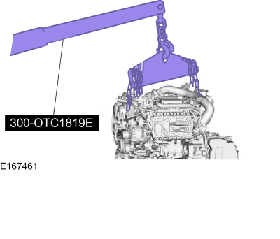
300-OTC1819E
2,200# Floor Crane, Fold Away |
 |
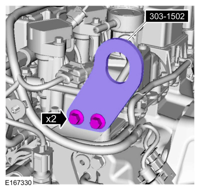
303-1502
Lifting Device Engine
TKIT-2012A-FL
TKIT-2012A-ROW |
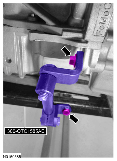
| Adjustable Mounting Arm |
| Hose Clamp Remover/Installer |
Materials
| Name |
Specification |
Motorcraft® Multi-Purpose Grease Spray
XL-5-A |
ESB-M1C93-B
|
Engine Oil - SAE 5W-20 - Synthetic Blend Motor Oil
XO-5W20-Q1SP |
WSS-M2C945-B1
|
All vehicles
-
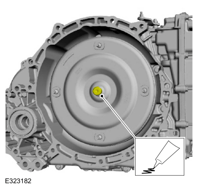
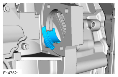
Lubricate the torque converter pilot hub with Multi-Purpose Grease.
Material: Motorcraft® Multi-Purpose Grease Spray
/ XL-5-A
(ESB-M1C93-B)
-
Inspect the engine block dowels. If the dowels are damaged or missing, install new engine block dowels.
-
Draw the engine to the transmission together and install the bolt.
Torque:
35 lb.ft (48 Nm)
-
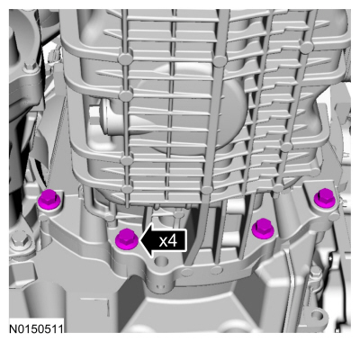
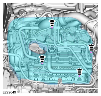
Install the engine to transmission bolts.
Torque:
35 lb.ft (48 Nm)
-
Install the engine to transmission bolts.
Torque:
35 lb.ft (48 Nm)
-
Install the Adjustable Mounting Arm.
Use the General Equipment: Adjustable Mounting Arm
-
Remove Special Service Tool: 300-OTC1819E
2,200# Floor Crane, Fold Away.
-
Remove Special Service Tool: 303-1502
Lifting Device Engine.
-
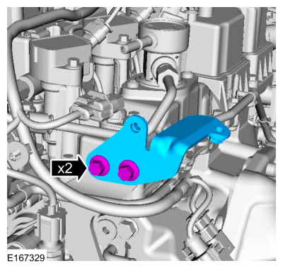
Install the bracket and the bolts.
Torque:
97 lb.in (11 Nm)
-
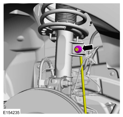
Position the halfshaft support bracket and install the bolts.
Torque:
35 lb.ft (48 Nm)
-
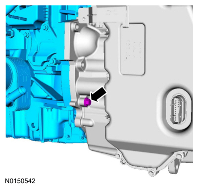
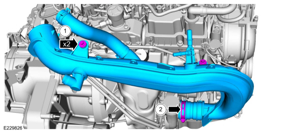
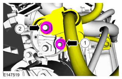
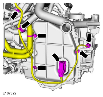
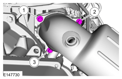
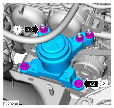
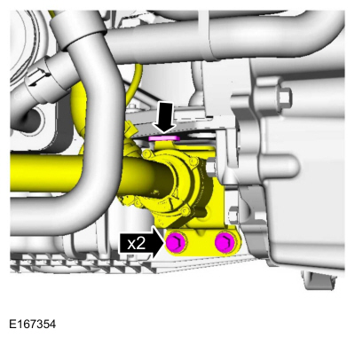
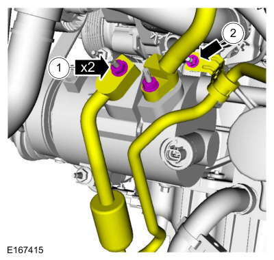
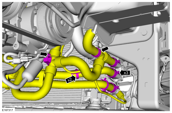
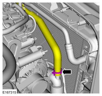
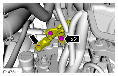
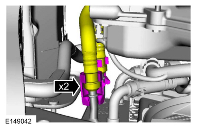
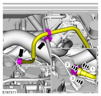
Install the TC inlet pipe, bolt and tighten the clamp.
Torque:
1:
71 lb.in (8 Nm)
2:
44 lb.in (5 Nm)
-
-
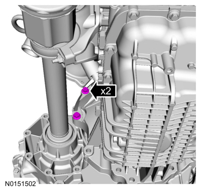
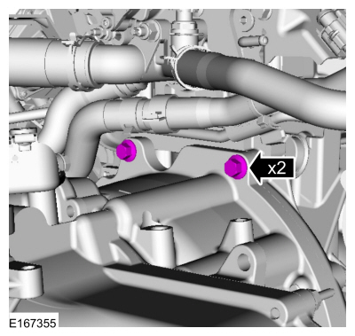
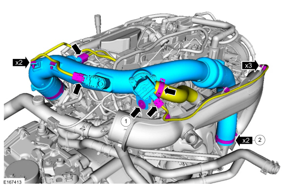
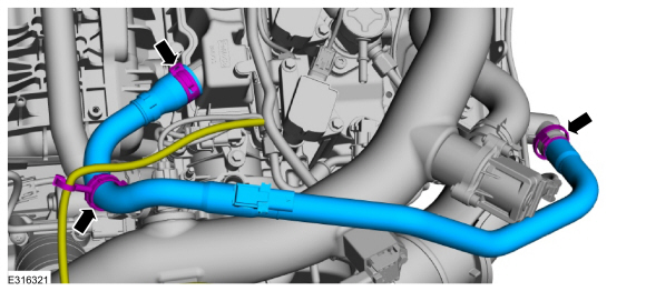
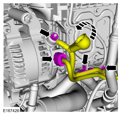
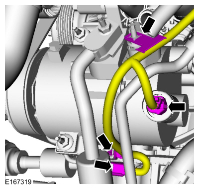
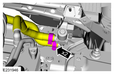
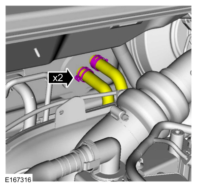
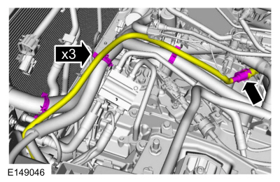
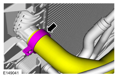
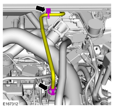
Install the TC outlet pipe, bolt and tighten the clamps.
Torque:
1:
71 lb.in (8 Nm)
2:
44 lb.in (5 Nm)
-
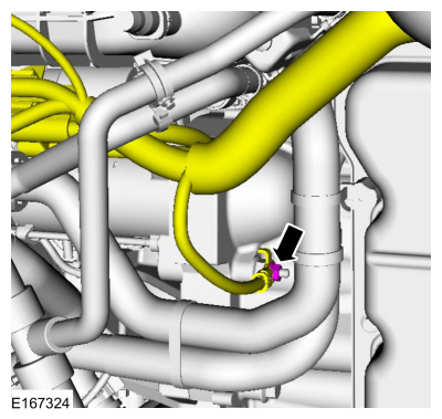
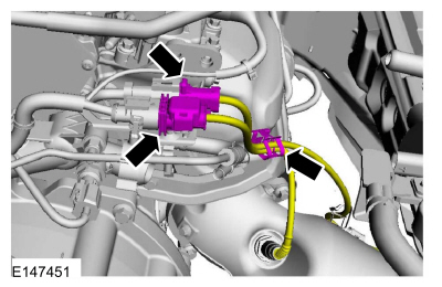
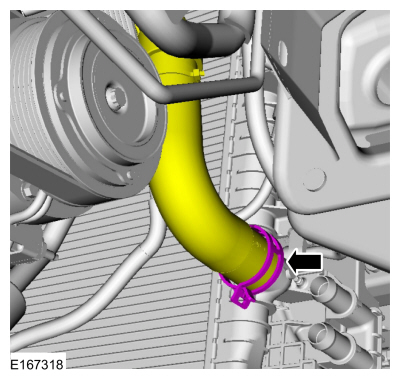
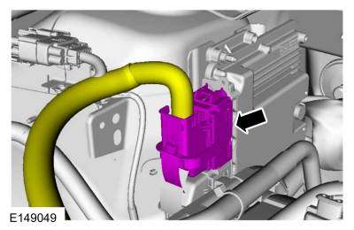
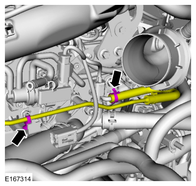
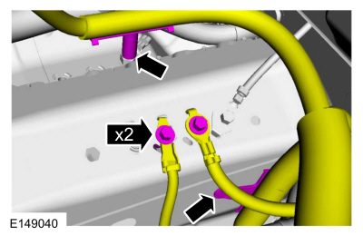
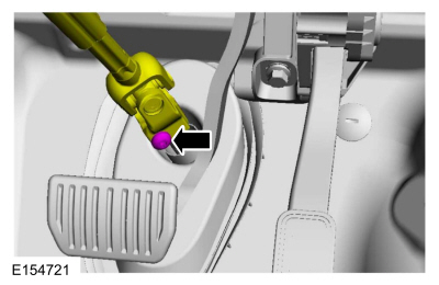
Connect the TC bypass hose.
-
Attach the wiring harness retainers and connect the electrical connectors.
-
-
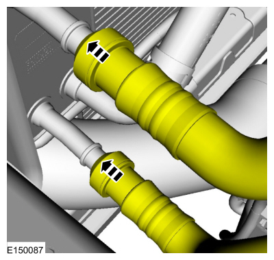
Install the crankcase vent hose.
Use the General Equipment: Hose Clamp Remover/Installer
-
Attach the wiring harness retainer.
-
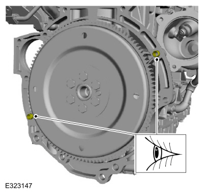
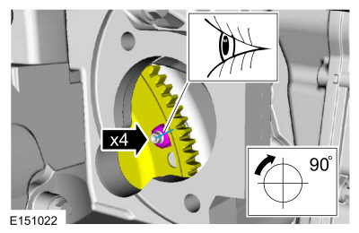
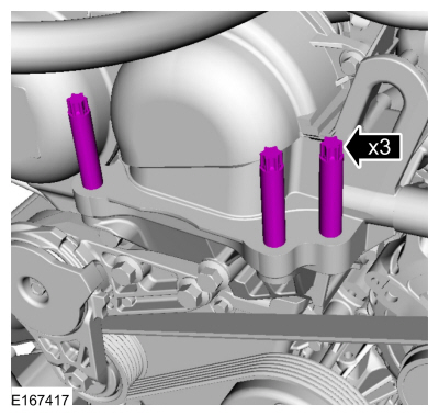
NOTE:
Only rotate the crankshaft in a clockwise direction.
Match the index-mark the torque converter nuts and tighten the nut.
Torque:
35 lb.ft (48 Nm)
-
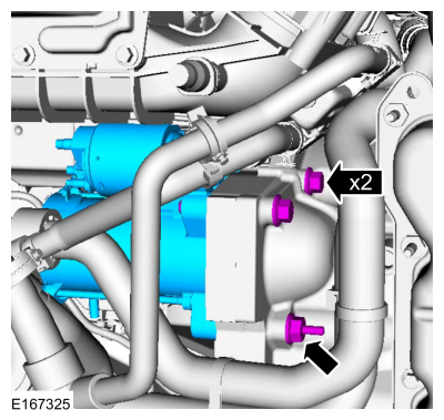
Install the starter motor insulator.
-
Install the starter motor, bolts and the stud bolt.
Torque:
35 lb.ft (48 Nm)
-
Position the wiring harness and install the nut.
Torque:
97 lb.in (11 Nm)
-
-
Position the wiring harness and install the nut.
Torque:
159 lb.in (18 Nm)
-
Slide the generator insulator down.
-
Attach the wiring harness retainers and connect the electrical connector.
-
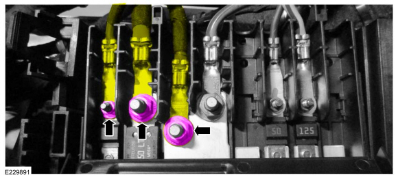
Position the starter motor cable and install the nuts.
Torque:
1:
53 lb.in (6 Nm)
2:
106 lb.in (12 Nm)
Vehicles with automatic start-stop
-
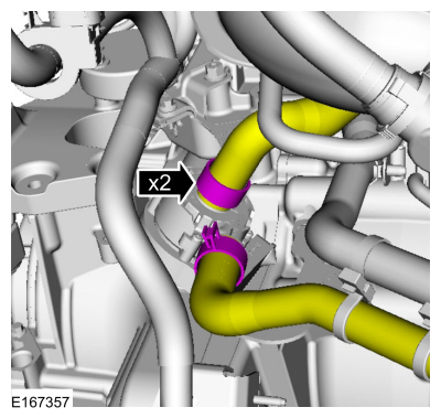
Connect the coolant hoses.
Use the General Equipment: Hose Clamp Remover/Installer
All vehicles
-
Attach the wiring harness retainers and connect the electrical connectors.
-
Install the new catalytic converter gasket and loosely install the bolts.
-
Install the catalytic converter, bolt and tighten the bolts in sequence shown.
Torque:
22 lb.ft (30 Nm)
-
Install the muffler inlet pipe isolator bracket bolts.
Torque:
18 lb.ft (25 Nm)
-
Tighten the catalytic converter mounting bolts in sequence shown.
Torque:
22 lb.ft (30 Nm)
-
NOTE:
Make sure the sensor wiring is routed away from hot
surfaces and sharp edges or damage to the wiring may occur.
Attach the retainer and connect the electrical connector.
-
Tighten the engine mount studs.
Torque:
89 lb.in (10 Nm)
-
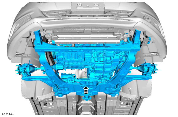
Using the powertrain lift, raise the powertrain and subframe as an assembly.
-
-
Install the engine mount and the nuts.
Torque:
85 lb.ft (115 Nm)
-
Install the engine mount bolts finger-tight.
-
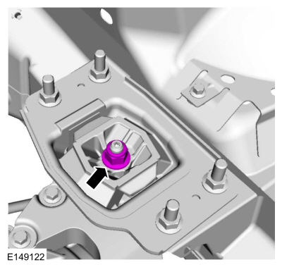
Install the transmission support insulator nut.
Torque:
98 lb.ft (133 Nm)
-
NOTE:
Align the reference marks made during removal.
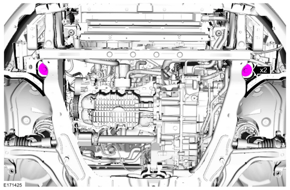
Install the subframe front mounting bolts finger-tight.
-
NOTE:
Align the reference marks made during removal.
-
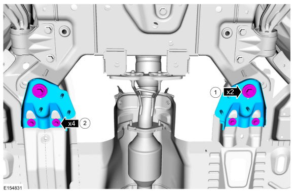
Install the subframe support bracket and the bolts finger-tight.
-
Install the subframe support bracket bolts finger-tight.
-
NOTE:
While tightening the subframe bolts, make sure the front subframe does not move.
Install the subframe rear mounting bolts.
Torque:
173 lb.ft (235 Nm)
-
-
Tighten the subframe support bracket bolts in 2 stages.
Torque:
Stage 1:
76 lb.ft (103 Nm)
Stage 2:
270°
-
Tighten the subframe support bracket bolts.
Torque:
44 lb.ft (60 Nm)
-
Remove.
Use the General Equipment: Adjustable Mounting Arm
-
Tighten the engine mount bolts.
Torque:
66 lb.ft (90 Nm)
-
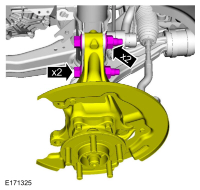
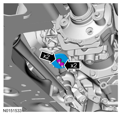
Position the RH wheel knuckle assembly, install the bolts and the nuts.
Torque:
173 lb.ft (235 Nm)
-
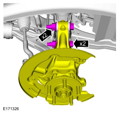
Position the LH wheel knuckle assembly, install the bolts and the nuts.
Torque:
173 lb.ft (235 Nm)
-
Install the brake disc.
Refer to: Brake Disc (206-03 Front Disc Brake, Removal and Installation).
-
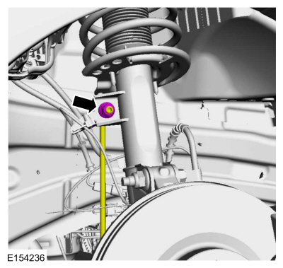
Position the RH stabilizer bar link and install the nut.
Torque:
85 lb.ft (115 Nm)
-
Position the LH stabilizer bar link and install the nut.
Torque:
85 lb.ft (115 Nm)
-
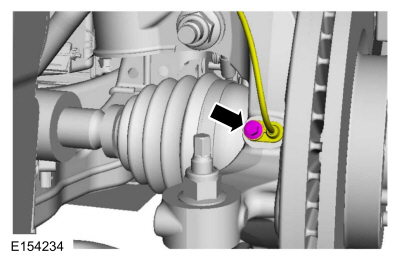
Position the wheel speed sensor and install the bolt.
Torque:
80 lb.in (9 Nm)
-
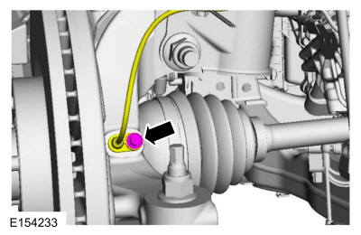
Position the wheel speed sensor and install the bolt.
Torque:
80 lb.in (9 Nm)
-
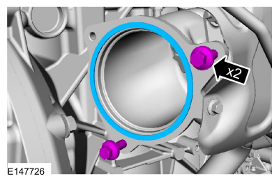
Install the catalytic converter grommet and the nuts.
Torque:
18 lb.ft (25 Nm)
-
Install the engine to transmission bolts.
Torque:
35 lb.ft (48 Nm)
-
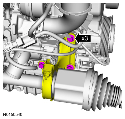
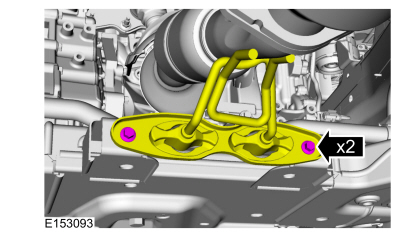
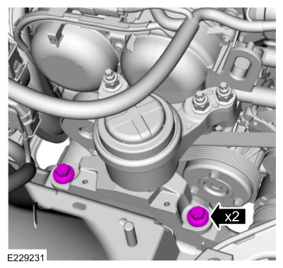
Position the auxiliary water pump and install the bolts.
Torque:
17 lb.ft (23 Nm)
-
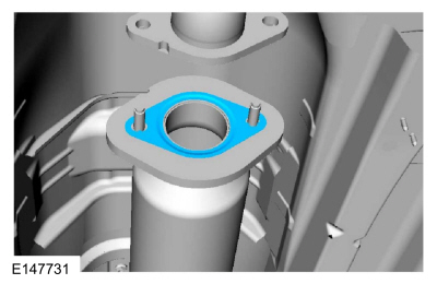
Install the new muffler inlet pipe gasket.
-
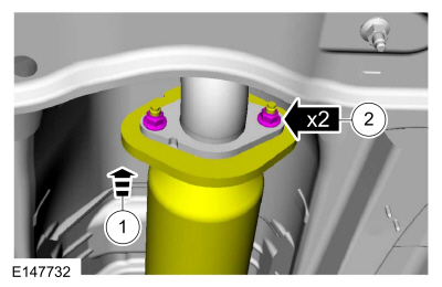
Position the muffler inlet pipe and install the nuts.
Torque:
35 lb.ft (48 Nm)
-
Install the cross support and the bolts.
Torque:
33 lb.ft (45 Nm)
-
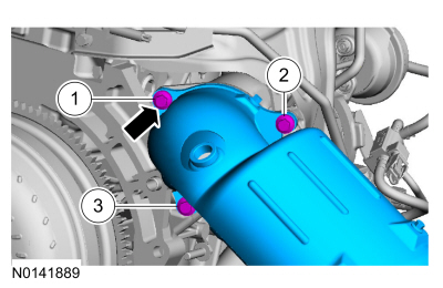
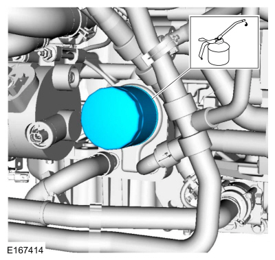
Install the engine oil filter.
Material: Engine Oil - SAE 5W-20 - Synthetic Blend Motor Oil
/ XO-5W20-Q1SP
(WSS-M2C945-B1)
Torque:
128 lb.in (14.5 Nm)
-
NOTE:
Use new O-ring seals and gasket seals.
Position the A/C lines and install the nuts.
Torque:
1:
133 lb.in (15 Nm)
2:
89 lb.in (10 Nm)
-
Connect the electrical connectors and attach the retainers.
-
Connect the coolant hose.
Use the General Equipment: Hose Clamp Remover/Installer
-
Connect the coolant hoses.
Use the General Equipment: Hose Clamp Remover/Installer
-
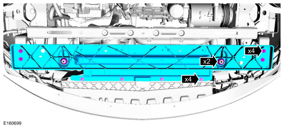
Install the lower radiator support, retainers and the bolts.
Torque:
177 lb.in (20 Nm)
-
NOTE:
LF inner fender well removed for clarity.
Connect the electrical connector.
-
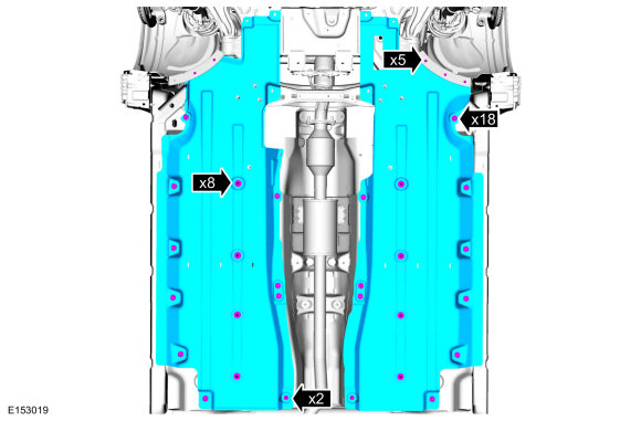
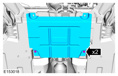
Install the deflector shields and the retainers.
-
Install the stone guard and the retainers.
-
Install the RH and LH front wheels and tires.
Refer to: Wheel and Tire (204-04A Wheels and Tires, Removal and Installation).
-
Install the accessory drive belt.
Refer to: Accessory Drive Belt (303-05A Accessory Drive - 1.5L EcoBoost (118kW/160PS) – I4, Removal and Installation).
-
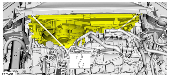
Remove the cooling module support.
-
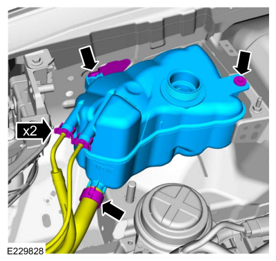
-
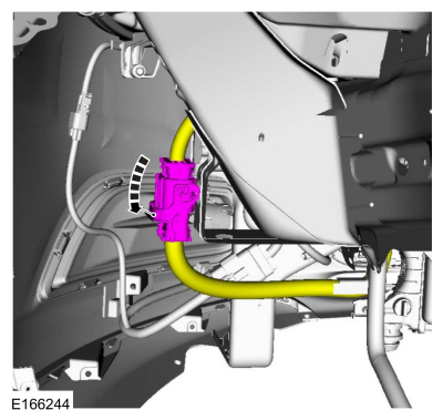
Install the degas bottle and the retainer.
Torque:
80 lb.in (9 Nm)
-
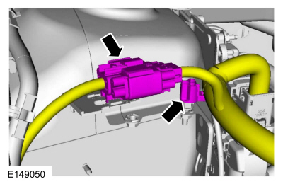
Connect the coolant hoses.
Use the General Equipment: Hose Clamp Remover/Installer
-
Attach the wiring harness retainer and connect the electrical connector.
-
Connect the PCM electrical connector.
-
Connect the coolant hose.
Use the General Equipment: Hose Clamp Remover/Installer
-
Connect the coolant hoses to the transmission fluid heater coolant control valve and install the clamps.
Use the General Equipment: Hose Clamp Remover/Installer
-
Connect the coolant hoses to the heater core.
Use the General Equipment: Hose Clamp Remover/Installer
-
Connect the gearshift cable end to selector lever assembly and install the bolts.
Torque:
18 lb.ft (25 Nm)
-
NOTE:
If equipped with block heater.
Attach the retainers and connect the coolant tube.
-
Attach the retainer and connect the coolant hose.
Use the General Equipment: Hose Clamp Remover/Installer
-
Connect the transmission fluid cooler tubes.
-
Install the transmission fluid cooler tubes secondary latches.
-
Connect the coolant hose.
Use the General Equipment: Hose Clamp Remover/Installer
-
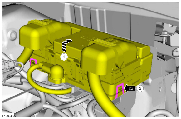
Position the wiring harness, install the bolts and attach the retainers.
Torque:
97 lb.in (11 Nm)
-
Position the wiring harness and install the nuts.
Torque:
89 lb.in (10 Nm)
-
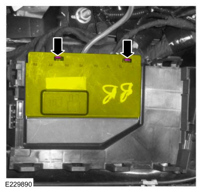
Close the battery cable terminal cover.
-
Position and install the fuse box.
-
Position the wiring harness and install the stud bolt.
Torque:
106 lb.in (12 Nm)
-
Install the EVAP canister purge valve.
Refer to: Evaporative Emission Canister Purge Valve (303-13A Evaporative Emissions - 1.5L EcoBoost (118kW/160PS) – I4, Removal and Installation).
-
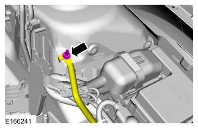
Connect the crankcase pressure sensor wiring harness electrical connector and wire harness retainer.
-
Attach the retainer and connect the vacuum tube coupling.
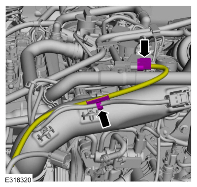
-
Attach the retainers, connect the fuel tube couplings.
-
Install the following items:
-
Install the battery tray.
Refer to: Battery Tray (414-01 Battery, Mounting and Cables, Removal and Installation).
-
Install the upper air cleaner outlet pipe.
Refer to: Air Cleaner Outlet Pipe (303-12A Intake Air Distribution and Filtering - 1.5L EcoBoost (118kW/160PS) – I4, Removal and Installation).
-
Install the air cleaner.
Refer to: Air Cleaner (303-12A Intake Air Distribution and Filtering - 1.5L EcoBoost (118kW/160PS) – I4, Removal and Installation).
-
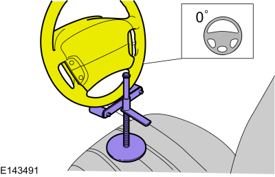
Attach the steering column shaft to steering input shaft and install the bolt.
Torque:
18 lb.ft (25 Nm)
-
Remove the special tool.
-
Fill the engine with clean engine oil.
Material: Engine Oil - SAE 5W-20 - Synthetic Blend Motor Oil
/ XO-5W20-Q1SP
(WSS-M2C945-B1)
-
Fill the cooling system.
Refer to: Engine Cooling System Draining, Vacuum Filling and Bleeding (303-03A Engine Cooling - 1.5L EcoBoost (118kW/160PS) – I4, General Procedures).
-
Adjust the selector cable.
Refer to: Selector Lever Cable Adjustment - 1.5L EcoBoost (118kW/160PS) – I4 (307-05A Automatic Transmission External Controls - 6-Speed Automatic Transmission – 6F35, General Procedures).
-
Recharge the A/C system.
Refer to: Air Conditioning (A/C) System Recovery, Evacuation and Charging - Vehicles With: R1234YF Refrigerant (412-00 Climate Control System - General Information, General Procedures).
-
Install the engine appearance cover.
-
Start and check the exhaust system for leaks.
-
Use the Powertrain Control Module (PCM) Misfire Monitor Profile Correction routine in the diagnostic scan tool.
-
Check and, if necessary, adjust front toe.
Refer to: Front Toe Adjustment (204-00 Suspension System - General Information, General Procedures).
Other information:
Depower
WARNING:
Before beginning any service procedure in this
section, refer to Safety Warnings in section 100-00 General Information.
Failure to follow this instruction may result in serious personal
injury.
NOTE:
The SRS must be fully operational and free of faults before releasing the vehicle to the customer.
Refer to: Health and Safety Precautions (100-00 Genera..
Inspection and Verification
Verify the customer concern.
Visually inspect for obvious signs of mechanical or electrical damage.
If an obvious cause for an observed or reported concern is
found, correct the cause (if possible) before proceeding to the next
step
If the cause is not visually evident, verify the symptom and refer to the Symptom Chart.
DTC Chart
..


 Engine. Assembly
