Ford Fusion: Voltage Converter/Inverter / Direct Current/Direct Current (DC/DC) Converter Control Module - System Operation and Component Description. Description and Operation
System Diagram
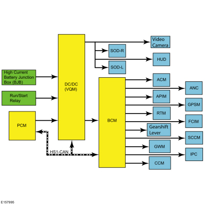
System Operation
Network Message Chart
| Broadcast Message | Originating Module | Message Purpose |
| Engine status | PCM | Used to indicate the type of cranking event occurring. If the signal is state 2, Engine Auto Stopped, then the next commanded crank is to be supported. If the signal is state 0, Engine Off, the next crank will be a key crank and the Voltage Quality Module (VQM) will not support. |
The Direct Current/Direct Current (DC/DC) converter control module also known as the Voltage Quality Module (VQM) is responsible for boosting battery voltage to specific components on vehicles with a start/stop system. When the ignition is turned on the Voltage Quality Module (VQM) initializes after receiving the Run/Start power feed from the run/start relay that is controlled by the BCM.
While in Stand-By mode the Voltage Quality Module (VQM) performs self-diagnostics and is not outputting any boost output voltage. The Voltage Quality Module (VQM) is simply passing battery voltage straight through to downstream loads when it is in Stand-By mode.
The Voltage Quality Module (VQM) continuously communicates it's status to the PCM via High Speed Controller Area Network (HS1-CAN). If the Voltage Quality Module (VQM) status is overloaded, overheated, or other faults are present the PCM will disable the start/stop system or the engine may restart if a start/stop event is already in progress. During a start/stop event the engine will shut down automatically after vehicle speed is zero. As the engine begins shutting down, there is an initial battery voltage drop due to engine shutting off and the alternator no longer providing output current.
Once the engine is no longer spinning the electrical system is fully supported by the vehicle battery. The electrical load present with the engine off phase of the Stop-start event causes a gradual decline in battery voltage. This gradual decline of battery voltage is the second voltage transition. The third voltage transition will occur during the restart of the engine, followed by the system voltage rising back to the regulation voltage point determined by the alternator output.
Just prior to the engine re-start, the Voltage Quality Module (VQM) will be commanded to stabilize/boost its output until the engine has started and system voltage regulation is established by the alternator. This command signal is sent from the PCM via hardwire circuit that is grounded by a low side driver. The Voltage Quality Module (VQM) is switched into Boost mode and the converter provides the stabilized or boost output voltage until one of the following occurs:
- Eng_D_Stat High Speed Controller Area Network (HS1-CAN) message transitions from EngAutoStopped (2) to EngOn (1)
- Boost time exceeds 5.2 seconds
- System input voltage exceeds targeted output
The Voltage Quality Module (VQM) has full bypass or stand by mode functionality within an input of 6V-16V. The Voltage Quality Module (VQM) must be able to provide the boosted voltage with a minimum 6V power net input voltage. If the supply voltage goes outside the voltage range, the Voltage Quality Module (VQM) recovers without user intervention when the supply voltage returns to the normal operating range. The Voltage Quality Module (VQM) determines the stabilized output voltage to be targeted by continuously measuring the Voltage Quality Module (VQM) input voltage. Prior to the re-start event, the Voltage Quality Module (VQM) receives the RE-CRANK signal and sets the boosted output voltage target to be equivalent to the measured input voltage. This ensures that the output voltage to the supported loads does not change.
Malfunction of the system does not lead to non-function of other vehicle systems. The system enters by-pass mode if:
- Thermal overload condition exists
- Voltage Quality Module (VQM) failure
- When detecting that the output voltage is more than 1V below input voltage and voltage boost is not available
The Voltage Quality Module (VQM) self-protects against overheating and self-recovers without user interaction after an overheating event. The VQM is internally protected from short-circuits.
Component Description
The Voltage Quality Module (VQM) is connected in series between the high current fuse box and a select number of non safety electrical loads. The majority of the loads are fused through the BCM and remaining loads are not fused and are switched on by a smart transistor located internal to the Voltage Quality Module (VQM). The smart transistor acts as a fuse and shuts off power in the event of a short to ground. The Voltage Quality Module (VQM) has a dedicated body ground and incorporates a hardwire signal circuit from the PCM which notifies the Voltage Quality Module (VQM) just prior to the engine cranking during an Autostart event.
 Direct Current/Direct Current (DC/DC) Converter Control Module - Overview. Description and Operation
OVERVIEW
The
Direct Current/Direct Current (DC/DC) converter control module also
known as the Voltage Quality Module (VQM) is used on vehicles equipped
with a start/stop system...
 Direct Current/Alternating Current (DC/AC) Inverter. Diagnosis and Testing
Inspection and Verification
Before
diagnosing or repairing the Direct Current/Alternating Current (DC/AC)
Inverter system refer to the Owner's Literature and REFER to: Direct Current/Alternating Current (DC/AC) Inverter - System Operation and Component Description (414-05 Voltage Converter/Inverter, Description and Operation)...
Other information:
Ford Fusion 2013–2020 Service Manual: Front Controls Interface Module (FCIM) - Police. Removal and Installation
Special Tool(s) / General Equipment Interior Trim Remover Removal NOTE: Removal steps in this procedure may contain installation details. NOTE: If installing a new module, it is necessary to upload the module configuration information to the scan tool prior to removing the module...
Ford Fusion 2013–2020 Service Manual: Ambient Air Temperature Sensor. Removal and Installation
Removal NOTE: Removal steps in this procedure may contain installation details. All vehicles With the vehicle in NEUTRAL, position it on a hoist. Refer to: Jacking and Lifting - Overview (100-02 Jacking and Lifting, Description and Operation)...
Categories
- Manuals Home
- 2nd Generation Ford Fusion Owners Manual
- 2nd Generation Ford Fusion Service Manual
- Transmission - 1.5L EcoBoost (118kW/160PS) – I4. Removal and Installation
- Front Controls Interface Module (FCIM). Removal and Installation
- Powertrain
- New on site
- Most important about car
Parallel Parking
The system detects available parallel parking spaces and steers your vehicle into the space. You control the accelerator, gearshift and brakes. The system visually and audibly guides you into a parallel parking space.
 Press the button once to search
for a parking space.
Press the button once to search
for a parking space.