Ford Fusion: Voltage Converter/Inverter / Direct Current/Alternating Current (DC/AC) Inverter. Diagnosis and Testing
Inspection and Verification
Before
diagnosing or repairing the Direct Current/Alternating Current (DC/AC)
Inverter system refer to the Owner's Literature and
REFER to: Direct Current/Alternating Current (DC/AC) Inverter - System Operation and Component Description (414-05 Voltage Converter/Inverter, Description and Operation).
for proper system operation.
DTC and Symptom Chart
Diagnostics in this manual assume a certain skill level and knowledge of Ford-specific diagnostic practices.
REFER to: Diagnostic Methods (100-00 General Information, Description and Operation).
Body Control Module DTC Chart
| DTC | Description | Action |
| B1330:01 | DC/AC Inverter Module: General Electrical Failure | GO to Pinpoint Test A |
| B1330:02 | DC/AC Inverter Module: General Signal Failure | GO to Pinpoint Test C |
| B1330:08 | DC/AC Inverter Module: Bus Signal / Message Failure | GO to Pinpoint Test C |
| B1330:49 | DC/AC Inverter Module: Internal Electronic Failure |
CLEAR the DTC. REPEAT the self-test. If DTC B1330:49 is retrieved again, INSTALL a new Direct Current/Alternating Current (DC/AC) Inverter. REFER to: Direct Current/Alternating Current (DC/AC) Inverter (414-05 Voltage Converter/Inverter, Removal and Installation). |
| B1330:55 | DC/AC Inverter Module: Not Configured |
CLEAR the DTC. REPEAT the self-test. If DTC B1330:55 is retrieved again, INSTALL a new Direct Current/Alternating Current (DC/AC) Inverter. REFER to: Direct Current/Alternating Current (DC/AC) Inverter (414-05 Voltage Converter/Inverter, Removal and Installation). |
| B1330:9A | DC/AC Inverter Module: Component or System Operating Conditions |
ADDRESS all other Diagnostic Trouble Codes
(DTCs) first. If no other Diagnostic Trouble Codes (DTCs) are present
ADDRESS any symptoms. REFER to SYMPTOM CHART in this section. If no
symptoms are present clear the DTC. If the C3501-9returns and no symptoms are present INSTALL a new Direct Current/Alternating Current (DC/AC) Inverter. REFER to: Direct Current/Alternating Current (DC/AC) Inverter (414-05 Voltage Converter/Inverter, Removal and Installation). |
| All Other DTCs | — |
REFER to: Body Control Module (BCM) (419-10 Multifunction Electronic Modules, Diagnosis and Testing). |
| Symptom | Possible Sources | Action |
|---|---|---|
|
|
|
|
|
|
|
|
|
|
|
|
Pinpoint Tests
Diagnostics in this manual assume a certain skill level and knowledge of Ford-specific diagnostic practices.
REFER to: Diagnostic Methods (100-00 General Information, Description and Operation).
No Power at the AC Power Point or the AC Power Point LED Indicator Flashes with the Key in the ON Position
Refer to Wiring Diagrams Cell 44 for schematic and connector information.
Normal Operation and Fault Conditions
The engine must be started for the AC outlet to begin operation. No power will be provided to the AC outlet when the LED is flashing.
REFER to: Direct Current/Alternating Current (DC/AC) Inverter - System Operation and Component Description (414-05 Voltage Converter/Inverter, Description and Operation).
NOTE: The electrical device that is powered by the AC power point must not exceed 150 watts.
NOTE: If the green LED is flashing, the AC power point may be overloaded, overheated or shorted. Unplug the electrical device from the AC power point and cycle the ignition. Refer to the Owner's Literature to determine if the electrical device is appropriate for the AC power point.
Diagnostic Trouble Code (DTC) Fault Trigger Conditions
| DTC | Description | Fault Trigger Conditions |
| B1330:01 | DC/AC Inverter Module: General Electrical Failure | Sets in the BCM when the general electrical fault is detected by the direct current/alternating current (DC/AC) inverter. |
Possible Sources
- Fuse(s)
- Direct current/alternating current (DC/AC) inverter
- AC Outlet
- Wiring, terminals or connectors
Visual Inspection and Diagnostic Pre-checks
- Verify that any device being used in the AC outlet is rated at less than 150 watts
- Verify the AC outlet is not being used with the engine off for a period longer than 13 minutes without starting the engine or cycling the ignition
- Verify the cabin temperature is less than 75ºC (167ºF)
- Verify the BCM Fuse 23 (10A) is OK.
- Verify the BJB fuse 81 (40A) is OK.
- Inspect the AC outlet for damage.
PINPOINT TEST A : NO POWER AT THE AC (ALTERNATING CURRENT) POWER POINT OR THE AC (ALTERNATING CURRENT) POWER POINT LED (LIGHT EMITTING DIODE) INDICATOR FLASHES WITH THE KEY IN THE ON POSITION
| NOTICE: Use the correct probe adapter(s) from the Flex Probe Kit when taking measurements. Failure to use the correct probe adapter(s) may damage the connector. | ||||||||||||||||||||||||||||
| A1 CHECK THE POWER OUTLET LED (LIGHT EMITTING DIODE) STATUS | ||||||||||||||||||||||||||||
Did the LED illuminate?
|
||||||||||||||||||||||||||||
| A2 DETERMINE IF THE DC/AC INVERTER IS OVERHEATED | ||||||||||||||||||||||||||||
Is the vehicle cabin temperature is greater than 75º C (167º F) or has the inverter been in continuous use for a long period of time?
|
||||||||||||||||||||||||||||
| A3 CHECK AC (ALTERNATING CURRENT) POWER OUTLET OPERATION | ||||||||||||||||||||||||||||
Is the device operating?
|
||||||||||||||||||||||||||||
| A4 CHECK THE POWER SUPPLY CIRCUITS FOR VOLTAGE | ||||||||||||||||||||||||||||
Are the voltages greater than 11 volts?
|
||||||||||||||||||||||||||||
| A5 CHECK THE GROUND CIRCUIT FOR AN OPEN | ||||||||||||||||||||||||||||
Is the resistance less than 3 ohms?
|
||||||||||||||||||||||||||||
| A6 CHECK THE AC OUTLET CIRCUITS FOR AN OPEN | ||||||||||||||||||||||||||||
Are the resistances less than 3 ohms?
|
||||||||||||||||||||||||||||
| A7 CHECK THE AC OUTLET CIRCUITS FOR A SHORT TOGETHER | ||||||||||||||||||||||||||||
Is the resistance greater than 10,000 ohms?
|
||||||||||||||||||||||||||||
| A8 CHECK THE AC OUTLET CIRCUITS FOR A SHORT TO GROUND | ||||||||||||||||||||||||||||
Are the resistances greater than 10,000 ohms?
|
||||||||||||||||||||||||||||
| A9 CHECK THE AC (ALTERNATING CURRENT) OUTLET FOR AN OPEN | ||||||||||||||||||||||||||||
Are the resistances less than 3 ohms?
|


The AC Outlet LED Indicator is Never On
Refer to Wiring Diagrams Cell 44 for schematic and connector information.
Normal Operation and Fault Conditions
The engine must be started for the AC outlet to begin operation. No power will be provided to the AC outlet when the LED is flashing.
REFER to: Direct Current/Alternating Current (DC/AC) Inverter - System Operation and Component Description (414-05 Voltage Converter/Inverter, Description and Operation).
Possible Sources
- Fuse(s)
- direct current/alternating current (DC/AC) inverter
- AC Outlet
- Wiring, terminals or connectors
Visual Inspection and Diagnostic Pre-checks
- Verify the BCM Fuse 23 (10A) is OK.
- Verify the BJB fuse 81 (40A) is OK.
- Inspect the AC outlet for damage.
PINPOINT TEST B : THE AC OUTLET LED (LIGHT EMITTING DIODE) INDICATOR IS NEVER ON
| NOTICE: Use the correct probe adapter(s) from the Flex Probe Kit when taking measurements. Failure to use the correct probe adapter(s) may damage the connector. | ||||||||||||||||||||||
| B1 CHECK THE SYSTEM OPERATION | ||||||||||||||||||||||
Is power available at the AC outlet to operate the device?
|
||||||||||||||||||||||
| B2 CHECK THE LED CONTROL CIRCUITS FOR AN OPEN | ||||||||||||||||||||||
Are the resistances less than 3 ohms?
|
||||||||||||||||||||||
| B3 CHECK THE AC OUTLET LED (LIGHT EMITTING DIODE) | ||||||||||||||||||||||
Is the resistance greater than 10,000 ohms in one direction and between 10-20 ohms in the opposite direction?
|


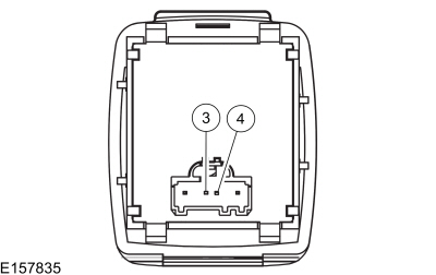 pin 4 (component side)

 pin 3 (component side)
 pin 5 (component side)

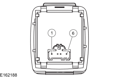 pin 6 (component side)
The AC Power Point Turns Off After 13 Minutes
Refer to Wiring Diagrams Cell 44 for schematic and connector information.
Normal Operation and Fault Conditions
The direct current/alternating current (DC/AC) inverter receives a signal from the BCM over the LIN whenever the engine is running. If the direct current/alternating current (DC/AC) inverter does not receive this message for 13 minutes, the inverter stops supplying 110 volts to the AC power outlet and the LED indicator flashes. The system can be reset by cycling the ignition from ON to OFF and back to ON, however the system only operates for another 13 minutes unless the signal is received from the BCM that the engine is running.
Diagnostic Trouble Code (DTC) Fault Trigger Conditions
| DTC | Description | Fault Trigger Conditions |
| B1330:02 | DC/AC Inverter Module: General Signal Failure | Sets in the BCM when a general signal failure occurs on the LIN. |
| B1330:08 | DC/AC Inverter Module: Bus Signal / Message Failure | Sets in the BCM when there is a LIN communication fault from the direct current/alternating current (DC/AC) inverter. |
Possible Sources
- Fuse(s)
- direct current/alternating current (DC/AC) inverter
- BCM
- Wiring, terminals or connectors
Visual Inspection and Diagnostic Pre-checks
- Verify the concern by monitoring the AC outlet LED indicator for 13 minutes with the engine running. If the LED indicator starts to flash after 13 minutes, continue to the pinpoint test. If the system continues to operate normally after 13 minutes, make sure the customer is aware of the direct current/alternating current (DC/AC) inverter time-out function.
PINPOINT TEST C : THE AC (ALTERNATING CURRENT) POWER POINT TURNS OFF AFTER 13 MINUTES
| NOTICE: Use the correct probe adapter(s) from the Flex Probe Kit when taking measurements. Failure to use the correct probe adapter(s) may damage the connector. | ||||||||||
| C1 RETRIEVE BCM (BODY CONTROL MODULE) DTCS | ||||||||||
Is DTC U0100:00, B1330:02, or B1330:08 present?
|
||||||||||
| C2 CHECK THE LIN (LOCAL INTERCONNECT NETWORK) COMMUNICATION CIRCUIT FOR A SHORT TO VOLTAGE | ||||||||||
Is any voltage present?
|
||||||||||
| C3 CHECK THE LIN (LOCAL INTERCONNECT NETWORK) COMMUNICATION CIRCUIT FOR A SHORT TO GROUND | ||||||||||
Is the resistance greater than 10,000 ohms?
|
||||||||||
| C4 CHECK THE LIN (LOCAL INTERCONNECT NETWORK) COMMUNICATION CIRCUIT FOR AN OPEN | ||||||||||
Is the resistance less than 3 ohms?
|


 Click here to access Guided Routine (BCM).
 Internet Explorer version 11 or greater is required to perform this Pinpoint Test.
 Direct Current/Direct Current (DC/DC) Converter Control Module - System Operation and Component Description. Description and Operation
System Diagram
System Operation
Network Message Chart
Broadcast Message
Originating Module
Message Purpose
Engine status
PCM
Used to indicate the type of cranking
event occurring...
 Direct Current/Direct Current (DC/DC) Converter Control Module. Diagnosis and Testing
Diagnostics in this manual assume a certain skill level and knowledge of Ford-specific diagnostic practices. REFER to: Diagnostic Methods (100-00 General Information, Description and Operation)...
Other information:
Ford Fusion 2013–2020 Owners Manual: Under Hood Overview - 1.5L EcoBoost™, 2.0L EcoBoost™, 2.5L, 2.7L EcoBoost™
Under Hood Overview - 1.5L EcoBoost™ Engine coolant reservoir. See Engine Coolant Check. Engine oil filler cap. See Engine Oil Check. Engine oil dipstick. See Engine Oil Dipstick. Brake fluid reservoir. See Brake Fluid Check. Battery. See Changing the 12V Battery...
Ford Fusion 2013–2020 Service Manual: Transmission Range Control Module (TRCM). Removal and Installation
Removal With the vehicle in N, position it on a hoist. Refer to: Jacking and Lifting - Overview (100-02 Jacking and Lifting, Description and Operation). NOTE: When installing a new TRCM, it is necessary to initiate "Default to Park"...
Categories
- Manuals Home
- 2nd Generation Ford Fusion Owners Manual
- 2nd Generation Ford Fusion Service Manual
- Transmission - 1.5L EcoBoost (118kW/160PS) – I4. Removal and Installation
- Engine - 1.5L EcoBoost (118kW/160PS) – I4
- Intake Manifold. Removal and Installation
- New on site
- Most important about car
Child Safety Locks
When these locks are set, the rear doors cannot be opened from the inside.
