Ford Fusion: Front End Sheet Metal Repairs / Dash Panel Reinforcement. Removal and Installation
Special Tool(s) / General Equipment
| 8 mm Drill Bit | |
| MIG/MAG Welding Equipment | |
| Spot Weld Drill Bit | |
| Locking Pliers |
Removal
NOTICE: Battery electric vehicle (BEV), hybrid electric vehicle (HEV) and plug-in hybrid electric vehicle (PHEV) contain a high-voltage battery. Before cutting or welding near the high-voltage battery it must be removed to avoid damage.
NOTE: Engine removed for clarity.
NOTE: Factory welds may be substituted with resistance or metal inert gas (MIG) plug welds. Resistance welds may not be placed directly over original location. They must be placed adjacent to original location and match factory welds in quantity. Metal inert gas (MIG) plug welds must equal factory welds in both location and quantity.
NOTE: Adequately protect all adjacent areas against cutting, grinding and welding procedures.
-
Remove the steering column.
Refer to: Steering Column (211-04) .
-
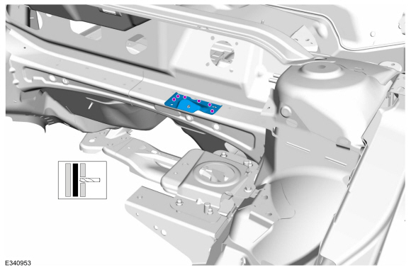
Remove the welds and the dash panel reinforcement.
Use the General Equipment: Spot Weld Drill Bit
 |
Installation
NOTICE: Battery electric vehicle (BEV), hybrid electric vehicle (HEV) and plug-in hybrid electric vehicle (PHEV) contain a high-voltage battery. Before cutting or welding near the high-voltage battery it must be removed to avoid damage.
NOTICE: The high-voltage battery in a battery electric vehicle (BEV), hybrid electric vehicle (HEV) or plug-in hybrid electric vehicle (PHEV) can be affected and damaged by excessively high temperatures. The temperature in some body shop paint booths can exceed 60° C (140° F). Therefore, during refinishing operations, the paint booth temperature must set at or below 60° C (140° F) with a bake time of 45 minutes or less. Temperatures in excess of 60° C (140° F) or bake durations longer than 45 minutes will require the high-voltage battery be removed from the vehicle prior to placing in the paint booth.
NOTICE: If refinishing cure temperatures exceed 60° C (140° F), the charge port light ring on plug-in vehicles must be removed.
NOTE: Engine removed for clarity.
NOTE: Factory welds may be substituted with resistance or metal inert gas (MIG) plug welds. Resistance welds may not be placed directly over original location. They must be placed adjacent to original location and match factory welds in quantity. Metal inert gas (MIG) plug welds must equal factory welds in both location and quantity.
NOTE: Adequately protect all adjacent areas against cutting, grinding and welding procedures.
-
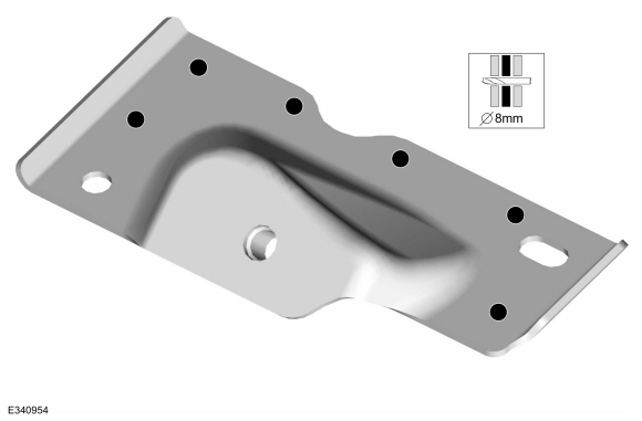
Drill plug weld holes in the replacement reinforcement.
Use the General Equipment: 8 mm Drill Bit
 |
-
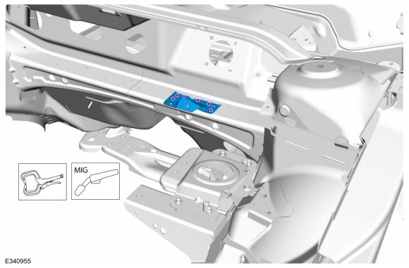
Install, properly position, clamp and weld the replacement reinforcement.
Use the General Equipment: Locking Pliers
Use the General Equipment: MIG/MAG Welding Equipment
 |
-
Dress all welds as required using typical metal finishing techniques.
-
Refinish the entire repair using a Ford approved paint system.
-
If Required:
Restore corrosion protection.
Refer to: Corrosion Prevention (501-25 Body Repairs - General Information, General Procedures).
-
Install the steering column.
Refer to: Steering Column (211-04) .

 Front Side Member Section. Removal and Installation
Special Tool(s) /
General Equipment
Resistance Spotwelding Equipment
Air Body Saw
8 mm Drill Bit
MIG/MAG Welding Equipment
Spot Weld Drill Bit
Locking Pliers
Materials
Name
Specification
Seam SealerTA-2-B, 3M™ 08308, LORD Fusor® 803DTM
-
Removal
NOTE:
The required partial replacement sections need to be cut out
from the outer side me..
Other information:
Ford Fusion 2013–2020 Service Manual: Rocker Panel Inner Reinforcement. Removal and Installation
Special Tool(s) / General Equipment Resistance Spotwelding Equipment Hot Air Gun Spot Weld Drill Bit Locking Pliers Materials Name Specification Metal Bonding AdhesiveTA-1, TA-1-B, 3M™ 08115, LORD Fusor® 108B - Seam SealerTA-2-B, 3M™ 08308, LORD Fusor® 803DTM - Removal WARNING: Before beginning any service procedu..
Ford Fusion 2013–2020 Service Manual: Brake and Clutch Systems Health and Safety Precautions. Description and Operation
WARNING: Do not use any fluid other than clean brake fluid meeting manufacturer's specification. Additionally, do not use brake fluid that has been previously drained. Following these instructions will help prevent system contamination, brake component damage and the risk of serious personal injury. WARNING: Do not breathe dust or use compressed air to blow dust from ..
Categories
- Manuals Home
- 2nd Generation Ford Fusion Owners Manual
- 2nd Generation Ford Fusion Service Manual
- Traction Control
- Cylinder Head. Removal and Installation
- Front Controls Interface Module (FCIM). Removal and Installation
- New on site
- Most important about car
Direction Indicators. Interior Lamps
Direction Indicators

Push the lever up or down to use the direction indicators.