Ford Fusion: Front End Sheet Metal Repairs / Front Side Member Section. Removal and Installation
Special Tool(s) / General Equipment
| Resistance Spotwelding Equipment | |
| Air Body Saw | |
| 8 mm Drill Bit | |
| MIG/MAG Welding Equipment | |
| Spot Weld Drill Bit | |
| Locking Pliers |
Materials
| Name | Specification |
|---|---|
| Seam Sealer TA-2-B, 3M™ 08308, LORD Fusor® 803DTM |
- |
Removal
NOTE: The required partial replacement sections need to be cut out from the outer side member with apron panel or from the inner side member.
-
Follow the health and safety precautions. WARNING:
Before beginning any service procedure in this
section, refer to Safety Warnings in section 100-00 General Information.
Failure to follow this instruction may result in serious personal
injury.
WARNING:
Before beginning any service procedure in this
section, refer to Safety Warnings in section 100-00 General Information.
Failure to follow this instruction may result in serious personal
injury.
Refer to: Health and Safety Precautions (100-00 General Information, Description and Operation).
-
Remove the following items.
Refer to: Fender Apron Panel Reinforcement (501-27 Front End Sheet Metal Repairs, Removal and Installation).
Refer to: Front Bumper (501-19 Bumpers, Removal and Installation).
Refer to: Engine (303-01C Engine - 2.5L Duratec (125kW/170PS), Removal).
Refer to: Radiator (303-03B Engine Cooling - 2.0L EcoBoost (184kW/250PS) – MI4, Removal and Installation).
Refer to: Radiator (303-03C Engine Cooling - 2.5L Duratec (125kW/170PS), Removal and Installation).
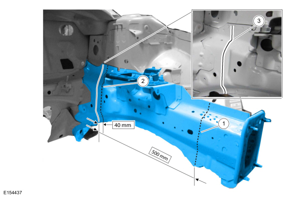
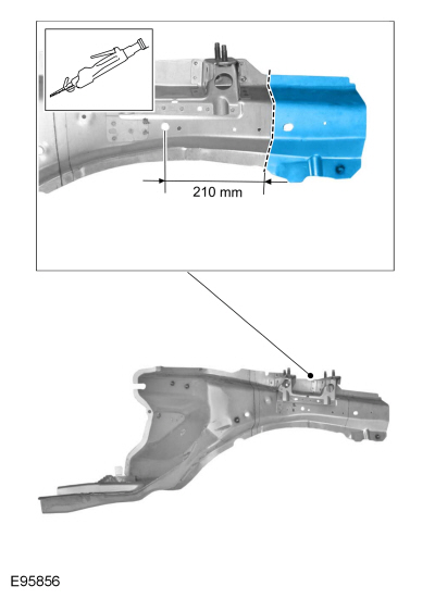
NOTICE: Due to the positions of inner reinforcements and laser weld seams it is important to follow indicated dimensions of cut points.
-
NOTE: Sectioning cut locations apply to right hand (RH) and left hand (LH) side.
NOTE: Overview of possible sectioning locations. Do not cut within 40 mm of laser welded seam.
-
Long section measurement.
-
Short section measurement.
-
Laser welded seam.
-
Long section measurement.
 |
-
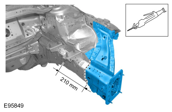
Carefully cut the front side member frame rail.
Use the General Equipment: Air Body Saw
 |
-
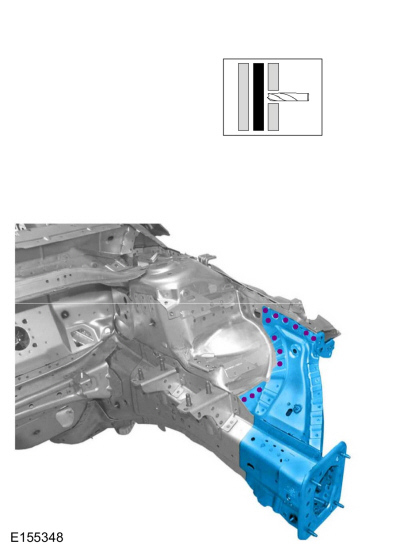
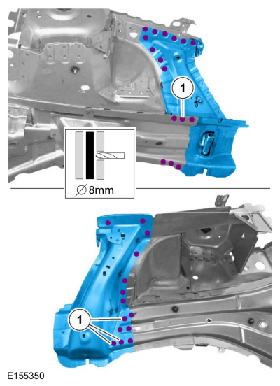
Drill out the spot welds.
Use the General Equipment: Spot Weld Drill Bit
 |
-
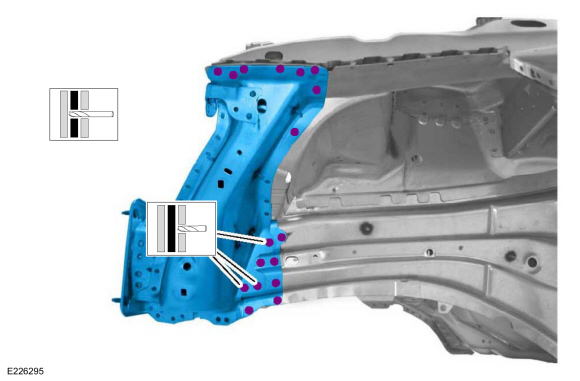
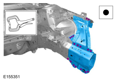
Drill out the spot welds and remove the front side member section.
Use the General Equipment: Spot Weld Drill Bit
 |
Installation
 WARNING:
Before beginning any service procedure in this section,
refer to Safety Warnings in section 100-00 General Information. Failure
to follow this instruction may result in serious personal injury.
WARNING:
Before beginning any service procedure in this section,
refer to Safety Warnings in section 100-00 General Information. Failure
to follow this instruction may result in serious personal injury.
NOTE: The required partial replacement section needs to cut out from the service replacement part.
-
Cut replacement assembly to fit repair.
Use the General Equipment: Air Body Saw
 |
-
NOTE: Indicated holes will be used for puddle welding.
-
Install the spot welds.
Use the General Equipment: 8 mm Drill Bit
-
Install the spot welds.
 |
-
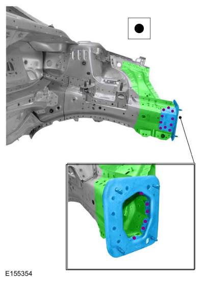
Install and properly position the component and install spot welds.
Use the General Equipment: Resistance Spotwelding Equipment
Use the General Equipment: Locking Pliers
 |
-
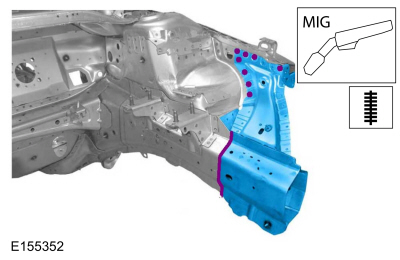
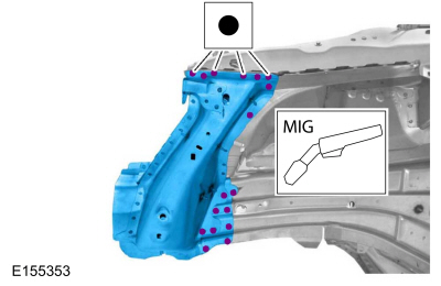
Seam weld as indicated.
Use the General Equipment: MIG/MAG Welding Equipment
 |
-
Install spot welds.
Use the General Equipment: Resistance Spotwelding Equipment
Use the General Equipment: MIG/MAG Welding Equipment
 |
-
Install the bumper bracket and spot weld.
Use the General Equipment: Resistance Spotwelding Equipment
 |
-
Finish the repair area using typical metal finishing procedures.
-
Sealing work: All areas must be sealed to production level.
Material: Seam Sealer / TA-2-B, 3M™ 08308, LORD Fusor® 803DTM
-
Refinish using a Ford approved paint system.
-
Restore corrosion protection.
Refer to: Corrosion Prevention (501-25 Body Repairs - General Information, General Procedures).
-
Install the following items.
Refer to: Fender Apron Panel Reinforcement (501-27 Front End Sheet Metal Repairs, Removal and Installation).
Refer to: Front Bumper (501-19 Bumpers, Removal and Installation).
Refer to: Engine (303-01C Engine - 2.5L Duratec (125kW/170PS), Installation).
Refer to: Radiator (303-03B Engine Cooling - 2.0L EcoBoost (184kW/250PS) – MI4, Removal and Installation).
Refer to: Radiator (303-03C Engine Cooling - 2.5L Duratec (125kW/170PS), Removal and Installation).
 Dash Panel Reinforcement. Removal and Installation
Special Tool(s) /
General Equipment
8 mm Drill Bit
MIG/MAG Welding Equipment
Spot Weld Drill Bit
Locking Pliers
Removal
NOTICE:
Battery electric vehicle (BEV), hybrid electric vehicle
(HEV) and plug-in hybrid electric vehicle (PHEV) contain a high-voltage
battery...
 Fender Apron Panel Reinforcement. Removal and Installation
Special Tool(s) /
General Equipment
Resistance Spotwelding Equipment
Spherical Cutter
Grinder
8 mm Drill Bit
MIG/MAG Welding Equipment
Spot Weld Drill Bit
Locking Pliers
Materials
Name
Specification
Seam SealerTA-2-B, 3M™ 08308, LORD Fusor® 803DTM
-
Removal
WARNING:
Before beginning any service procedure in this
se..
Other information:
Ford Fusion 2013–2020 Service Manual: Turbocharger - Overview. Description and Operation
Overview NOTICE: Whenever turbocharger air intake system components are removed, always cover open ports to protect from debris. It is important that no foreign material enter the system. The turbocharger compressor vanes are susceptible to damage from even small particles. All components should be inspected and cleaned, if necessary, prior to installation or reassembly. The turbochar..
Ford Fusion 2013–2020 Service Manual: B-Pillar Outer Panel. Removal and Installation
Special Tool(s) / General Equipment Resistance Spotwelding Equipment Spherical Cutter Hot Air Gun 8 mm Drill Bit MIG/MAG Welding Equipment Spot Weld Drill Bit Locking Pliers Materials Name Specification Metal Bonding AdhesiveTA-1, TA-1-B, 3M™ 08115, LORD Fusor® 108B - Seam SealerTA-2-B, 3M™ 08308, LORD Fusor® 803DTM - ..
Categories
- Manuals Home
- 2nd Generation Ford Fusion Owners Manual
- 2nd Generation Ford Fusion Service Manual
- Powertrain
- Front Controls Interface Module (FCIM). Removal and Installation
- Cylinder Head. Removal and Installation
- New on site
- Most important about car
Understanding Your Tire Pressure Monitoring System
The tire pressure monitoring system measures pressure in your road tires and sends the tire pressure readings to your vehicle. You can view the tire pressure readings through the information display. The low tire pressure warning light will turn on if the tire pressure is significantly low. Once the light is illuminated, your tires are under-inflated and need to be inflated to the manufacturer’s recommended tire pressure. Even if the light turns on and a short time later turns off, your tire pressure still needs to be checked.