Ford Fusion: Interior Trim and Ornamentation / C-Pillar Upper Trim Panel. Removal and Installation
Ford Fusion 2013–2020 Service Manual / Body and Paint / Body and Paint / Interior Trim and Ornamentation / C-Pillar Upper Trim Panel. Removal and Installation
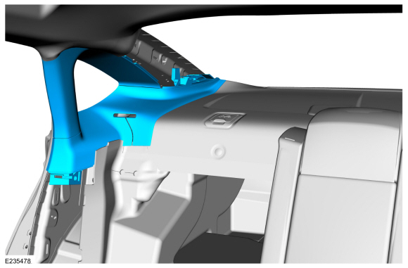
Removal
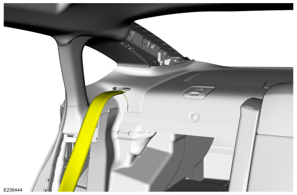
NOTE: RH side shown, LH side similar.
NOTE: Removal steps in this procedure may contain installation details.
-
Remove the C-pillar lower trim panel.
Refer to: C-Pillar Lower Trim Panel (501-05 Interior Trim and Ornamentation, Removal and Installation).
-
Remove the D-pillar trim panel.
Refer to: D-Pillar Trim Panel (501-05 Interior Trim and Ornamentation, Removal and Installation).
-
Position the rear seatbelt aside.
 |
-
-
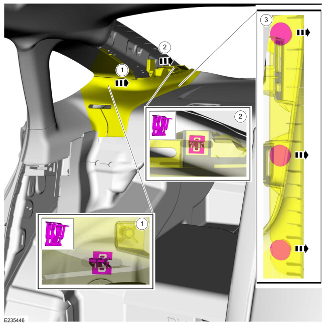
Release the front clip.
-
Release the rear clip.
-
Slide the C-pillar upper trim panel to the side,
releasing it from the heads of parcel shelf pin-type retainers.
-
Release the front clip.
 |
-
Release the front clip, pin-type retainer and four way locator pin.
 |
-
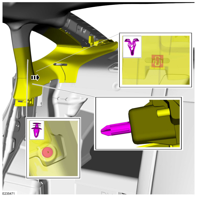
NOTICE: The trim panel must be positioned rearward to allow the upper clip to release correctly. Failure to follow this may cause damage to the trim panel.
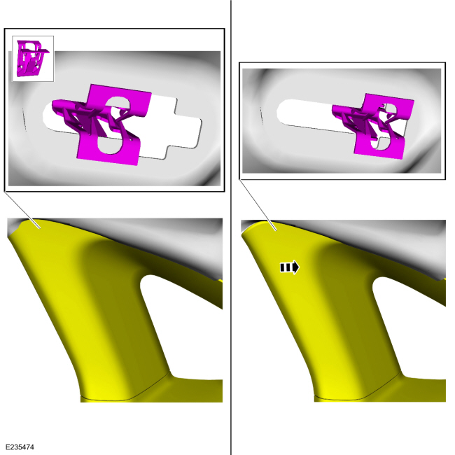
Slide the upper C-pillar trim panel rearward, aligning the clip to the slot in the sheet metal.
 |
-
Remove the upper C-pillar trim panel.
 |
Installation
NOTE: During installation, make sure the seatbelt webbing is not twisted and the seatbelts and buckles are accessible to the occupants.
-
To install, reverse the removal procedure.
-
Check the seatbelt system for correct operation.
Refer to: Seatbelt Systems (501-20A Seatbelt Systems, Diagnosis and Testing).
 B-Pillar Trim Panel. Removal and Installation
Removal
NOTE:
RH side shown, LH side similar.
NOTE:
Removal steps in this procedure may contain installation details.
Position the front seat in the full forward position...
 C-Pillar Lower Trim Panel. Removal and Installation
Removal
NOTE:
RH side shown, LH side similar.
WARNING:
Before beginning any service procedure in this
section, refer to Safety Warnings in section 100-00 General Information...
Other information:
Ford Fusion 2013–2020 Service Manual: Brake Disc Shield. Removal and Installation
Removal NOTE: Removal steps in this procedure may contain installation details. Remove the brake disc. Refer to: Brake Disc (206-03 Front Disc Brake, Removal and Installation). Remove the bolts and brake disc shield. Torque: 106 lb...
Ford Fusion 2013–2020 Service Manual: Wheel Knuckle. Removal and Installation
Special Tool(s) / General Equipment Tie Rod End Remover Removal NOTICE: Suspension fasteners are critical parts that affect the performance of vital components and systems. Failure of these fasteners may result in major service expense...
Categories
- Manuals Home
- 2nd Generation Ford Fusion Owners Manual
- 2nd Generation Ford Fusion Service Manual
- Automatic Transmission - 6-Speed Automatic Transmission – 6F35
- Powertrain
- Garage Door Opener
- New on site
- Most important about car
Parallel Parking
The system detects available parallel parking spaces and steers your vehicle into the space. You control the accelerator, gearshift and brakes. The system visually and audibly guides you into a parallel parking space.
 Press the button once to search
for a parking space.
Press the button once to search
for a parking space.
Copyright © 2026 www.fofusion2.com