
Ford Fusion: Interior Trim and Ornamentation / B-Pillar Trim Panel. Removal and Installation
Ford Fusion 2013–2020 Service Manual / Body and Paint / Body and Paint / Interior Trim and Ornamentation / B-Pillar Trim Panel. Removal and Installation
Removal
NOTE: RH side shown, LH side similar.
NOTE: Removal steps in this procedure may contain installation details.
-
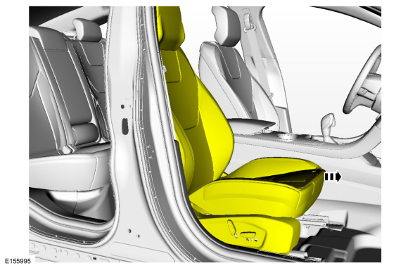
Position the front seat in the full forward position.
 |
-
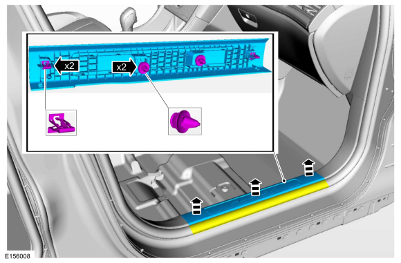
Position the front door weatherstrip aside, release the
clips and remove the front door scuff plate trim panel.
 |
-
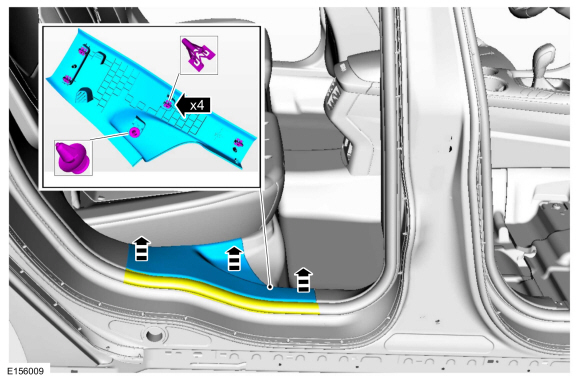
Position aside the rear door weatherstrip, release the clips and remove the rear door scuff plate trim panel.
 |
-
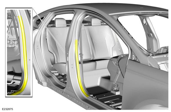
Position aside the front door and the rear door weatherstrip.
 |
-
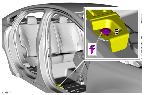
Release the pin-type retainer and position the front corner of the lower B-pillar trim panel up.
 |
-
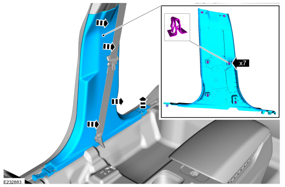
Release the clips and remove the lower B-pillar trim panel.
 |
-
Remove the seatbelt D-ring bolt.
-
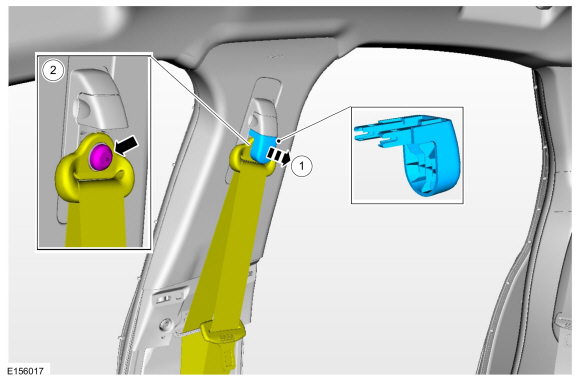
Pull straight off to release the retainers and remove the D-ring bolt cover.
-
Remove the D-ring bolt and position aside the seatbelt.
Torque: 30 lb.ft (40 Nm)
-
Pull straight off to release the retainers and remove the D-ring bolt cover.
 |
-
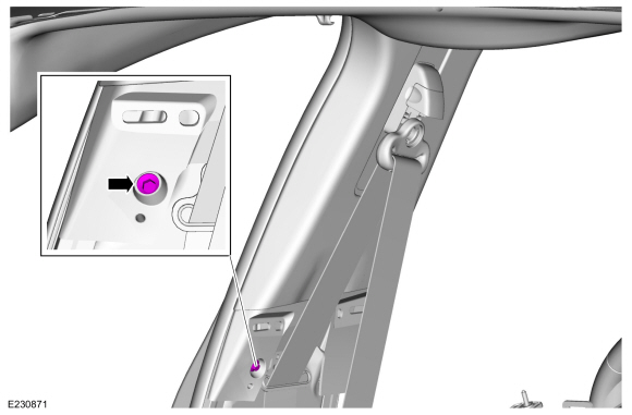
Remove the upper B-pillar trim panel bolt.
Torque: 80 lb.in (9 Nm)
 |
-
Release the upper B-pillar trim panel lower clip.
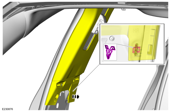 |
-
NOTICE: The trim panel must be positioned downward to allow the upper clips to release correctly. Failure to follow this may cause damage to the trim panel.
Slide the upper B-pillar down, aligning the clips to the slots in the sheet metal.
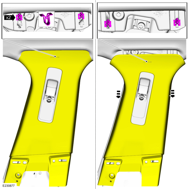 |
-
Remove the upper B-pillar trim panel.
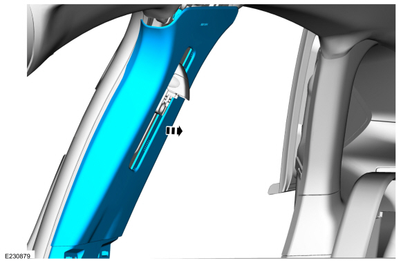 |
Installation
-
NOTE: During installation, make sure the seatbelt webbing is not twisted and the seatbelts and buckles are accessible to the occupants.
To install, reverse the removal procedure.
 A-Pillar Trim Panel. Removal and Installation
Removal
NOTE:
RH side shown, LH side similar.
Release the retainers and remove the instrument panel side trim panel.
Position aside the front door weatherstrip...
 C-Pillar Upper Trim Panel. Removal and Installation
Removal
NOTE:
RH side shown, LH side similar.
NOTE:
Removal steps in this procedure may contain installation details.
Remove the C-pillar lower trim panel...
Other information:
Ford Fusion 2013–2020 Service Manual: Wheel Studs. Removal and Installation
Special Tool(s) / General Equipment Hydraulic Press Removal Remove the front wheel bearing and wheel hub. Refer to: Front Wheel Bearing and Wheel Hub (204-01 Front Suspension, Removal and Installation). Press the wheel stud from the wheel bearing and wheel hub...
Ford Fusion 2013–2020 Owners Manual: In California (U.S. Only)
California Civil Code Section 1793.2(d) requires that, if a manufacturer or its representative is unable to repair a motor vehicle to conform to the vehicle’s applicable express warranty after a reasonable number of attempts, the manufacturer shall be required to either replace the vehicle with one substantially identical or repurchase the vehicle and reimburse the buyer in an amount eq..
Categories
- Manuals Home
- 2nd Generation Ford Fusion Owners Manual
- 2nd Generation Ford Fusion Service Manual
- Body Control Module (BCM). Removal and Installation
- Memory Function
- Electronic Parking Brake (EPB) Service Mode Activation and Deactivation. General Procedures
- New on site
- Most important about car
Cross Traffic Alert System Sensors
The sensors are behind the rear bumper on both sides of your vehicle.

Copyright © 2026 www.fofusion2.com