Ford Fusion: Fuel Tank and Lines - 1.5L EcoBoost (118kW/160PS) – I4 / Fuel Tank Filler Pipe. Removal and Installation
Ford Fusion 2013–2020 Service Manual / Powertrain / Fuel System - General Information / Fuel Tank and Lines - 1.5L EcoBoost (118kW/160PS) – I4 / Fuel Tank Filler Pipe. Removal and Installation
Removal
NOTE: Removal steps in this procedure may contain installation steps.
-
Refer to: Gasoline and Gasoline-Ethanol Fuel Systems Health and Safety Precautions (100-00 General Information, Description and Operation). WARNING:
Before beginning any service procedure in this
section, refer to Safety Warnings in section 100-00 General Information.
Failure to follow this instruction may result in serious personal
injury.
WARNING:
Before beginning any service procedure in this
section, refer to Safety Warnings in section 100-00 General Information.
Failure to follow this instruction may result in serious personal
injury.
-
With the vehicle in NEUTRAL, position it on a hoist.
Refer to: Jacking and Lifting - Overview (100-02 Jacking and Lifting, Description and Operation).
-
Disconnect the battery ground cable.
Refer to: Battery Disconnect and Connect (414-01 Battery, Mounting and Cables, General Procedures).
-
Drain the fuel tank.
Refer to: Fuel Tank Draining (310-00A Fuel System - General Information - 1.5L EcoBoost (118kW/160PS) – I4, General Procedures).
-
Remove the rear wheel on the left-hand side.
Refer to: Wheel and Tire (204-04A Wheels and Tires, Removal and Installation).
-
Remove the nuts.
 |
-
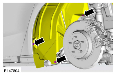
Remove the pushpins and position aside rear wheel splash shield aside.
 |
-
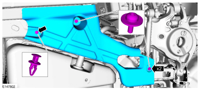
Remove the screws, the clip and the air deflector.
 |
-
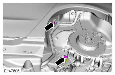
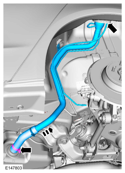
Disconnect the vapor tube Quick Release Coupling and remove the bolt.
Torque: 80 lb.in (9 Nm)
 |
-
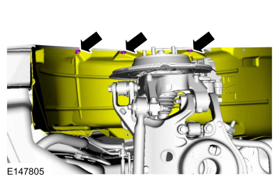
Release the clamp and disconnect the fuel tank filler pipe from the fuel tank.
Torque: 36 lb.in (4.1 Nm)
 |
Installation
-
To install, reverse the removal procedure.
 Fuel Tank. Removal and Installation
Special Tool(s) /
General Equipment
Hose Clamp(s)
Powertrain Jack
Removal
NOTE:
Removal steps in this procedure may contain installation steps...
 Fuel Level Sender. Removal and Installation
Removal
NOTE:
Removal steps in this procedure may contain installation details.
WARNING:
Before beginning any service procedure in this
section, refer to Safety Warnings in section 100-00 General Information...
Other information:
Ford Fusion 2013–2020 Owners Manual: Windshield Washers
Pull the lever toward you to operate the windshield washers. When you release the lever, the wipers operate for a short time. When activated, a courtesy wipe occurs a short time after the wipers stop to clear any remaining washer fluid. Note: You can switch courtesy wipe on or off in the information display...
Ford Fusion 2013–2020 Service Manual: Luggage Compartment Lid Alignment. General Procedures
Check Check the body to luggage compartment lid dimensions. Refer to: Body and Frame (501-26 Body Repairs - Vehicle Specific Information and Tolerance Checks, Description and Operation). Adjustment Remove the luggage compartment lid latch...
Categories
- Manuals Home
- 2nd Generation Ford Fusion Owners Manual
- 2nd Generation Ford Fusion Service Manual
- Intake Manifold. Removal and Installation
- Garage Door Opener
- Main Control Valve Body. Removal and Installation
- New on site
- Most important about car
Adjusting the Steering Wheel
WARNING: Do not adjust the steering wheel when your vehicle is moving.
Note: Make sure that you are sitting in the correct position.
Copyright © 2026 www.fofusion2.com