Ford Fusion: Intake Air Distribution and Filtering - 1.5L EcoBoost (118kW/160PS) – I4 / Air Cleaner Outlet Pipe. Removal and Installation
Ford Fusion 2013–2020 Service Manual / Powertrain / Engine / Intake Air Distribution and Filtering - 1.5L EcoBoost (118kW/160PS) – I4 / Air Cleaner Outlet Pipe. Removal and Installation
Special Tool(s) / General Equipment
| Hose Clamp Remover/Installer |
Removal
NOTICE: The turbocharger compressor vanes can be damaged by even the smallest particles. When removing any turbocharger or engine air intake system component, ensure that no debris enters the system. Failure to do so may result in damage to the turbocharger.
NOTE: Removal steps in this procedure may contain installation details.
Upper air cleaner outlet pipe
-
Release the clamp and position the tube aside.
Use the General Equipment: Hose Clamp Remover/Installer
 |
-
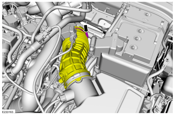
Loosen the clamps and remove the upper air cleaner outlet pipe.
Torque: 44 lb.in (5 Nm)
 |
Lower air cleaner outlet pipe
-
With the vehicle in N, position it on a hoist.
Refer to: Jacking and Lifting - Overview (100-02 Jacking and Lifting, Description and Operation).
-
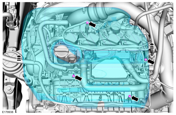
Remove the engine appearance cover.
 |
-
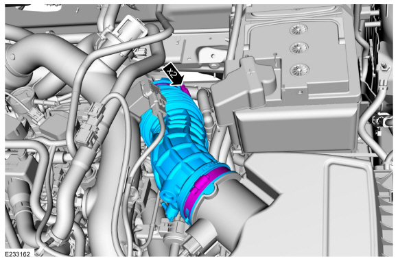
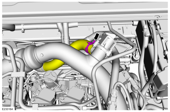
Loosen the clamp and position the upper air cleaner outlet pipe aside.
Torque: 44 lb.in (5 Nm)
 |
-
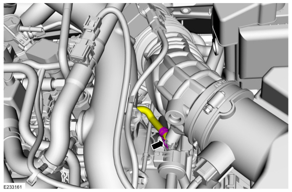
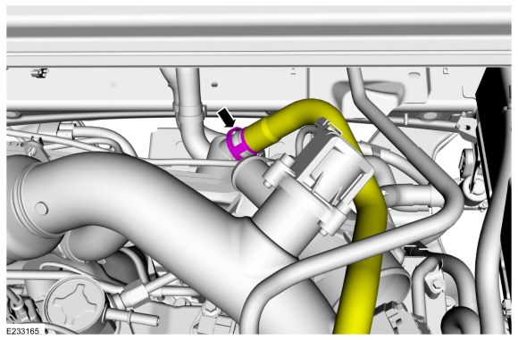
Release the clamp and disconnect the bypass valve hose.
Use the General Equipment: Hose Clamp Remover/Installer
 |
-
Disconnect the coupling.
 |
-
-
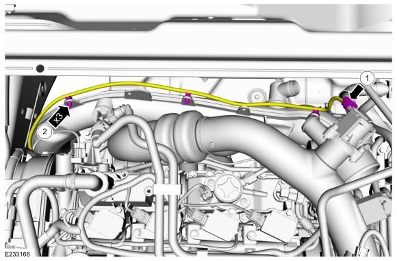
Disconnect the bypass valve electrical connector.
-
Detach the retainers and position the wire harness aside.
-
Disconnect the bypass valve electrical connector.
 |
-
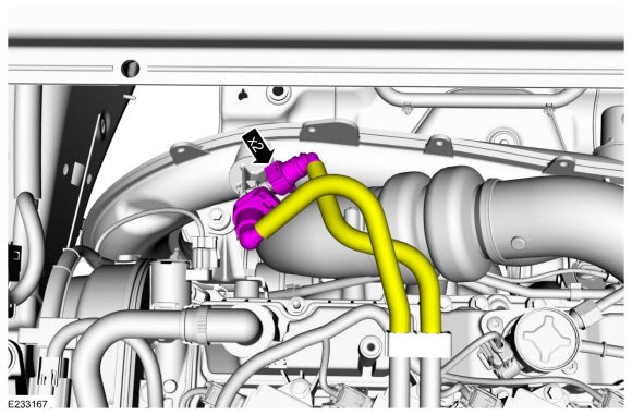
Disconnect the quick release couplings.
Refer to: Quick Release Coupling (310-00A Fuel System - General Information - 1.5L EcoBoost (118kW/160PS) – I4, General Procedures).
 |
-
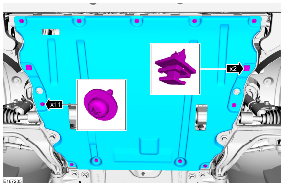
If equipped.
Remove the retainers and the underbody shield.
 |
-
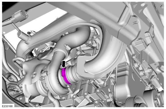
Loosen the clamp.
Torque: 44 lb.in (5 Nm)
 |
-
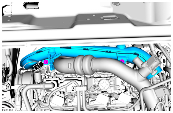
Remove the bolts and the lower air cleaner outlet pipe.
Torque: 97 lb.in (11 Nm)
 |
Installation
-
Inspect the turbocharger or engine air intake system components and clean, if necessary.
-
To install, reverse the removal procedure.
 Air Cleaner. Removal and Installation
Removal
NOTICE:
The turbocharger compressor vanes can be damaged by even the
smallest particles. When removing any turbocharger or engine air intake
system component, ensure that no debris enters the system...
 Charge Air Cooler (CAC) Coolant Pump. Removal and Installation
Special Tool(s) /
General Equipment
Hose Clamp(s)
Hose Clamp Remover/Installer
Materials
Name
Specification
Motorcraft® Orange Prediluted Antifreeze/CoolantVC-3DIL-B
WSS-M97B44-D2
Removal
NOTE:
Removal steps in this procedure may contain installation details...
Other information:
Ford Fusion 2013–2020 Service Manual: Front Door Tweeter Speaker. Removal and Installation
Removal NOTE: Removal steps in this procedure may contain installation details. Remove the front door trim panel. Refer to: Front Door Trim Panel (501-05 Interior Trim and Ornamentation, Removal and Installation). Release the tabs and remove the front door tweeter speaker...
Ford Fusion 2013–2020 Service Manual: Accessory Drive - Component Location. Description and Operation
Early Build Vehicles Item Description 1 Accessory drive belt tensioner 2 Water pump pulley 3 Crankshaft belt pulley 4 Pulley - A/C compressor 5 Drive belt idler pulley assembly 6 Generator pulley 7 Accessory drive belt Late Build Vehicles Item Description 1 Coolant pump pulley 2 Generator...
Categories
- Manuals Home
- 2nd Generation Ford Fusion Owners Manual
- 2nd Generation Ford Fusion Service Manual
- Powertrain
- Transmission - 1.5L EcoBoost (118kW/160PS) – I4. Removal and Installation
- Garage Door Opener
- New on site
- Most important about car
Manual Climate Control

Note: Depending on your vehicle option package, the controls may look different from what you see here.
Copyright © 2026 www.fofusion2.com