Ford Fusion: Intake Air Distribution and Filtering - 1.5L EcoBoost (118kW/160PS) – I4 / Charge Air Cooler (CAC) Coolant Pump. Removal and Installation
Ford Fusion 2013–2020 Service Manual / Powertrain / Engine / Intake Air Distribution and Filtering - 1.5L EcoBoost (118kW/160PS) – I4 / Charge Air Cooler (CAC) Coolant Pump. Removal and Installation
Special Tool(s) / General Equipment
| Hose Clamp(s) | |
| Hose Clamp Remover/Installer |
Materials
| Name | Specification |
|---|---|
| Motorcraft® Orange Prediluted Antifreeze/Coolant VC-3DIL-B |
WSS-M97B44-D2 |
Removal
NOTE: Removal steps in this procedure may contain installation details.
-
With the vehicle in N, position it on a hoist.
Refer to: Jacking and Lifting - Overview (100-02 Jacking and Lifting, Description and Operation).
-
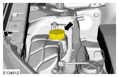
NOTE: When releasing the cooling system pressure, cover the coolant expansion tank cap with a thick cloth.
Loosen: 2 turn(s)
-
Tighten the cap.
Torque: 2 turn(s)
 |
-
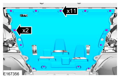
Remove the retainers and the engine undershield.
 |
-
-
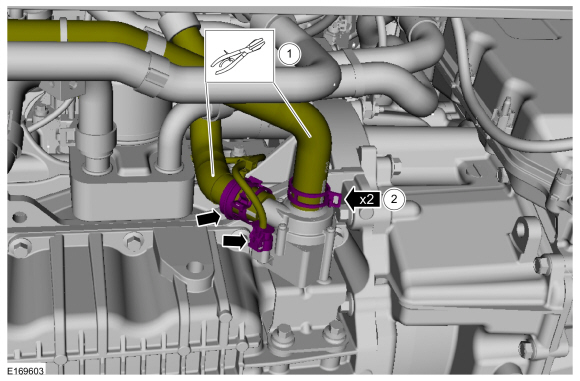
Clamp off the coolant hoses.
Use the General Equipment: Hose Clamp(s)
-
Detach the clip, disconnect the electrical connector and the coolant hoses.
Use the General Equipment: Hose Clamp Remover/Installer
-
Clamp off the coolant hoses.
 |
-
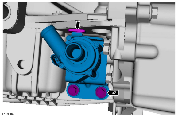
Remove the bolts, release the tab and remove the CAC coolant pump.
Torque: 97 lb.in (11 Nm)
 |
Installation
-
To install, reverse the removal procedure.
-
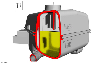
Check the coolant level in the degas bottle and add coolant as necessary.
Material: Motorcraft® Orange Prediluted Antifreeze/Coolant / VC-3DIL-B (WSS-M97B44-D2)
 |
 Air Cleaner Outlet Pipe. Removal and Installation
Special Tool(s) /
General Equipment
Hose Clamp Remover/Installer
Removal
NOTICE:
The turbocharger compressor vanes can be damaged by even the
smallest particles...
 Charge Air Cooler (CAC) Intake Pipe. Removal and Installation
Special Tool(s) /
General Equipment
Hose Clamp Remover/Installer
Removal
NOTICE:
The turbocharger compressor vanes can be damaged by even the
smallest particles...
Other information:
Ford Fusion 2013–2020 Owners Manual: Hints on Controlling the Interior Climate - Vehicles With: Automatic Temperature Control
General Hints Note: Prolonged use of recirculated air may cause the windows to fog up. Note: You may feel a small amount of air from the footwell air vents regardless of the air distribution setting. Note: To reduce humidity build-up inside your vehicle, do not drive with the system switched off or with recirculated air always switched on...
Ford Fusion 2013–2020 Service Manual: Seatbelt Systems. Diagnosis and Testing
Symptom Chart(s) Diagnostics in this manual assume a certain skill level and knowledge of Ford-specific diagnostic practices. REFER to: Diagnostic Methods (100-00 General Information, Description and Operation). Preliminary Inspection Before diagnosing or repairing the seatbelt system, inspect the following items: Seatbelt webbing integrity (torn, frayed, cut or stretched) Seat..
Categories
- Manuals Home
- 2nd Generation Ford Fusion Owners Manual
- 2nd Generation Ford Fusion Service Manual
- Main Control Valve Body. Removal and Installation
- Cylinder Head. Removal and Installation
- Powertrain
- New on site
- Most important about car
Direction Indicators. Interior Lamps
Direction Indicators
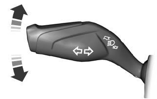
Push the lever up or down to use the direction indicators.
Copyright © 2026 www.fofusion2.com
