Ford Fusion: Intake Air Distribution and Filtering - 1.5L EcoBoost (118kW/160PS) – I4 / Charge Air Cooler (CAC) Intake Pipe. Removal and Installation
Special Tool(s) /
General Equipment
| Hose Clamp Remover/Installer |
Removal
NOTICE:
The turbocharger compressor vanes can be damaged by even the
smallest particles. When removing any turbocharger or engine air intake
system component, ensure that no debris enters the system. Failure to
do so may result in damage to the turbocharger.
NOTE:
Removal steps in this procedure may contain installation details.
-
With the vehicle in N, position it on a hoist.
Refer to: Jacking and Lifting - Overview (100-02 Jacking and Lifting, Description and Operation).
-
Remove the engine appearance cover.
-
-
Disconnect the crankcase pressure sensor electrical connector.
-
Unclip the retainer and position the wire harness aside.
-
-
Disconnect the turbocharger boost pressure sensor electrical connector.
-
Detach the retainers.
-
Detach the retainer and position the wire harness aside.
-
-
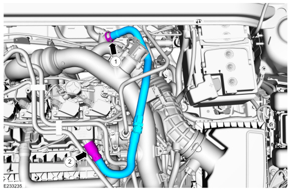
Disconnect the coupling.
-
Detach and remove the crankcase pressure sensor tube.
-
Disconnect the coupling and position the tube aside.
-
Disconnect the IAT2 sensor electrical connector.
-
-
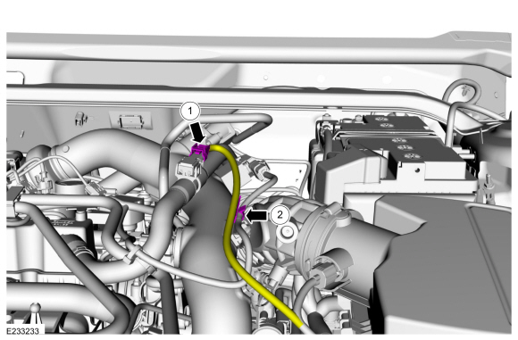
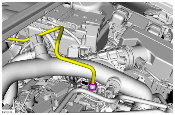
Disconnect the bypass valve electrical connector.
-
Release the clamp and disconnect the bypass valve tube.
Use the General Equipment: Hose Clamp Remover/Installer
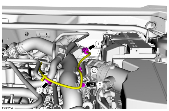
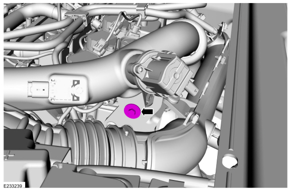
-
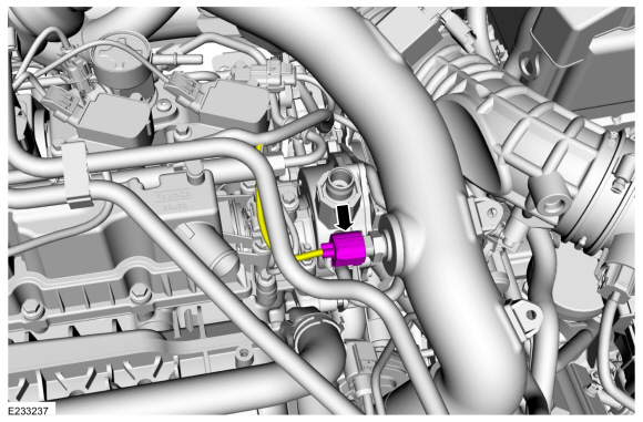
Remove the bolt.
Torque:
71 lb.in (8 Nm)
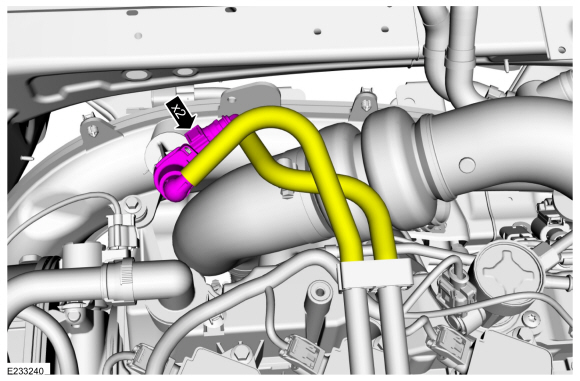
-
Disconnect the quick release couplings.
Refer to: Quick Release Coupling (310-00A Fuel System - General Information - 1.5L EcoBoost (118kW/160PS) – I4, General Procedures).
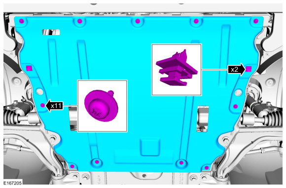
-
If equipped.
Remove the retainers and the underbody shield.
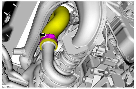
-
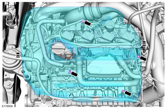
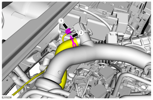
Loosen the clamp and disconnect the CAC intake tube.
Torque:
44 lb.in (5 Nm)
-
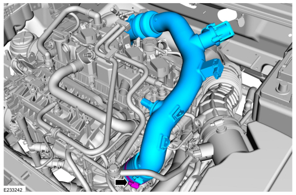
Loosen the clamp and remove the CAC intake pipe.
Torque:
44 lb.in (5 Nm)
Installation
-
Inspect the turbocharger or engine air intake system components and clean, if necessary.
-
To install, reverse the removal procedure.
Special Tool(s) /
General Equipment
Hose Clamp(s)
Hose Clamp Remover/Installer
Materials
Name
Specification
Motorcraft® Orange Prediluted Antifreeze/CoolantVC-3DIL-B
WSS-M97B44-D2
Removal
NOTE:
Removal steps in this procedure may contain installation details...
Special Tool(s) /
General Equipment
Cable Ties
Hose Clamp Remover/Installer
Removal
NOTE:
Removal steps in this procedure may contain installation details...
Other information:
Special Tool(s) /
General Equipment
Two Leg Puller
Removal
NOTE:
LH side shown, RH side similar.
Remove the wiper pivot arm nut cover and remove the wiper pivot arm nut.
Remove the wiper pivot arm...
DTC Chart
Diagnostics in this manual assume a certain skill level and knowledge of Ford-specific diagnostic practices. REFER to: Diagnostic Methods (100-00 General Information, Description and Operation).
BCM
DTC Chart
DTC
Description
Actions
B1323:11
Horn Switch: Circuit Short To Ground
GO to Pinpoint..
 Charge Air Cooler (CAC) Coolant Pump. Removal and Installation
 Charge Air Cooler (CAC) Radiator. Removal and Installation