Ford Fusion: Remote Convenience / Universal Transmitter. Diagnosis and Testing
Ford Fusion 2013–2020 Service Manual / Electrical / Electronic Feature Group / Remote Convenience / Universal Transmitter. Diagnosis and Testing
Symptom Chart(s)
Symptom Chart: Universal Home Transmitter
Diagnostics in this manual assume a certain skill level and knowledge of Ford-specific diagnostic practices.
REFER to: Diagnostic Methods (100-00 General Information, Description and Operation).
Symptom Chart
| Condition | Actions |
|---|---|
| The universal transmitter is inoperative | GO to Pinpoint Test A |
Pinpoint Tests
 PINPOINT TEST A : UNIVERSAL TRANSMITTER IS INOPERATIVE
|
Normal Operation and Fault Conditions
REFER to: Universal Transmitter - Overview (419-02 Remote Convenience, Description and Operation). Possible Sources
|
||||
| A1 CHECK FOR VOLTAGE TO THE UNIVERSAL TRANSMITTER | ||||
Does the indicator on the universal transmitter illuminate?
|
||||
| A2 PROGRAM A HAND-HELD TRANSMITTER TO THE UNIVERSAL TRANSMITTER | ||||
Does the universal transmitter program successfully?
|
||||
| A3 CHECK THE OPERATION OF THE LH (LEFT-HAND) VANITY MIRROR LAMP | ||||
Does the LH vanity mirror lamp operate correctly?
|
 Universal Transmitter - System Operation and Component Description. Description and Operation
System Operation
Universal Transmitter
The universal transmitter learns a hand-held transmitter radio
frequency code and stores the code in memory...
Other information:
Ford Fusion 2013–2020 Service Manual: Electronic Engine Controls - Overview. Description and Operation
Overview The EEC system provides optimum control of the engine through the enhanced capability of the powertrain control module (PCM). The EEC system also has an on board diagnostic (OBD) monitoring system with features and functions to meet federal regulations on exhaust emissions. The EEC system has two major divisions: hardware and software. The hardware includes the PCM, sensors, swit..
Ford Fusion 2013–2020 Service Manual: Specifications
Torque Specifications Item Nm lb-ft lb-in Lower Anchors and Tethers for Children (LATCH) bolts 48 35 - Lower Anchors and Tethers for Children (LATCH) nut 48 35 - ..
Categories
- Manuals Home
- 2nd Generation Ford Fusion Owners Manual
- 2nd Generation Ford Fusion Service Manual
- Front Controls Interface Module (FCIM). Removal and Installation
- Memory Function
- Electronic Parking Brake (EPB) Service Mode Activation and Deactivation. General Procedures
- New on site
- Most important about car
Fuel Quality
Choosing the Right Fuel

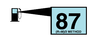
Your vehicle is designed to operate on regular unleaded gasoline with a minimum pump (R+M)/2 octane rating of 87.
Copyright © 2026 www.fofusion2.com

.jpg) PINPOINT TEST A : UNIVERSAL TRANSMITTER IS INOPERATIVE
PINPOINT TEST A : UNIVERSAL TRANSMITTER IS INOPERATIVE