
Ford Fusion: Electronic Feature Group / Cruise Control
- Cruise Control - Component Location. Description and Operation
- Cruise Control - Overview. Description and Operation
- Cruise Control - System Operation and Component Description. Description and Operation
- Cruise Control. Diagnosis and Testing
- Cruise Control Radar Alignment. General Procedures
- Cruise Control Module (CCM). Removal and Installation
 Universal Transmitter. Diagnosis and Testing
Symptom Chart(s)
Symptom Chart: Universal Home Transmitter
Diagnostics in this manual assume a certain skill level and knowledge of Ford-specific diagnostic practices...
 Cruise Control - Component Location. Description and Operation
Item
Description
1
CCM (adaptive cruise control only)
..
Other information:
Ford Fusion 2013–2020 Service Manual: Air Cleaner. Removal and Installation
Removal NOTICE: The turbocharger compressor vanes can be damaged by even the smallest particles. When removing any turbocharger or engine air intake system component, ensure that no debris enters the system. Failure to do so may result in damage to the turbocharger. NOTE: Removal steps in this procedure may contain installation details. Remove the bolts, disconnect th..
Ford Fusion 2013–2020 Service Manual: Instrument Panel and Interior Switches Illumination - Overview. Description and Operation
Overview Dimmable illumination provides backlighting to switches and control components when the parking lamps are on or a set level of intensity when the ignition is on for non-dimmable components. The level of intensity for the dimmable backlit components is adjusted by pressing the instrument panel dimmer switch up to increase intensity or down to decrease intensity. The illumination so..
Categories
- Manuals Home
- 2nd Generation Ford Fusion Owners Manual
- 2nd Generation Ford Fusion Service Manual
- Traction Control
- Cylinder Head. Removal and Installation
- Under Hood Overview - 1.5L EcoBoost™, 2.0L EcoBoost™, 2.5L, 2.7L EcoBoost™
- New on site
- Most important about car
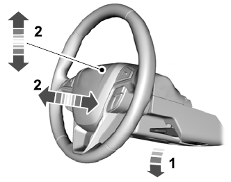
Adjusting the Steering Wheel
WARNING: Do not adjust the steering wheel when your vehicle is moving.
Note: Make sure that you are sitting in the correct position.

Copyright © 2026 www.fofusion2.com