Ford Fusion: Automatic Transmission - 6-Speed Automatic Transmission – 6F35 / Transmission Air Pressure Test. Diagnosis and Testing
Transmission Air Pressure Test
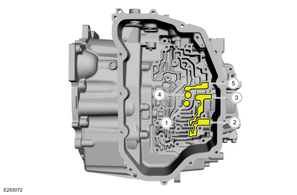
| Item | Description |
| 1 | Foward clutch |
| 2 | Direct clutch |
| 3 | Intermediate clutch |
| 4 | Low reverse clutch |
| 5 | Overdrive clutch |
NOTE: The center support contains an air bleed for the forward and Low reverse clutch circuits. Some leakage during the air test can be normal.
NOTE: The Intermediate clutch pressure chamber contains an air bleed for the Intermediate clutch circuit. Some leakage during the air test can be normal.
A hydraulic clutch concern can be located through a series of checks by substituting air pressure for fluid pressure to determine the location of the concern.
-
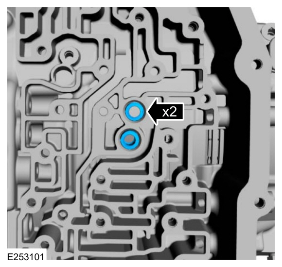
Install the forward clutch and low/reverse clutch main control-to-transmission case seals.
-
Using a rubber tipped blow gun, apply 40 PSI (276 kpa) to the suspect clutch port for 2-3 seconds.
-
A dull thud indicates the clutch piston applied.
-
A hissing noise may indicate a leak in the hydraulic
passages. Hydraulic circuits that use scarf cut seals and/or air bleeds
will have some normal leakage.
-
A dull thud indicates the clutch piston applied.
-
While holding the blow gun nozzle firmly against the port in the transmission case, release the trigger.
-
Wait 1-2 seconds.
-
A hissing noise may indicate a leak in the hydraulic
passages. Hydraulic circuits that use scarf cut seals and/or air bleeds
will have some normal leakage.
-
A hissing noise may indicate a leak in the hydraulic
passages. Hydraulic circuits that use scarf cut seals and/or air bleeds
will have some normal leakage.
-
Remove the blow gun from the port.
-
A sudden release of air pressure indicates the hydraulic passages are capable of holding pressure.
-
No noise may indicate a leak in the hydraulic passages.
Hydraulic circuits that use scarf cut seals and/or air bleeds will have
some normal leakage.
-
A sudden release of air pressure indicates the hydraulic passages are capable of holding pressure.
 Diagnosis By Symptom. Diagnosis and Testing
Symptom Chart(s)
Symptom Chart: Automatic Transmission
Diagnostics in this manual assume a certain skill level and knowledge of Ford-specific diagnostic practices...
 Transmission Line Pressure Test. Diagnosis and Testing
Line Pressure Test
NOTE:
Perform the line pressure test prior to performing the stall
speed test. If the line pressure is low at stall, do not perform the
stall speed test or transmission damage will occur...
Other information:
Ford Fusion 2013–2020 Service Manual: Climate Control System Health and Safety Precautions. Description and Operation
WARNING: Air conditioning liquid refrigerant R-134a and R-1234yf are capable of harming eyes or freezing skin. Always wear safety goggles and avoid contact with liquid refrigerant. Failure to follow these instructions may result in serious personal injury...
Ford Fusion 2013–2020 Service Manual: Module Controlled Functions - System Operation and Component Description. Description and Operation
System Operation Battery Saver The battery saver feature is use to save battery voltage. The BCM provides automatic shut-off of the interior and exterior lamps after a time-out period when the ignition is off. For more information regarding the exterior lighting battery saver feature, Refer to: Exterior Lighting (417-01 Exterior Lighting) ...
Categories
- Manuals Home
- 2nd Generation Ford Fusion Owners Manual
- 2nd Generation Ford Fusion Service Manual
- Engine - 1.5L EcoBoost (118kW/160PS) – I4
- Body Control Module (BCM). Removal and Installation
- Front Controls Interface Module (FCIM). Removal and Installation
- New on site
- Most important about car
Using Seatbelts During Pregnancy
WARNING: Always ride and drive with your seatback upright and properly fasten your seatbelt. Fit the lap portion of the seatbelt snugly and low across the hips. Position the shoulder portion of the seatbelt across your chest. Pregnant women must follow this practice. See the following figure.
