Ford Fusion: Information and Entertainment System - General Information - Vehicles With: SYNC 3 / SYNC Module [APIM] to Universal Serial Bus (USB) Port Cable - Police. Removal and Installation
Ford Fusion 2013–2020 Service Manual / Electrical / Information and Entertainment Systems / Information and Entertainment System - General Information - Vehicles With: SYNC 3 / SYNC Module [APIM] to Universal Serial Bus (USB) Port Cable - Police. Removal and Installation
Special Tool(s) / General Equipment
| Interior Trim Remover |
Removal
NOTE: Removal steps in this procedure may contain installation details.
-
Remove the retainer, release the clips, disconnect the electrical connector and remove the LH center instrument panel trim panel.
Use the General Equipment: Interior Trim Remover
![Ford Fusion. SYNC Module [APIM] to Universal Serial Bus (USB) Port Cable - Police. Removal and Installation](images/sync_module_apim_to_universal_serial_bus_usb_port_cable_police_removal_and_installation-2576/1942/ford_fusion__sync_module_apim_to_universal_serial_bus_usb_port_cable_police_removal_and_installation_6140.jpg) |
-
Remove the retainer, release the clips and remove the RH center instrument panel trim panel.
Use the General Equipment: Interior Trim Remover
![Ford Fusion. SYNC Module [APIM] to Universal Serial Bus (USB) Port Cable - Police. Removal and Installation](images/sync_module_apim_to_universal_serial_bus_usb_port_cable_police_removal_and_installation-2576/1942/ford_fusion__sync_module_apim_to_universal_serial_bus_usb_port_cable_police_removal_and_installation_6141.jpg) |
-
Release the clips and remove the center lower trim panel.
![Ford Fusion. SYNC Module [APIM] to Universal Serial Bus (USB) Port Cable - Police. Removal and Installation](images/sync_module_apim_to_universal_serial_bus_usb_port_cable_police_removal_and_installation-2576/1942/ford_fusion__sync_module_apim_to_universal_serial_bus_usb_port_cable_police_removal_and_installation_6142.jpg) |
-
Release the clips and remove the FCIM bezel.
Use the General Equipment: Interior Trim Remover
![Ford Fusion. SYNC Module [APIM] to Universal Serial Bus (USB) Port Cable - Police. Removal and Installation](images/sync_module_apim_to_universal_serial_bus_usb_port_cable_police_removal_and_installation-2576/1942/ford_fusion__sync_module_apim_to_universal_serial_bus_usb_port_cable_police_removal_and_installation_6143.jpg) |
-
Release the clips, disconnect the electrical connectors and remove the GSM bezel.
Use the General Equipment: Interior Trim Remover
![Ford Fusion. SYNC Module [APIM] to Universal Serial Bus (USB) Port Cable - Police. Removal and Installation](images/sync_module_apim_to_universal_serial_bus_usb_port_cable_police_removal_and_installation-2576/1942/ford_fusion__sync_module_apim_to_universal_serial_bus_usb_port_cable_police_removal_and_installation_6144.jpg) |
-
Remove the screws, disconnect the electrical connectors and remove the GSM.
![Ford Fusion. SYNC Module [APIM] to Universal Serial Bus (USB) Port Cable - Police. Removal and Installation](images/sync_module_apim_to_universal_serial_bus_usb_port_cable_police_removal_and_installation-2576/1942/ford_fusion__sync_module_apim_to_universal_serial_bus_usb_port_cable_police_removal_and_installation_6145.jpg) |
-
RH side is shown, LH side is similar.
Remove the center instrument panel support.
-
Remove the screws.
Torque: 22 lb.in (2.5 Nm)
-
Remove the bolt.
Torque: 55 lb.in (6.2 Nm)
-
Separate the wiring harness guides.
-
Remove the screws.
![Ford Fusion. SYNC Module [APIM] to Universal Serial Bus (USB) Port Cable - Police. Removal and Installation](images/sync_module_apim_to_universal_serial_bus_usb_port_cable_police_removal_and_installation-2576/1942/ford_fusion__sync_module_apim_to_universal_serial_bus_usb_port_cable_police_removal_and_installation_6146.jpg) |
-
Disconnect the electrical connector, separate the cable guides and remove the APIM to USB port cable.
![Ford Fusion. SYNC Module [APIM] to Universal Serial Bus (USB) Port Cable - Police. Removal and Installation](images/sync_module_apim_to_universal_serial_bus_usb_port_cable_police_removal_and_installation-2576/1942/ford_fusion__sync_module_apim_to_universal_serial_bus_usb_port_cable_police_removal_and_installation_6147.jpg) |
Installation
-
To install, reverse the removal procedure.
 SYNC Module [APIM] to Universal Serial Bus (USB) Port Cable. Removal and Installation
Special Tool(s) /
General Equipment
Interior Trim Remover
Removal
NOTE:
Removal steps in this procedure may contain installation details...
 Telematics Control Unit (TCU) Module. Removal and Installation
Removal
NOTE:
Removal steps in this procedure may contain installation details.
NOTE:
If installing a new module, it is necessary to
upload the module configuration information to the scan tool prior to
removing the module...
Other information:
Ford Fusion 2013–2020 Service Manual: Headlamp Bulb. Removal and Installation
Removal NOTE: The procedure for the LH headlamp assembly is shown, the RH headlamp assembly is similar. NOTE: Removal steps in this procedure may contain installation details. Low beam headlamp bulb NOTE: LH is shown, RH is similar...
Ford Fusion 2013–2020 Owners Manual: Refueling System Warning (If Equipped)
If the fuel tank filler valve does not fully close, a message could appear in the information display. If the message appears, do the following: Stop your vehicle as soon as it is safe to do so and switch the engine off. Shift into park (P) or neutral (N)...
Categories
- Manuals Home
- 2nd Generation Ford Fusion Owners Manual
- 2nd Generation Ford Fusion Service Manual
- Under Hood Overview - 1.5L EcoBoost™, 2.0L EcoBoost™, 2.5L, 2.7L EcoBoost™
- Load Carrying
- Transmission - 1.5L EcoBoost (118kW/160PS) – I4. Removal and Installation
- New on site
- Most important about car
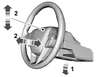
Adjusting the Steering Wheel
WARNING: Do not adjust the steering wheel when your vehicle is moving.
Note: Make sure that you are sitting in the correct position.

Copyright © 2025 www.fofusion2.com
