Ford Fusion: Suspension System - General Information / Suspension System. Diagnosis and Testing
Preliminary Inspection
-
Road test the vehicle.
-
If any suspension alignment or ride height concerns are present, REFER to Symptom Chart: Suspension System.
-
Verify the customer concern by carrying out a road test
on a smooth road. If any vibrations are present, REFER to Symptom Chart:
NVH.
-
If any suspension alignment or ride height concerns are present, REFER to Symptom Chart: Suspension System.
-
Inspect the tires.
-
Check the tire pressures with all normal loads in the vehicle and the tires cold. REFER to the VC label.
-
Verify that all tires are sized to specification. REFER to the VC label.
-
Inspect the tires for incorrect wear and damage. INSTALL new tires as necessary.
-
Check the tire pressures with all normal loads in the vehicle and the tires cold. REFER to the VC label.
-
Inspect the chassis and underbody.
-
Remove any excessive accumulation of mud, dirt or road deposits from the chassis and underbody.
-
Front or rear suspension components.
-
Suspension fastener(s).
-
Incorrect spring usage Spring(s).
-
Shock absorber(s).
-
Strut(s).
-
Suspension bushing(s).
-
Steering system components.
-
Wheel bearing and wheel hub(s).
-
Remove any excessive accumulation of mud, dirt or road deposits from the chassis and underbody.
-
Inspect for aftermarket equipment.
-
Check for aftermarket changes to the steering,
suspension, and wheel and tire components (such as competition or heavy
duty). The specifications shown in this manual do not apply to vehicles
equipped with aftermarket equipment.
-
Check for aftermarket changes to the steering,
suspension, and wheel and tire components (such as competition or heavy
duty). The specifications shown in this manual do not apply to vehicles
equipped with aftermarket equipment.
Symptom Chart: Suspension System
Diagnostics in this manual assume a certain skill level and knowledge of Ford-specific diagnostic practices.
REFER to: Diagnostic Methods (100-00 General Information, Description and Operation).
| Condition | Possible Sources | Actions |
|---|---|---|
| Vehicle drifts/pulls | Refer to the Diagnostic Routine. | GO to Pinpoint Test A |
| Wander | Overloaded, unevenly or incorrectly loaded vehicle | NOTIFY the customer of incorrect vehicle loading. |
| Ball joint(s) |
CARRY OUT a ball joint inspection. REFER to: Suspension System (204-00 Suspension System - General Information, Diagnosis and Testing). INSTALL new control arm(s) as necessary. REFER to: Lower Arm (204-01 Front Suspension, Removal and Installation). |
|
| Damaged or missing front strut mount bearing(s) |
INSTALL a new front strut mount bearing(s) as necessary. REFER to: Front Strut and Spring Assembly (204-01 Front Suspension, Removal and Installation). |
|
| Loose, worn or damaged front wheel bearing(s) |
INSPECT the wheel bearings. INSTALL new wheel bearings as necessary. REFER to: Front Wheel Bearing and Wheel Hub (204-01 Front Suspension, Removal and Installation). |
|
| Loose, worn or damaged suspension component(s) | INSTALL new suspension component(s) as necessary. | |
| Loose suspension fasteners | INSPECT the suspension fasteners. TIGHTEN to specifications. | |
| Steering components | INSPECT the steering system. INSTALL new components as necessary. | |
| Wheel alignment (excessive total front toe out) |
ADJUST as necessary. Toe Adjustment - Front REFER to: Front Toe Adjustment (204-00 Suspension System - General Information, General Procedures). or Toe Adjustment - Rear REFER to: Rear Toe Adjustment (204-00 Suspension System - General Information, General Procedures). |
|
| Front bottoming or riding low | Worn, damaged or incorrect springs |
MEASURE the ride height. REFER to: Ride Height Measurement (204-00 Suspension System - General Information, General Procedures). INSTALL new springs as necessary. REFER to: Front Strut and Spring Assembly (204-01 Front Suspension, Removal and Installation). |
| Worn front strut(s) |
INSTALL new struts as necessary. REFER to: Front Strut and Spring Assembly (204-01 Front Suspension, Removal and Installation). |
|
| Abnormal/incorrect tire wear | Incorrect tire pressure (rapid center rib or inner and outer edge wear) | ADJUST the tire pressure. REFER to VC label. |
| Incorrect tire rotation intervals |
REFER to: Maintenance Schedules - Gasoline Engines (100-03 Maintenance Schedules, Description and Operation). |
|
|
REFER to: Wheel and Tire (204-04A Wheels and Tires, Removal and Installation). |
|
| Front or rear suspension components | INSPECT the front and rear suspension system. REPAIR or INSTALL new suspension components as necessary. | |
| Sticky steering, poor returnability | Damaged or worn front strut mount bearing(s) |
INSTALL a new front strut mount bearing(s) as necessary. REFER to: Front Strut and Spring Assembly (204-01 Front Suspension, Removal and Installation). |
| Binding ball joints |
CARRY OUT a ball joint inspection. REFER to: Suspension System (204-00 Suspension System - General Information, Diagnosis and Testing). INSTALL new control arm(s) as necessary.REFER to: Lower Arm (204-01 Front Suspension, Removal and Installation). |
|
| Steering components |
INSPECT the steering system. INSTALL new components as necessary. REFER to: Power Steering (211-02 Power Steering, Diagnosis and Testing). |
|
| Steering wheel off-center | Unequal front or rear toe setting (side-to-side) |
CHECK the wheel alignment. REFER to: Front Toe Adjustment (204-00 Suspension System - General Information, General Procedures). or Toe Adjustment - Rear REFER to: Rear Toe Adjustment (204-00 Suspension System - General Information, General Procedures). |
| Steering components |
INSPECT the steering system. INSTALL new components as necessary. REFER to: Power Steering (211-02 Power Steering, Diagnosis and Testing). |
|
| Sway or roll | Overloaded, unevenly or incorrectly loaded vehicle | NOTIFY the customer of incorrect vehicle loading. |
| Loose wheel nut(s) |
TIGHTEN the wheel nut(s) to specification. REFER to: Wheel and Tire (204-04A Wheels and Tires, Removal and Installation). |
|
| Strut(s) or shock absorber(s) |
INSTALL new struts or shock absorbers as necessary. REFER to: Front Strut and Spring Assembly (204-01 Front Suspension, Removal and Installation). or REFER to: Rear Shock Absorber (204-02 Rear Suspension, Removal and Installation). |
|
| Loose stabilizer bracket-to-frame bolts |
TIGHTEN the bolts to specification. REFER to: Front Stabilizer Bar (204-01 Front Suspension, Removal and Installation). |
|
| Worn stabilizer bar bushings or links |
INSTALL new stabilizer bar bushings or links as necessary. REFER to: Front Stabilizer Bar (204-01 Front Suspension, Removal and Installation). or REFER to: Front Stabilizer Bar Link (204-01 Front Suspension, Removal and Installation). |
|
| Damaged or broken stabilizer bar |
INSTALL a new stabilizer bar as necessary. REFER to: Front Stabilizer Bar (204-01 Front Suspension, Removal and Installation). |
|
| Worn spring(s) |
INSTALL new springs as necessary. REFER to: Front Strut and Spring Assembly (204-01 Front Suspension, Removal and Installation). or REFER to: Spring (204-02 Rear Suspension, Removal and Installation). |
|
| Vehicle leans to one side | Unevenly loaded or overloaded vehicle | NOTIFY the customer of incorrect vehicle loading. |
| Front or rear suspension components | INSPECT the front and rear suspension systems. INSTALL new suspension components as necessary. | |
| Incorrect drive axle(s) ride height. Side-to-side lean out of specification |
MEASURE the ride height. REFER to: Ride Height Measurement (204-00 Suspension System - General Information, General Procedures). INSPECT the front and rear suspension systems. REPAIR or INSTALL new components as necessary |
- If an obvious cause for an observed or reported condition is found, correct the cause (if possible) before proceeding to the next step.
- If the fault is not visually evident, REFER to Symptom Chart or REFER to Symptom Chart: NVH.
Symptom Chart: NVH
Diagnostics in this manual assume a certain skill level and knowledge of Ford-specific diagnostic practices.
REFER to: Diagnostic Methods (100-00 General Information, Description and Operation).
Noise,
Vibration, or Harshness (NVH) symptoms should be identified using the
diagnostic tools that are available. For a list of these tools, an
explanation of their uses and a glossary of common terms, Glossary of
Terms
REFER to: Noise, Vibration and Harshness (NVH) (100-04 Noise, Vibration and Harshness, Description and Operation).
Since it is possible any one of multiple systems may be the cause of a
symptom, it may be necessary to use a process of elimination type of
diagnostic approach to pinpoint the responsible system. If this is not
the causal system for the symptom,REFER to: Noise, Vibration and Harshness (NVH) (100-04 Noise, Vibration and Harshness, Diagnosis and Testing).
for the next likely system and continue diagnosis.
| Condition | Possible Sources | Actions |
|---|---|---|
| Squeak or grunt - noise from the suspension | Front or rear suspension components | INSPECT the front or rear suspension. INSTALL new components as necessary. |
| Clunk - noise from the front suspension, occurs in and out of turns | Loose front suspension | INSPECT for loose nuts or bolts. TIGHTEN to specifications. |
| Clunk - noise from the rear suspension, occurs when shifting from REVERSE to DRIVE | Loose rear suspension components | INSPECT for loose or damaged rear suspension components. REPAIR or INSTALL new components as necessary. |
| Click or pop - noise from the front suspension. More noticeable over rough roads or over bumps | Worn or damaged ball joint(s) |
CARRY OUT a ball joint inspection. REFER to: Suspension System (204-00 Suspension System - General Information, Diagnosis and Testing). INSTALL new control arm(s) as necessary. REFER to: Lower Arm (204-01 Front Suspension, Removal and Installation). |
| Front suspension noise - a squeak, creak or rattle noise. Occurs mostly over bumps or rough roads |
|
INSPECT the front suspension. INSTALL new components as necessary. |
| Rear suspension noise - a squeak, creak or rattle noise. Occurs mostly over bumps or rough roads |
|
INSPECT the rear suspension. INSTALL new components as necessary. |
| Shimmy | Loose wheel nut(s) |
TIGHTEN the nut(s) to specification. REFER to: Wheel and Tire (204-04A Wheels and Tires, Removal and Installation). |
| Loose front suspension fastener(s) | TIGHTEN the fastener(s) to specifications. | |
| Loose front wheel bearing(s) |
INSPECT the front wheel bearing(s). INSTALL new bearing(s) as necessary. REFER to: Front Wheel Bearing and Wheel Hub (204-01 Front Suspension, Removal and Installation). |
|
| Strut(s) or shock absorber(s) |
INSTALL new struts or shock absorbers as necessary. REFER to: Front Strut and Spring Assembly (204-01 Front Suspension, Removal and Installation). or REFER to: Rear Shock Absorber (204-02 Rear Suspension, Removal and Installation). |
|
| Shimmy - most noticeable on coast/deceleration. Also hard steering condition | Excessive positive caster | INSPECT the front suspension. REPAIR or INSTALL new suspension components as necessary. |
| Rough/harsh ride | Incorrect tire pressure | ADJUST the tire pressure. REFER to VC label. |
| Low ride height |
MEASURE the ride height. REFER to: Ride Height Measurement (204-00 Suspension System - General Information, General Procedures). INSTALL new springs as necessary. REFER to: Front Strut and Spring Assembly (204-01 Front Suspension, Removal and Installation). or REFER to: Spring (204-02 Rear Suspension, Removal and Installation). |
|
| Loose, worn or damaged suspension component(s) | INSTALL new suspension component(s) as necessary. |
Pinpoint Tests
Vehicle Drifts, Pulls
Diagnostic Overview
Diagnostics in this manual assume a certain skill level and knowledge of Ford-specific diagnostic practices.
REFER to: Diagnostic Methods (100-00 General Information, Description and Operation).
Possible Causes
- Unevenly loaded vehicle
- Tire pressure
- Tire forces
- Brake drag
- Incorrect vehicle alignment
- Bent/damaged vehicle components
- Steering system
PINPOINT TEST A : VEHICLE DRIFTS, PULLS
| A1 CHECK FOR UNEVENLY LOADED VEHICLE | ||||
Is the vehicle unevenly loaded?
|
||||
| A2 CHECK THE TIRE PRESSURES AND TIRE CONDITIONS | ||||
Are the tire pressures and tire conditions OK?
|
||||
| A3 ISOLATE TIRE DRIFT/PULL CONDITION | ||||
Does the vehicle drift/pull?
|
||||
| A4 CHECK FOR BRAKE DRAG | ||||
Do the wheels spin freely?
|
||||
| A5 CHECK THE WHEEL ALIGNMENT | ||||
Is the wheel alignment out of specification?
|
Component Tests
Ball Joint Inspection
-
Prior to inspecting the ball joints for wear, inspect
the wheel bearings. Install a new wheel bearing as necessary.
REFER to: Front Wheel Bearing and Wheel Hub (204-01 Front Suspension, Removal and Installation).
-
NOTE: In order to obtain accurate measurements, the suspension must be in full rebound with the weight of the vehicle supported by the frame.
Raise and support the vehicle by the frame to allow the wheels to hang in the rebound position.
REFER to: Jacking and Lifting - Overview (100-02 Jacking and Lifting, Description and Operation).
-
Inspect the ball joint and ball joint boot for damage.
-
If the ball joint or ball joint boot is damaged, install a new lower control arm as necessary.
REFER to: Lower Arm (204-01 Front Suspension, Removal and Installation).
-
If the ball joint or ball joint boot is damaged, install a new lower control arm as necessary.
-
NOTICE: Do not use any tools or equipment to move the wheel and tire assembly or suspension components while checking for relative movement. Suspension damage may occur. The use of tools or equipment will also create relative movement that may not exist when using hand force. Relative movement must be measured using hand force only.
Inspect the ball joint for relative movement by alternately pulling downward and pushing upward on the lower control arm by hand. Note any relative vertical movement between the wheel knuckle and lower control arm at the lower ball joint.
-
If relative movement is not felt or seen, the ball joint is OK. Do not install a new lower control arm.
-
If relative movement is found, continue with Step 5.
-
If relative movement is not felt or seen, the ball joint is OK. Do not install a new lower control arm.
-
NOTE: In order to obtain an accurate measurement, the dial indicator should be aligned as close as possible with the vertical axis (center line) of the ball joint.
To measure ball joint deflection, attach a suitable dial indicator with a flexible arm between the lower control arm and the wheel knuckle or ball joint stud.
-
Measure the ball joint deflection while an assistant pushes up and pulls down on the lower control arm, by hand.
-
If the deflection exceeds the specification, a new lower control arm must be installed.
REFER to: Lower Arm (204-01 Front Suspension, Removal and Installation).
-
If the deflection meets the specification, no further action is required.
-
If the deflection exceeds the specification, a new lower control arm must be installed.
 Specifications
General Specifications
Item
Specification
Ball Joint Deflection
Lower
0.0 mm (0.0 in) - 0...
 Front Toe Adjustment. General Procedures
Special Tool(s) /
General Equipment
Wheel Alignment System
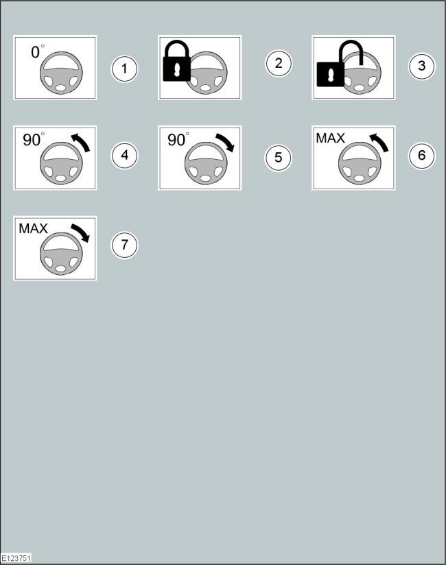
Adjustment
NOTE:
Make sure that the vehicle is standing on a level surface.
Steering wheel in straight ahead position...
Other information:
Ford Fusion 2013–2020 Service Manual: Engine. Removal
Special Tool(s) / General Equipment 300-OTC1585AEPowertrain Lift 300-OTC1819E2,200# Floor Crane, Fold Away 303-1502Lifting Device EngineTKIT-2012A-FLTKIT-2012A-ROW 307-569Disconnect Tool TOC Line (1/2)TKIT-2006U-F/FMTKIT-2006U-FLM/LMTKIT-2006U-ROW1TKIT-2006U-ROW2 Strap Wrench Adjustable Mounting Arm Oil Drain Equipment Hose Clamp Remover/Installer ..
Ford Fusion 2013–2020 Owners Manual: Setting the Gap Distance
You can decrease or increase the distance between your vehicle and the vehicle in front by pressing the gap control. Press and release to decrease the gap distance. Press and release to increase the gap distance. The selected gap appears in the information display as shown by the bars in the image. Note: The gap setting is time dependent and therefore the distance adjusts with your ve..
Categories
- Manuals Home
- 2nd Generation Ford Fusion Owners Manual
- 2nd Generation Ford Fusion Service Manual
- Cylinder Head. Removal and Installation
- Automatic Transmission Fluid Check - 1.5L EcoBoost™/2.0L EcoBoost™/2.5L. Automatic Transmission Fluid Check - 2.7L EcoBoost™
- Electronic Parking Brake (EPB) Service Mode Activation and Deactivation. General Procedures
- New on site
- Most important about car
Power Door Locks
The power door lock control is on the driver and front passenger door panels.