Ford Fusion: Rear End Sheet Metal Repairs / Spare Tire Bracket. Removal and Installation
Special Tool(s) / General Equipment
| 8 mm Drill Bit | |
| MIG/MAG Welding Equipment | |
| Spot Weld Drill Bit | |
| Locking Pliers |
Removal
NOTICE: Battery electric vehicle (BEV), hybrid electric vehicle (HEV) and plug-in hybrid electric vehicle (PHEV) contain a high-voltage battery. Before cutting or welding near the high-voltage battery it must be removed to avoid damage.
NOTE: Factory welds may be substituted with resistance or metal inert gas (MIG) plug welds. Resistance welds may not be placed directly over original location. They must be placed adjacent to original location and match factory welds in quantity. Metal inert gas (MIG) plug welds must equal factory welds in both location and quantity.
NOTE: Adequately protect all adjacent areas against cutting, grinding and welding procedures.
-
Remove the luggage compartment trim and spare tire.
-
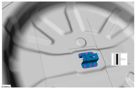
Remove the welds and the spare tire retaining bracket.
Use the General Equipment: Spot Weld Drill Bit
 |
Installation
NOTICE: Battery electric vehicle (BEV), hybrid electric vehicle (HEV) and plug-in hybrid electric vehicle (PHEV) contain a high-voltage battery. Before cutting or welding near the high-voltage battery it must be removed to avoid damage.
NOTICE: The high-voltage battery in a battery electric vehicle (BEV), hybrid electric vehicle (HEV) or plug-in hybrid electric vehicle (PHEV) can be affected and damaged by excessively high temperatures. The temperature in some body shop paint booths can exceed 60° C (140° F). Therefore, during refinishing operations, the paint booth temperature must set at or below 60° C (140° F) with a bake time of 45 minutes or less. Temperatures in excess of 60° C (140° F) or bake durations longer than 45 minutes will require the high-voltage battery be removed from the vehicle prior to placing in the paint booth.
NOTICE: If refinishing cure temperatures exceed 60° C (140° F), the charge port light ring on plug-in vehicles must be removed.
NOTE: Factory welds may be substituted with resistance or metal inert gas (MIG) plug welds. Resistance welds may not be placed directly over original location. They must be placed adjacent to original location and match factory welds in quantity. Metal inert gas (MIG) plug welds must equal factory welds in both location and quantity.
NOTE: Adequately protect all adjacent areas against cutting, grinding and welding procedures.
-
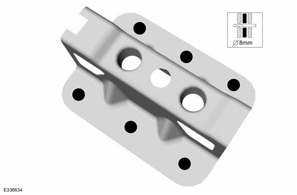
Drill plug weld holes in the replacement spare tire bracket.
Use the General Equipment: 8 mm Drill Bit
 |
-
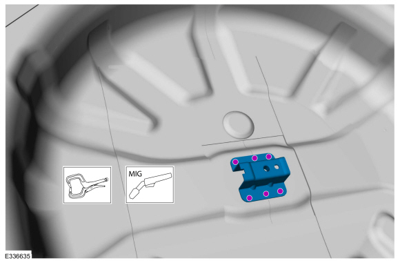
Install, properly position, clamp and weld the spare tire bracket.
Use the General Equipment: Locking Pliers
Use the General Equipment: MIG/MAG Welding Equipment
 |
-
Refinish the entire repair using a Ford approved paint system.
-
Restore corrosion protection.
Refer to: Corrosion Prevention (501-25 Body Repairs - General Information, General Procedures).
-
Install the spare tire and luggage compartment trim.
 Rear Wheelhouse Outer. Removal and Installation
Special Tool(s) /
General Equipment
Resistance Spotwelding Equipment
Air Body Saw
Materials
Name
Specification
Seam SealerTA-2-B, 3M™ 08308, LORD Fusor® 803DTM
-
Removal
WARNING:
Before beginning any service procedure in this
section, refer to Safety Warnings in section 100-00 General Information...
 Water Drain Panel. Removal and Installation
Special Tool(s) /
General Equipment
Resistance Spotwelding Equipment
8 mm Drill Bit
MIG/MAG Welding Equipment
Spot Weld Drill Bit
Locking Pliers
Materials
Name
Specification
Seam SealerTA-2-B, 3M™ 08308, LORD Fusor® 803DTM
-
Removal
NOTICE:
Battery electric vehicle (BEV), hybrid electric vehicle
(HEV) and plug-in hybrid electric vehicle ..
Other information:
Ford Fusion 2013–2020 Service Manual: Instrument Panel Cluster (IPC) - System Operation and Component Description. Description and Operation
System Operation System Diagram - Gauges Item Description 1 Base/mid-level 2 High-level 3 Base/mid-level 4 High-level 5 Base/mid-level 6 High-level 7 Base/mid-level 8 High-level 9 AWD 10 Temperature 11 Tachometer 12 HS-CAN1 13 IPC 14 GWM 15 PCM 16 HS-CAN3 ..
Ford Fusion 2013–2020 Service Manual: Power Transfer Unit - Overview. Description and Operation
The AWD system consists of the following: Power Transfer Unit (PTU) Rear driveshaft AWD control module Rear axle with coupling device The Power Transfer Unit (PTU) is a gearbox that attaches to the transmission. The PTU directs power to the rear driveshaft through a helical gear spline coupled to the transmission differential case and hypoid/helical ring gear assembl..
Categories
- Manuals Home
- 2nd Generation Ford Fusion Owners Manual
- 2nd Generation Ford Fusion Service Manual
- Pre-Collision Assist (IF EQUIPPED)
- Starter Motor. Removal and Installation
- Under Hood Overview - 1.5L EcoBoost™, 2.0L EcoBoost™, 2.5L, 2.7L EcoBoost™
- New on site
- Most important about car
Direction Indicators. Interior Lamps
Direction Indicators

Push the lever up or down to use the direction indicators.