Ford Fusion: Automatic Transmission - 6-Speed Automatic Transmission – 6F35 / Solenoid. Removal and Installation
Ford Fusion 2013–2020 Service Manual / Powertrain / Automatic Transmission / Automatic Transmission - 6-Speed Automatic Transmission – 6F35 / Solenoid. Removal and Installation
Special Tool(s) / General Equipment
| Long Nose Pliers |
Removal
-
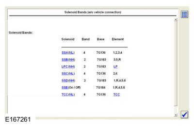
Using the scan tool Transmission Solenoid Identification
Number (IDN) function, retrieve the solenoid base part number and
stamping number.
 |
-
Remove the transmission internal wiring harness frame.
Refer to: Transmission Internal Wiring Harness Frame (307-01A Automatic Transmission - 6-Speed Automatic Transmission – 6F35, Removal and Installation).
-
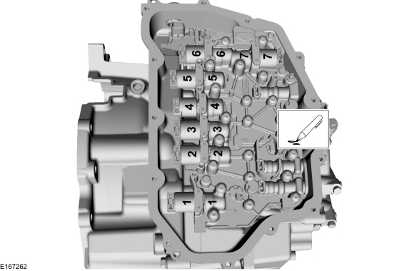
NOTICE: The solenoids are calibrated from the factory and are not all the same. Failure to install the solenoids in the ports they were originally in can result in damage to the transmission or a harsh shift.
NOTE: Note the position of the component before removal.
-
Line Pressure Control (LPC) solenoid 7G383 (high variable bleed)
-
Shift Solenoid C (SSC) 7G136 (low variable bleed)
-
TCC solenoid 7G136 (low variable bleed)
-
Shift Solenoid E (SSE) 7G484 (normally closed [OFF])
-
Shift Solenoid A (SSA) 7G136 (low variable bleed)
-
Shift Solenoid B (SSB) 7G383 (high variable bleed)
-
Shift Solenoid D (SSD) 7G383 (high variable bleed)
-
Line Pressure Control (LPC) solenoid 7G383 (high variable bleed)
 |
-
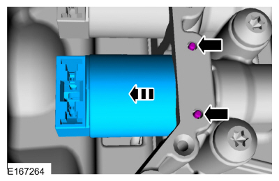
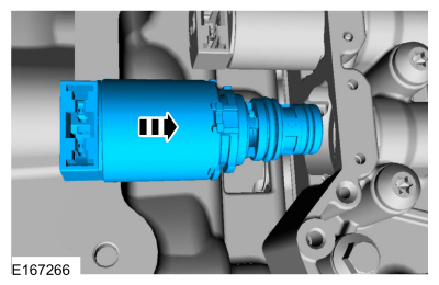
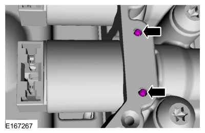
Remove the solenoid retaining pin(s) and the solenoid(s) from the solenoid body.
Use the General Equipment: Long Nose Pliers
 |
Installation
-
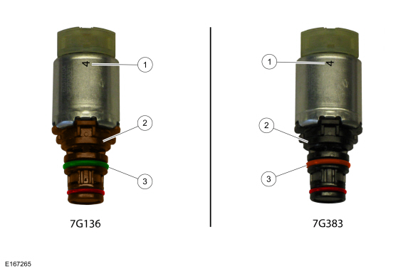
NOTE: Verify replacement component matches original component:
-
Number
-
Color
-
Color
-
Number
 |
-
NOTE: Make sure the component is installed in the position noted before removal.
Install the solenoid(s) in the solenoid body.
 |
-
Install the solenoid retaining pin(s).
 |
-
Install the transmission internal wiring harness frame.
Refer to: Transmission Internal Wiring Harness Frame (307-01A Automatic Transmission - 6-Speed Automatic Transmission – 6F35, Removal and Installation).
 Selector Shaft Seal. Removal and Installation
Special Tool(s) /
General Equipment
307-581Manual lever seal installerTKIT-2006UF-FLMTKIT-2006UF-ROW
Flat Headed Screw Driver
Removal
Remove the TR sensor...
 Solenoid Body. Removal and Installation
Removal
To remove the solenoid body.
Refer to: Main Control Valve Body (307-01A Automatic Transmission - 6-Speed Automatic Transmission – 6F35, Removal and Installation)...
Other information:
Ford Fusion 2013–2020 Service Manual: Parking Aid - Component Location. Description and Operation
Component Location - Active Park Assist Item Description 1 Front active park assist sensors 2 Active park assist switch 3 Rear active park assist sensors 4 PAM (integral to the BCM) ..
Ford Fusion 2013–2020 Owners Manual: Lane Keeping System (IF EQUIPPED)
WARNING: You are responsible for controlling your vehicle at all times. The system is designed to be an aid and does not relieve you of your responsibility to drive with due care and attention. Failure to follow this instruction could result in the loss of control of your vehicle, personal injury or death. WARNING: Always drive with due care and attention when using and operating the cont..
Categories
- Manuals Home
- 2nd Generation Ford Fusion Owners Manual
- 2nd Generation Ford Fusion Service Manual
- Front Controls Interface Module (FCIM). Removal and Installation
- Transmission - 1.5L EcoBoost (118kW/160PS) – I4. Removal and Installation
- Electronic Parking Brake (EPB) Service Mode Activation and Deactivation. General Procedures
- New on site
- Most important about car
Child Safety Locks
When these locks are set, the rear doors cannot be opened from the inside.

Copyright © 2026 www.fofusion2.com