Ford Fusion: Maintenance / Adjusting the Headlamps
Ford Fusion 2013–2020 Owners Manual / Maintenance / Adjusting the Headlamps
Vertical Aim Adjustment
The headlamps on your vehicle are properly aimed at the assembly plant. If your vehicle has been in an accident, the alignment of your headlamps should be checked by your authorized dealer.
Headlamp Aiming Target
- 8 feet (2.4 meters)
- Center height of lamp to ground
- 25 feet (7.6 meters)
- Horizontal reference line
Vertical Aim Adjustment Procedure
- Park the vehicle directly in front of a wall or screen on a level surface, approximately 25 ft (7.6 m) away.
- Measure the height of the headlamp
bulb center from the ground and mark
an 8 ft (2.4 m) horizontal reference line
on the vertical wall or screen at this
height.
Note: To see a clearer light pattern for adjusting, you may want to block the light from one headlamp while adjusting the other.
- Turn on the low beam headlamps to
illuminate the wall or screen and open
the hood.

- On the wall or screen you will observe
a flat zone of high intensity light
located at the top of the right hand
portion of the beam pattern. If the top
edge of the high intensity light zone is
not at the horizontal reference line, the
headlamp will need to be adjusted.
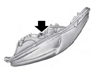
- Locate the vertical adjuster on each headlamp. Using a Phillips #2 screwdriver, turn the adjuster either clockwise or counterclockwise in order to adjust the vertical aim of the headlamp. The horizontal edge of the brighter light should touch the horizontal reference line.
- Close the hood and turn off the lamps.
Horizontal Aim Adjustment
Horizontal aim is not required for this vehicle and is not adjustable.
 Checking the Wiper Blades. Changing the Wiper Blades
Checking the Wiper Blades
Run the tip of your fingers over the edge of
the blade to check for roughness.
Clean the wiper blades with washer fluid
or water applied with a soft sponge or
cloth...
 Removing a Headlamp
Note: To remove push pins, use a
flat-bladed screwdriver to pull up the center
release pin.
Make sure the headlamp control is in
the off position and open the hood...
Other information:
Ford Fusion 2013–2020 Service Manual: External Controls. Diagnosis and Testing
Inspection and Verification Verify the customer concern. Visually inspect for obvious signs of mechanical or electrical damage. If an obvious cause for an observed or reported concern is found, correct the cause (if possible) before proceeding to the next step...
Ford Fusion 2013–2020 Service Manual: Cowl Panel. Removal and Installation
Special Tool(s) / General Equipment Resistance Spotwelding Equipment MIG/MAG Welding Equipment Spot Weld Drill Bit Locking Pliers Materials Name Specification Seam SealerTA-2-B, 3M™ 08308, LORD Fusor® 803DTM - Removal NOTICE: Battery electric vehicle (BEV), hybrid electric vehicle (HEV) and plug-in hybrid electric vehicle (PHEV) contain a hig..
Categories
- Manuals Home
- 2nd Generation Ford Fusion Owners Manual
- 2nd Generation Ford Fusion Service Manual
- Pre-Collision Assist (IF EQUIPPED)
- Cylinder Head. Removal and Installation
- Automatic Transmission Fluid Check - 1.5L EcoBoost™/2.0L EcoBoost™/2.5L. Automatic Transmission Fluid Check - 2.7L EcoBoost™
- New on site
- Most important about car
Manual Climate Control

Note: Depending on your vehicle option package, the controls may look different from what you see here.
Copyright © 2026 www.fofusion2.com