Ford Fusion: Handles, Locks, Latches and Entry Systems / Locks, Latches and Entry Systems. Diagnosis and Testing
DTC Charts
Diagnostics in this manual assume a certain skill level and knowledge of Ford-specific diagnostic practices.
REFER to: Diagnostic Methods (100-00 General Information, Description and Operation).
BCM DTC Chart
| DTC | Description | Action |
|---|---|---|
| B10AB:00 | Remote Keyless Entry Synchronization: No Sub Type Information | GO to Pinpoint Test U |
| B10C7:01 | Interior Trunk Antenna: General Electrical Failure | GO to Pinpoint Test Z |
| B11C6:01 | Passenger Door External Antenna: General Electrical Failure | GO to Pinpoint Test Y |
| B11CA:01 | Driver Door External Antenna: General Electrical Failure | GO to Pinpoint Test Y |
| B1218:00 | Transmitter Identification Code: No Sub Type Information | GO to Pinpoint Test U |
| B1219:11 | Interior Boot/Trunk Release Switch: Circuit Short To Ground | GO to Pinpoint Test N |
| B121A:11 | Keypad Illumination Output: Circuit Short To Ground | GO to Pinpoint Test S |
| B121A:15 | Keypad Illumination Output: Circuit Short To Battery or Open |
|
| B121B:01 | Keypad Input Switch: General Electrical Failure | GO to Pinpoint Test R |
| B126A:01 | Drivers Door Interior Lock Switch: General Electrical Failure |
|
| B12EE:11 | Liftgate/Tailgate/Trunk Release: Circuit Short To Ground | GO to Pinpoint Test N |
| B12EE:15 | Liftgate/Tailgate/Trunk Release: Circuit Short To Battery or Open | GO to Pinpoint Test N |
| B1381:11 | Left Front Door Handle Proximity Sensor: Circuit Short To Ground | GO to Pinpoint Test Y |
| B1381:15 | Left Front Door Handle Proximity Sensor: Circuit Short To Battery or Open | GO to Pinpoint Test Y |
| B1381:29 | Left Front Door Handle Proximity Sensor: Signal Invalid | GO to Pinpoint Test Y |
| B1382:11 | Right Front Door Handle Proximity Sensor: Circuit Short To Ground | GO to Pinpoint Test Y |
| B1382:15 | Right Front Door Handle Proximity Sensor: Circuit Short To Battery or Open | GO to Pinpoint Test Y |
| B1382:29 | Right Front Door Handle Proximity Sensor: Signal Invalid | GO to Pinpoint Test Y |
| B1383:11 | Left Rear Door Handle Proximity Sensor: Circuit Short To Ground | GO to Pinpoint Test Y |
| B1383:15 | Left Rear Door Handle Proximity Sensor: Circuit Short To Battery or Open | GO to Pinpoint Test Y |
| B1383:29 | Left Rear Door Handle Proximity Sensor: Signal Invalid | GO to Pinpoint Test Y |
| B1384:11 | Right Rear Door Handle Proximity Sensor: Circuit Short To Ground | GO to Pinpoint Test Y |
| B1384:15 | Right Rear Door Handle Proximity Sensor: Circuit Short To Battery or Open | GO to Pinpoint Test Y |
| B1384:29 | Right Rear Door Handle Proximity Sensor: Signal Invalid | GO to Pinpoint Test Y |
| B1490:11 | Lock Indicator LED Status Output: Circuit Short To Ground | GO to Pinpoint Test L |
| B1490:15 | Lock Indicator LED Status Output: Circuit Short To Battery or Open |
|
| C1017:11 | Boot/Trunk Primary Switch: Circuit Short To Ground | GO to Pinpoint Test N |
| P0830:11 | Clutch Pedal Switch "A" Circuit: Circuit Short To Ground | GO to Pinpoint Test O |
| U0258:87 | Lost Communication With Radio Transceiver: Missing Message | GO to Pinpoint Test AA |
| All other Diagnostic Trouble Codes (DTCs) | - |
REFER to: Body Control Module (BCM) (419-10 Multifunction Electronic Modules, Diagnosis and Testing). |
Diagnostics in this manual assume a certain skill level and knowledge of Ford-specific diagnostic practices.
REFER to: Diagnostic Methods (100-00 General Information, Description and Operation).
RTM DTC Chart
| DTC | Description | Action |
|---|---|---|
| U1A00:00 | Private Communication Network: No Sub Type Information | GO to Pinpoint Test AA |
| All other Diagnostic Trouble Codes (DTCs) | - |
REFER to: Tire Pressure Monitoring System (TPMS) (204-04B Tire Pressure Monitoring System (TPMS), Diagnosis and Testing). |
Diagnostics in this manual assume a certain skill level and knowledge of Ford-specific diagnostic practices.
REFER to: Diagnostic Methods (100-00 General Information, Description and Operation).
PCM DTC Chart
| DTC | Description | Action |
|---|---|---|
| P04B5 | Fuel Fill Door Stuck Open | GO to Pinpoint Test AB |
| P04B9 | Fuel Fill Door Position Sensor/Switch Circuit Low | GO to Pinpoint Test AB |
| P04BA | Fuel Fill Door Position Sensor/Switch Circuit High | GO to Pinpoint Test AB |
| P04C1 | Fuel Fill Door Unlock Control Circuit Low | GO to Pinpoint Test P |
| P04C2 | Fuel Fill Door Unlock Control Circuit High | GO to Pinpoint Test O |
| P04C9 | Fuel Fill Door Open Request Sensor/Switch Performance/Stuck Off | GO to Pinpoint Test O |
| P04CA | Fuel Fill Door Open Request Sensor/Switch Stuck Low | GO to Pinpoint Test O |
| P04CD | Fuel Fill Door Open Request Sensor/Switch Stuck On | GO to Pinpoint Test O |
| All other Diagnostic Trouble Codes (DTCs) | - | REFER to the PCM DTC Chart in the appropriate 303-14 section. |
Diagnostics in this manual assume a certain skill level and knowledge of Ford-specific diagnostic practices.
REFER to: Diagnostic Methods (100-00 General Information, Description and Operation).
DDM DTC Chart
| DTC | Description | Action |
|---|---|---|
| B1087:83 | LIN Bus "A": Value Of Signal Protection Calculation Incorrect | GO to Pinpoint Test AC |
| B1087:87 | LIN Bus "A": Missing Message | GO to Pinpoint Test AC |
| B1088:83 | LIN Bus "B": Value of Signal Protection Calculation Incorrect |
REFER to: Glass, Frames and Mechanisms (501-11 Glass, Frames and Mechanisms, Diagnosis and Testing). |
| B1088:87 | LIN Bus "B": Missing Message |
REFER to: Glass, Frames and Mechanisms (501-11 Glass, Frames and Mechanisms, Diagnosis and Testing). |
| B108F:23 | Cabin Lock/Unlock Switch: Signal Stuck Low | GO to Pinpoint Test J |
| B1142:29 | Ignition Status 1: Signal Invalid | GO to Pinpoint Test AD |
| B1163:11 | Left Mirror Heater Output: Circuit Short To Ground |
REFER to: Rear View Mirrors (501-09 Rear View Mirrors, Diagnosis and Testing). |
| B1163:15 | Left Mirror Heater Output: Circuit Short To Battery or Open |
REFER to: Rear View Mirrors (501-09 Rear View Mirrors, Diagnosis and Testing). |
| B1165:11 | Left Front Puddle Lamp Output: Circuit Short To Ground |
REFER to: Interior Lighting (417-02 Interior Lighting, Diagnosis and Testing). |
| B1165:15 | Left Front Puddle Lamp Output: Circuit Short To Battery or Open |
REFER to: Interior Lighting (417-02 Interior Lighting, Diagnosis and Testing). |
| B117C:07 | Rear Power Window Up: Mechanical Failure |
REFER to: Glass, Frames and Mechanisms (501-11 Glass, Frames and Mechanisms, Diagnosis and Testing). |
| B117C:16 | Rear Power Window Up: Circuit Voltage Below Threshold |
REFER to: Glass, Frames and Mechanisms (501-11 Glass, Frames and Mechanisms, Diagnosis and Testing). |
| B117C:4B | Rear Power Window Up: Over Temperature |
REFER to: Glass, Frames and Mechanisms (501-11 Glass, Frames and Mechanisms, Diagnosis and Testing). |
| B117C:92 | Rear Power Window Up: Performance or Incorrect Operation |
INITIALIZE the LH rear door window regulator motor. REFER to: Power Door Window Initialization (501-11 Glass, Frames and Mechanisms, General Procedures). |
| B117E:07 | Front Power Window Up: Mechanical Failure |
REFER to: Glass, Frames and Mechanisms (501-11 Glass, Frames and Mechanisms, Diagnosis and Testing). |
| B117E:16 | Front Power Window Up: Circuit Voltage Below Threshold |
REFER to: Glass, Frames and Mechanisms (501-11 Glass, Frames and Mechanisms, Diagnosis and Testing). |
| B117E:4B | Front Power Window Up: Over Temperature |
REFER to: Glass, Frames and Mechanisms (501-11 Glass, Frames and Mechanisms, Diagnosis and Testing). |
| B117E:92 | Front Power Window Up: Performance or Incorrect Operation |
REFER to: Glass, Frames and Mechanisms (501-11 Glass, Frames and Mechanisms, Diagnosis and Testing). |
| B1189:29 | Front Window Position Sensor: Signal Invalid |
REFER to: Glass, Frames and Mechanisms (501-11 Glass, Frames and Mechanisms, Diagnosis and Testing). |
| B118A:29 | Rear Window Position Sensor: Signal Invalid |
REFER to: Glass, Frames and Mechanisms (501-11 Glass, Frames and Mechanisms, Diagnosis and Testing). |
| B118C:11 | Left Blind Spot Warning Indicator: Circuit Short To Ground |
REFER to: Blind Spot Information System (419-04 Side and Rear Vision, Diagnosis and Testing). |
| B118C:15 | Left Blind Spot Warning Indicator: Circuit Short To Battery or Open |
REFER to: Blind Spot Information System (419-04 Side and Rear Vision, Diagnosis and Testing). |
| B11DA:23 | Driver Door Key Cylinder Switch: Signal Stuck Low |
REFER to: Perimeter Anti-Theft Alarm (419-01A Perimeter Anti-Theft Alarm, Diagnosis and Testing). |
| B11F6:11 | Driver Folding Mirror Motor: Circuit Short To Ground |
REFER to: Rear View Mirrors (501-09 Rear View Mirrors, Diagnosis and Testing). |
| B11F6:15 | Driver Folding Mirror Motor: Circuit Short To Battery or Open |
REFER to: Rear View Mirrors (501-09 Rear View Mirrors, Diagnosis and Testing). |
| B12BA:11 | Lock Status LED - Front: Circuit Short To Ground | GO to Pinpoint Test L |
| B12C5:71 | Front Window Lifter Motor Up Relay: Actuator Stuck |
REFER to: Glass, Frames and Mechanisms (501-11 Glass, Frames and Mechanisms, Diagnosis and Testing). |
| B12C6:71 | Rear Window Lifter Motor Up Relay: Actuator Stuck |
REFER to: Glass, Frames and Mechanisms (501-11 Glass, Frames and Mechanisms, Diagnosis and Testing). |
| B12C7:71 | Front Window Lifter Motor Down Relay: Actuator Stuck |
REFER to: Glass, Frames and Mechanisms (501-11 Glass, Frames and Mechanisms, Diagnosis and Testing). |
| B12C8:71 | Rear Window Lifter Motor Down Relay: Actuator Stuck |
REFER to: Glass, Frames and Mechanisms (501-11 Glass, Frames and Mechanisms, Diagnosis and Testing). |
| B12E9:23 | Rear Window Local Up/Down Switch: Signal Stuck Low |
REFER to: Glass, Frames and Mechanisms (501-11 Glass, Frames and Mechanisms, Diagnosis and Testing). |
| B12E9:24 | Rear Window Local Up/Down Switch: Signal Stuck High |
REFER to: Glass, Frames and Mechanisms (501-11 Glass, Frames and Mechanisms, Diagnosis and Testing). |
| B12FF:11 | Rear Door Switch Illumination: Circuit Short To Ground |
REFER to: Instrument Panel and Interior Switches Illumination (413-00 Instrument Panel and Interior Switches Illumination, Diagnosis and Testing). |
| B12FF:15 | Rear Door Switch Illumination: Circuit Short To Battery or Open |
REFER to: Instrument Panel and Interior Switches Illumination (413-00 Instrument Panel and Interior Switches Illumination, Diagnosis and Testing). |
| B13F0:4B | Left Rear Power Window Motor: Over Temperature |
REFER to: Glass, Frames and Mechanisms (501-11 Glass, Frames and Mechanisms, Diagnosis and Testing). |
| B13F1:4B | Driver Power Window Motor: Over Temperature |
REFER to: Glass, Frames and Mechanisms (501-11 Glass, Frames and Mechanisms, Diagnosis and Testing). |
| B1C03:23 | Memory #1 Switch: Signal Stuck Low |
REFER to: Front Seats (501-10A Front Seats, Diagnosis and Testing). |
| B1C04:23 | Memory #2 Switch: Signal Stuck Low |
REFER to: Front Seats (501-10A Front Seats, Diagnosis and Testing). |
| B1C06:11 | Driver Up/Down And Common Mirror Motor: Circuit Short To Ground |
REFER to: Rear View Mirrors (501-09 Rear View Mirrors, Diagnosis and Testing). |
| B1C06:15 | Driver Up/Down And Common Mirror Motor Circuit: Short To Battery or Open |
REFER to: Rear View Mirrors (501-09 Rear View Mirrors, Diagnosis and Testing). |
| B1C09:11 | Driver Left/Right Mirror Motor: Circuit Short To Ground |
REFER to: Rear View Mirrors (501-09 Rear View Mirrors, Diagnosis and Testing). |
| B1C09:15 | Driver Left/Right Mirror Motor: Circuit Short To Battery or Open |
REFER to: Rear View Mirrors (501-09 Rear View Mirrors, Diagnosis and Testing). |
| B1C10:11 | Driver Up/Down Mirror Motor: Circuit Short To Ground |
REFER to: Rear View Mirrors (501-09 Rear View Mirrors, Diagnosis and Testing). |
| B1C10:15 | Driver Up/Down Mirror Motor: Circuit Short To Battery or Open |
REFER to: Rear View Mirrors (501-09 Rear View Mirrors, Diagnosis and Testing). |
| B1C13:11 | Driver Up/Down Mirror Motor Feedback: Circuit Short To Ground |
REFER to: Rear View Mirrors (501-09 Rear View Mirrors, Diagnosis and Testing). |
| B1C13:15 | Driver Up/Down Mirror Motor Feedback: Circuit Short To Battery or Open |
REFER to: Rear View Mirrors (501-09 Rear View Mirrors, Diagnosis and Testing). |
| B1C14:11 | Driver Left/Right Mirror Motor Feedback: Circuit Short To Ground |
REFER to: Rear View Mirrors (501-09 Rear View Mirrors, Diagnosis and Testing). |
| B1C14:15 | Driver Left/Right Mirror Motor Feedback: Circuit Short To Battery or Open |
REFER to: Rear View Mirrors (501-09 Rear View Mirrors, Diagnosis and Testing). |
| B1D06:11 | Left Turn Indicator: Circuit Short To Ground |
REFER to: Turn Signal and Hazard Lamps (417-01 Exterior Lighting, Diagnosis and Testing). |
| B1D06:15 | Left Turn Indicator: Circuit Short To Battery or Open |
REFER to: Turn Signal and Hazard Lamps (417-01 Exterior Lighting, Diagnosis and Testing). |
| C1B14:11 | Sensor Supply Voltage A: Circuit Short To Ground |
REFER to: Glass, Frames and Mechanisms (501-11 Glass, Frames and Mechanisms, Diagnosis and Testing). |
| C1B14:15 | Sensor Supply Voltage A: Circuit Short To Battery or Open |
REFER to: Glass, Frames and Mechanisms (501-11 Glass, Frames and Mechanisms, Diagnosis and Testing). |
| C1B15:11 | Sensor Supply Voltage B: Circuit Short To Ground |
REFER to: Rear View Mirrors (501-09 Rear View Mirrors, Diagnosis and Testing). |
| C1B15:15 | Sensor Supply Voltage B: Circuit Short To Battery or Open |
REFER to: Rear View Mirrors (501-09 Rear View Mirrors, Diagnosis and Testing). |
| U0010:00 | Medium Speed CAN Communication Bus: No Sub Type Information | The module was unable to communicate on the network at a point in time. The fault is not currently present (the module had to communicate with the scan tool to report this DTC). VERIFY the continuity of the connectors and wiring. Refer to Wiring Diagrams Cell 14 Module Communications Network for schematic and connector information. |
| U0140:00 | Lost Communication With Body Control Module: No Sub Type Information | GO to Pinpoint Test AE |
| U0164:00 | Lost Communication With HVAC Control Module: No Sub Type Information | GO to Pinpoint Test AF |
| U0208:00 | Lost Communication With "Seat Control Module A": No Sub Type Information | GO to Pinpoint Test AG |
| U0232:00 | Lost Communication With Side Obstacle Detection Control Module - Left: No Sub Type Information | GO to Pinpoint Test AH |
| U0294:00 | Lost Communication With Powertrain Control Monitor Module: No Sub Type Information | GO to Pinpoint Test AJ |
| U0300:00 | Internal Control Module Software Incompatibility: No Sub Type Information |
CLEAR the Diagnostic Trouble Codes (DTCs) and REPEAT the self-test. If the DTC is retrieved again, INSTALL a new DDM. REFER to: Driver Door Module (DDM) (419-10 Multifunction Electronic Modules, Removal and Installation). |
| U0300:4A | Internal Control Module Software Incompatibility: Incorrect Component Installed |
CARRY OUT the PMI using as-built data. CLEAR the Diagnostic Trouble Codes (DTCs) and REPEAT the self-test. If the DTC returns, INSTALL a new DDM. REFER to: Driver Door Module (DDM) (419-10 Multifunction Electronic Modules, Removal and Installation). |
| U0422:00 | Invalid Data Received From Body Control Module: No Sub Type Information |
RETRIEVE and REPAIR all non-network Diagnostic Trouble Codes (DTCs) from the BCM. REFER to: Body Control Module (BCM) (419-10 Multifunction Electronic Modules, Diagnosis and Testing). |
| U0509:00 | Invalid Data Received From "Seat Control Module A": No Sub Type Information |
RETRIEVE and REPAIR all non-network Diagnostic Trouble Codes (DTCs) from the DSM. REFER to: Front Seats (501-10A Front Seats, Diagnosis and Testing). |
| U2010:11 | Switch Illumination: Circuit Short To Ground |
REFER to: Instrument Panel and Interior Switches Illumination (413-00 Instrument Panel and Interior Switches Illumination, Diagnosis and Testing). |
| U2013:24 | Switch Pack: Signal Stuck High |
REFER to: Glass, Frames and Mechanisms (501-11 Glass, Frames and Mechanisms, Diagnosis and Testing). |
| U2014:00 | Control Module Hardware: No Sub Type Information |
INSTALL a new DDM. REFER to: Driver Door Module (DDM) (419-10 Multifunction Electronic Modules, Removal and Installation). |
| U2100:00 | Initial Configuration Not Complete: No Sub Type Information |
CARRY OUT the PMI using as-built data. CLEAR the Diagnostic Trouble Codes (DTCs) and REPEAT the self-test. If the DTC returns, INSTALL a new DDM. REFER to: Driver Door Module (DDM) (419-10 Multifunction Electronic Modules, Removal and Installation). |
| U2200:00 | Control Module Configuration Memory Corrupt: No Sub Type Information |
CLEAR the Diagnostic Trouble Codes (DTCs) and REPEAT the self-test. If the DTC returns, INSTALL a new DDM. REFER to: Driver Door Module (DDM) (419-10 Multifunction Electronic Modules, Removal and Installation). |
| U3000:04 | Control Module: System Internal Failure |
INSTALL a new DDM. REFER to: Driver Door Module (DDM) (419-10 Multifunction Electronic Modules, Removal and Installation). |
| U3000:49 | Control Module: Internal Electronic Failure |
CLEAR the Diagnostic Trouble Codes (DTCs) and REPEAT the self-test. If the DTC returns, INSTALL a new DDM. REFER to: Driver Door Module (DDM) (419-10 Multifunction Electronic Modules, Removal and Installation). |
Diagnostics in this manual assume a certain skill level and knowledge of Ford-specific diagnostic practices.
REFER to: Diagnostic Methods (100-00 General Information, Description and Operation).
PDM DTC Chart
| DTC | Description | Action |
|---|---|---|
| B1087:83 | LIN Bus "A": Value Of Signal Protection Calculation Incorrect | GO to Pinpoint Test AC |
| B1087:87 | LIN Bus "A": Missing Message | GO to Pinpoint Test AC |
| B108F:23 | Cabin Lock/Unlock Switch: Signal Stuck Low | GO to Pinpoint Test J |
| B1142:29 | Ignition Status 1: Signal Invalid | GO to Pinpoint Test AD |
| B1164:11 | Right Mirror Heater Output: Circuit Short To Ground |
REFER to: Rear View Mirrors (501-09 Rear View Mirrors, Diagnosis and Testing). |
| B1164:15 | Right Mirror Heater Output: Circuit Short To Battery or Open |
REFER to: Rear View Mirrors (501-09 Rear View Mirrors, Diagnosis and Testing). |
| B1166:11 | Right Front Puddle Lamp Output: Circuit Short To Ground |
REFER to: Interior Lighting (417-02 Interior Lighting, Diagnosis and Testing). |
| B1166:15 | Right Front Puddle Lamp Output: Circuit Short To Battery or Open |
REFER to: Interior Lighting (417-02 Interior Lighting, Diagnosis and Testing). |
| B117C:07 | Rear Power Window Up: Mechanical Failure |
REFER to: Glass, Frames and Mechanisms (501-11 Glass, Frames and Mechanisms, Diagnosis and Testing). |
| B117C:16 | Rear Power Window Up: Circuit Voltage Below Threshold |
REFER to: Glass, Frames and Mechanisms (501-11 Glass, Frames and Mechanisms, Diagnosis and Testing). |
| B117C:4B | Rear Power Window Up: Over Temperature |
REFER to: Glass, Frames and Mechanisms (501-11 Glass, Frames and Mechanisms, Diagnosis and Testing). |
| B117C:92 | Rear Power Window Up: Performance or Incorrect Operation |
INITIALIZE the LH rear door window regulator motor. REFER to: Power Door Window Initialization (501-11 Glass, Frames and Mechanisms, General Procedures). |
| B117E:07 | Front Power Window Up: Mechanical Failure |
REFER to: Glass, Frames and Mechanisms (501-11 Glass, Frames and Mechanisms, Diagnosis and Testing). |
| B117E:16 | Front Power Window Up: Circuit Voltage Below Threshold |
REFER to: Glass, Frames and Mechanisms (501-11 Glass, Frames and Mechanisms, Diagnosis and Testing). |
| B117E:4B | Front Power Window Up: Over Temperature |
REFER to: Glass, Frames and Mechanisms (501-11 Glass, Frames and Mechanisms, Diagnosis and Testing). |
| B117E:92 | Front Power Window Up: Performance or Incorrect Operation |
REFER to: Glass, Frames and Mechanisms (501-11 Glass, Frames and Mechanisms, Diagnosis and Testing). |
| B1189:29 | Front Window Position Sensor: Signal Invalid |
REFER to: Glass, Frames and Mechanisms (501-11 Glass, Frames and Mechanisms, Diagnosis and Testing). |
| B118A:29 | Rear Window Position Sensor: Signal Invalid |
REFER to: Glass, Frames and Mechanisms (501-11 Glass, Frames and Mechanisms, Diagnosis and Testing). |
| B118D:11 | Right Blind Spot Warning Indicator: Circuit Short To Ground |
REFER to: Blind Spot Information System (419-04 Side and Rear Vision, Diagnosis and Testing). |
| B118D:15 | Right Blind Spot Warning Indicator: Circuit Short To Battery or Open |
REFER to: Blind Spot Information System (419-04 Side and Rear Vision, Diagnosis and Testing). |
| B11F7:11 | Passenger Folding Mirror Motor: Circuit Short To Ground |
REFER to: Rear View Mirrors (501-09 Rear View Mirrors, Diagnosis and Testing). |
| B11F7:15 | Passenger Folding Mirror Motor: Circuit Short To Battery or Open |
REFER to: Rear View Mirrors (501-09 Rear View Mirrors, Diagnosis and Testing). |
| B12BA:11 | Lock Status LED - Front: Circuit Short To Ground | GO to Pinpoint Test L |
| B12C5:71 | Front Window Lifter Motor Up Relay: Actuator Stuck |
REFER to: Glass, Frames and Mechanisms (501-11 Glass, Frames and Mechanisms, Diagnosis and Testing). |
| B12C6:71 | Rear Window Lifter Motor Up Relay: Actuator Stuck |
REFER to: Glass, Frames and Mechanisms (501-11 Glass, Frames and Mechanisms, Diagnosis and Testing). |
| B12C7:71 | Front Window Lifter Motor Down Relay: Actuator Stuck |
REFER to: Glass, Frames and Mechanisms (501-11 Glass, Frames and Mechanisms, Diagnosis and Testing). |
| B12C8:71 | Rear Window Lifter Motor Down Relay: Actuator Stuck |
REFER to: Glass, Frames and Mechanisms (501-11 Glass, Frames and Mechanisms, Diagnosis and Testing). |
| B12E9:23 | Rear Window Local Up/Down Switch: Signal Stuck Low |
REFER to: Glass, Frames and Mechanisms (501-11 Glass, Frames and Mechanisms, Diagnosis and Testing). |
| B12E9:24 | Rear Window Local Up/Down Switch: Signal Stuck High |
REFER to: Glass, Frames and Mechanisms (501-11 Glass, Frames and Mechanisms, Diagnosis and Testing). |
| B12FF:11 | Rear Door Switch Illumination: Circuit Short To Ground |
REFER to: Instrument Panel and Interior Switches Illumination (413-00 Instrument Panel and Interior Switches Illumination, Diagnosis and Testing). |
| B12FF:15 | Rear Door Switch Illumination: Circuit Short To Battery or Open |
REFER to: Instrument Panel and Interior Switches Illumination (413-00 Instrument Panel and Interior Switches Illumination, Diagnosis and Testing). |
| B13EF:4B | Right Rear Power Window Motor: Over Temperature |
REFER to: Glass, Frames and Mechanisms (501-11 Glass, Frames and Mechanisms, Diagnosis and Testing). |
| B13F2:4B | Passenger Power Window Motor: Over Temperature |
REFER to: Glass, Frames and Mechanisms (501-11 Glass, Frames and Mechanisms, Diagnosis and Testing). |
| B13E5:23 | Passenger Power Window Switch Up: Signal Stuck Low |
REFER to: Glass, Frames and Mechanisms (501-11 Glass, Frames and Mechanisms, Diagnosis and Testing). |
| B13E6:23 | Passenger Power Window Switch Down: Signal Stuck Low |
REFER to: Glass, Frames and Mechanisms (501-11 Glass, Frames and Mechanisms, Diagnosis and Testing). |
| B1C08:11 | Passenger Left/Right and Common Mirror Motor: Circuit Short To Ground |
REFER to: Rear View Mirrors (501-09 Rear View Mirrors, Diagnosis and Testing). |
| B1C08:15 | Passenger Left/Right and Common Mirror Motor: Circuit Short To Battery or Open |
REFER to: Rear View Mirrors (501-09 Rear View Mirrors, Diagnosis and Testing). |
| B1C11:11 | Passenger Left/Right Mirror Motor: Circuit Short To Ground |
REFER to: Rear View Mirrors (501-09 Rear View Mirrors, Diagnosis and Testing). |
| B1C11:15 | Passenger Left/Right Mirror Motor: Circuit Short To Battery or Open |
REFER to: Rear View Mirrors (501-09 Rear View Mirrors, Diagnosis and Testing). |
| B1C12:11 | Passenger Up/Down Mirror Motor: Circuit Short To Ground |
REFER to: Rear View Mirrors (501-09 Rear View Mirrors, Diagnosis and Testing). |
| B1C12:15 | Passenger Up/Down Mirror Motor: Circuit Short To Battery or Open |
REFER to: Rear View Mirrors (501-09 Rear View Mirrors, Diagnosis and Testing). |
| B1C15:11 | Passenger Up/Down Mirror Motor Feedback: Circuit Short To Ground |
REFER to: Rear View Mirrors (501-09 Rear View Mirrors, Diagnosis and Testing). |
| B1C15:15 | Passenger Up/Down Mirror Motor Feedback: Circuit Short To Battery or Open |
REFER to: Rear View Mirrors (501-09 Rear View Mirrors, Diagnosis and Testing). |
| B1C16:11 | Passenger Left/Right Mirror Motor Feedback: Circuit Short To Ground |
REFER to: Rear View Mirrors (501-09 Rear View Mirrors, Diagnosis and Testing). |
| B1C16:15 | Passenger Left/Right Mirror Motor Feedback: Circuit Short To Battery or Open |
REFER to: Rear View Mirrors (501-09 Rear View Mirrors, Diagnosis and Testing). |
| B1D07:11 | Right Turn Indicator: Circuit Short To Ground |
REFER to: Turn Signal and Hazard Lamps (417-01 Exterior Lighting, Diagnosis and Testing). |
| B1D07:15 | Right Turn Indicator: Circuit Short To Battery or Open |
REFER to: Turn Signal and Hazard Lamps (417-01 Exterior Lighting, Diagnosis and Testing). |
| C1B14:11 | Sensor Supply Voltage A: Circuit Short To Ground |
REFER to: Glass, Frames and Mechanisms (501-11 Glass, Frames and Mechanisms, Diagnosis and Testing). |
| C1B14:15 | Sensor Supply Voltage A: Circuit Short To Battery or Open |
REFER to: Glass, Frames and Mechanisms (501-11 Glass, Frames and Mechanisms, Diagnosis and Testing). |
| C1B15:11 | Sensor Supply Voltage B: Circuit Short To Ground |
REFER to: Rear View Mirrors (501-09 Rear View Mirrors, Diagnosis and Testing). |
| C1B15:15 | Sensor Supply Voltage B: Circuit Short To Battery or Open |
REFER to: Rear View Mirrors (501-09 Rear View Mirrors, Diagnosis and Testing). |
| U0010:00 | Medium Speed CAN Communication Bus: No Sub Type Information | The module was unable to communicate on the network at a point in time. The fault is not currently present (the module had to communicate with the scan tool to report this DTC). VERIFY the continuity of the connectors and wiring. Refer to Wiring Diagrams Cell 14 Module Communications Network for schematic and connector information. |
| U0140:00 | Lost Communication With Body Control Module: No Sub Type Information | GO to Pinpoint Test AE |
| U0164:00 | Lost Communication With HVAC Control Module: No Sub Type Information | GO to Pinpoint Test AF |
| U0208:00 | Lost Communication With "Seat Control Module A": No Sub Type Information | GO to Pinpoint Test AG |
| U0233:00 | Lost Communication With Side Obstacle Detection Control Module - Right: No Sub Type Information | GO to Pinpoint Test AI |
| U0294:00 | Lost Communication With Powertrain Control Monitor Module: No Sub Type Information | GO to Pinpoint Test AJ |
| U0300:00 | Internal Control Module Software Incompatibility: No Sub Type Information |
CLEAR the Diagnostic Trouble Codes (DTCs) and REPEAT the self-test. If the DTC is retrieved again, INSTALL a new PDM. REFER to: Passenger Door Module (PDM) (419-10 Multifunction Electronic Modules, Removal and Installation). |
| U0300:4A | Internal Control Module Software Incompatibility: Incorrect Component Installed |
CARRY OUT the PMI using as-built data. CLEAR the Diagnostic Trouble Codes (DTCs) and REPEAT the self-test. If the DTC returns, INSTALL a new PDM. REFER to: Passenger Door Module (PDM) (419-10 Multifunction Electronic Modules, Removal and Installation). |
| U0422:00 | Invalid Data Received From Body Control Module: No Sub Type Information |
RETRIEVE and REPAIR all non-network Diagnostic Trouble Codes (DTCs) from the BCM. REFER to: Body Control Module (BCM) (419-10 Multifunction Electronic Modules, Diagnosis and Testing). |
| U0509:00 | Invalid Data Received From "Seat Control Module A": No Sub Type Information |
RETRIEVE and REPAIR all non-network Diagnostic Trouble Codes (DTCs) from the DSM. REFER to: Front Seats (501-10A Front Seats, Diagnosis and Testing). |
| U2002:24 | Switch: Signal Stuck High |
REFER to: Glass, Frames and Mechanisms (501-11 Glass, Frames and Mechanisms, Diagnosis and Testing). |
| U2010:00 | Switch Illumination: No Sub Type Information |
REFER to: Instrument Panel and Interior Switches Illumination (413-00 Instrument Panel and Interior Switches Illumination, Diagnosis and Testing). |
| U2010:11 | Switch Illumination: Circuit Short To Ground |
REFER to: Instrument Panel and Interior Switches Illumination (413-00 Instrument Panel and Interior Switches Illumination, Diagnosis and Testing). |
| U2014:00 | Control Module Hardware: No Sub Type Information |
INSTALL a new DDM. REFER to: Driver Door Module (DDM) (419-10 Multifunction Electronic Modules, Removal and Installation). |
| U2100:00 | Initial Configuration Not Complete: No Sub Type Information |
CARRY OUT the PMI using as-built data. CLEAR the Diagnostic Trouble Codes (DTCs) and REPEAT the self-test. If the DTC returns, INSTALL a new PDM. REFER to: Passenger Door Module (PDM) (419-10 Multifunction Electronic Modules, Removal and Installation). |
| U2200:00 | Control Module Configuration Memory Corrupt: No Sub Type Information |
CLEAR the Diagnostic Trouble Codes (DTCs) and REPEAT the self-test. If the DTC returns, INSTALL a new PDM. REFER to: Passenger Door Module (PDM) (419-10 Multifunction Electronic Modules, Removal and Installation). |
| U3000:04 | Control Module: System Internal Failure |
INSTALL a new DDM. REFER to: Driver Door Module (DDM) (419-10 Multifunction Electronic Modules, Removal and Installation). |
| U3000:49 | Control Module: Internal Electronic Failure |
CLEAR the Diagnostic Trouble Codes (DTCs) and REPEAT the self-test. If the DTC returns, INSTALL a new PDM. REFER to: Passenger Door Module (PDM) (419-10 Multifunction Electronic Modules, Removal and Installation). |
Diagnostics in this manual assume a certain skill level and knowledge of Ford-specific diagnostic practices.
REFER to: Diagnostic Methods (100-00 General Information, Description and Operation).
SOBDMC DTC Chart
| DTC | Description | Action |
|---|---|---|
| P1594 | Forced Engine Shutdown - Remote Start System Fault, No Unattended Vehicle Timeout | GO to Pinpoint Test AK |
| P1595 | Forced Engine Shutdown - Remote Start System Fault, Transmission Range Not In Park Position | GO to Pinpoint Test AK |
| All other Diagnostic Trouble Codes (DTCs) | - | Refer to Powertrain Control/Emissions Diagnosis (PC/ED) manual. |
Symptom Charts
Symptom Chart: Handles, Locks, Latches and Entry Systems - Mechanical
Diagnostics in this manual assume a certain skill level and knowledge of Ford-specific diagnostic practices.
REFER to: Diagnostic Methods (100-00 General Information, Description and Operation).
| Condition | Possible Causes | Actions |
|---|---|---|
| Hard to open or close a door from either door handle |
|
|
| A door is difficult or does not open from the exterior door handle |
|
|
| A door is difficult or does not open from the interior door handle |
|
|
| The exterior door release handle sticks |
|
|
| The interior door release handle sticks |
|
|
| Squeak-rattle-chucking noise from door |
|
|
| The manual door lock cylinder is inoperative |
|
|
Symptom Chart: Handles, Locks, Latches and Entry Systems - Electrical
Diagnostics in this manual assume a certain skill level and knowledge of Ford-specific diagnostic practices.
REFER to: Diagnostic Methods (100-00 General Information, Description and Operation).
| Condition | Possible Causes | Actions |
|---|---|---|
| All door locks are inoperative |
|
|
| A single or more than one door lock is inoperative |
|
|
| The door locks operate only one way |
|
|
| All door locks are inoperative from one door lock control switch |
|
|
| A door lock indicator is inoperative |
|
|
| A door lock indicator is always on |
|
|
| The luggage compartment lid latch releases when not requested |
|
|
| The luggage compartment lid latch release is inoperative |
|
|
| The luggage compartment lid latch does not latch |
|
|
| The fuel filler door release is inoperative (hybrid vehicles) |
|
|
| The fuel filler door does not latch (hybrid vehicles) |
|
|
| The fuel filler door lock is inoperative (except hybrid vehicles) |
|
|
| The doors unlock by swiping the keyless entry keypad 2 times |
|
|
| The doors do not lock or unlock using the keyless entry keypad |
|
|
| The keyless entry keypad illumination is inoperative |
|
|
| The keyless entry keypad illumination is always on |
|
|
| The RKE transmitter is inoperative |
|
|
| An individual button/feature is inoperative from the RKE transmitter |
|
|
| The RKE transmitter has poor range performance |
|
|
| The remote start feature is inoperative |
|
|
| The remote start feature operates, but the remote start feedback LED is inoperative |
|
|
| The smart unlock is inoperative |
|
|
| The 2-stage door unlocking does not operate correctly |
|
|
| A door passive entry feature is inoperative |
|
|
| The luggage compartment lid passive entry feature is inoperative |
|
|
 Click here to access Guided Routine (BCM).
 Internet Explorer version 11 or greater is required to perform this Pinpoint Test.
Pinpoint Tests
Hard To Open Or Close a Door From Either Door Handle
Normal Operations and Fault Conditions
The door latch can be actuated from the interior or exterior door handle. When actuated, the door latch releases and allows the door to open. If the door latch or the door hinges have insufficient lubrication or if the striker or door are misaligned, it requires extra force when opening or closing the door.
Possible Causes
- Door alignment
- Door hinges
- Striker adjustment
- Door latch
PINPOINT TEST A : HARD TO OPEN OR CLOSE A DOOR FROM EITHER DOOR HANDLE
| A1 CHECK THE LATCH OPERATION FROM BOTH DOOR HANDLES | ||||
Does the door open normally from one of the door handles?
|
||||
| A2 CHECK THE LATCH OPERATION | ||||
Does the latch release easily?
|
||||
| A3 CHECK THE LATCH OPERATION AFTER LUBRICATION | ||||
Does the latch release easily?
|
||||
| A4 CHECK THE STRIKER ADJUSTMENT | ||||
Is the striker adjusted correctly?
|
||||
| A5 CHECK THE DOOR ALIGNMENT | ||||
Is the door aligned correctly?
|
A Door Is Difficult Or Does Not Open From The Exterior Door Handle
Normal Operations and Fault Conditions
The exterior door handle is connected to the door latch with an actuating cable. When the exterior door handle is pulled, the actuating cable pulls on the latch lever. When the latch lever moves, the door latch releases, allowing the door to open.
Possible Causes
- Broken or binding linkage
- Exterior door handle reinforcement
- Door latch
PINPOINT TEST B : A DOOR IS DIFFICULT OR DOES NOT OPEN FROM THE EXTERIOR DOOR HANDLE
| B1 CHECK THE LATCH OPERATION FROM BOTH DOOR HANDLES | ||||
Does the door open normally from one of the door handles?
|
||||
| B2 CHECK THE EXTERIOR DOOR HANDLE AND CABLE OPERATION | ||||
Are any of the exterior door handle components or linkages binding or broken?
|
||||
| B3 CHECK THE EXTERIOR DOOR HANDLE REINFORCEMENT | ||||
Does the exterior door handle operate correctly?
|
A Door Is Difficult Or Does Not Open From The Interior Door Handle
Normal Operations and Fault Conditions
The interior door handle is connected to the door latch by an actuating cable. When the interior door handle is pulled, the cable pulls on the latch lever. When the latch lever moves, the door latch releases, allowing the door to open.
Possible Causes
- Broken or binding cable/linkage
- Door latch
Visual Inspection and Diagnostic Pre-checks
- For the rear doors, make sure the child safety lock is in the unlock position.
PINPOINT TEST C : A DOOR IS DIFFICULT OR DOES NOT OPEN FROM THE INTERIOR DOOR HANDLE
| C1 CHECK THE LATCH OPERATION FROM BOTH DOOR HANDLES | ||||
|
NOTE: Make sure the child safety lock is in the unlock position for the rear doors.
Does the door open normally from one of the door handles?
|
||||
| C2 CHECK THE INTERIOR DOOR HANDLE AND CABLE/LINKAGE OPERATION | ||||
Are any of the interior door handle components or cable/linkages binding or broken?
|
The Exterior Door Release Handle Sticks
Normal Operations and Fault Conditions
The exterior door handle is connected to the door latch with an actuating cable. When the exterior door handle is pulled, the actuating cable pulls on the latch lever. When the latch lever moves, the door latch releases, allowing the door to open. The handle has a return spring to make sure the handle returns to a closed position.
Possible Causes
- Binding linkage
- Broken handle return spring
- Door latch
PINPOINT TEST D : THE EXTERIOR DOOR RELEASE HANDLE STICKS
| D1 CHECK FOR A BROKEN RETURN SPRING | ||||
Does the exterior door handle return to a closed position once released?
|
||||
| D2 CHECK THE EXTERIOR DOOR HANDLE AND LINKAGE OPERATION | ||||
Are any of the exterior door handle components or linkages binding?
|
The Interior Door Release Handle Sticks
Normal Operations and Fault Conditions
The interior door handle is connected to the door latch by an actuating cable. When the interior door handle is pulled, the cable pulls on the latch lever. When the latch lever is moved, the door latch releases, allowing the door to open. The handle has a return spring to make sure the handle returns to a closed position.
Possible Causes
- Binding cable
- Broken handle return spring
- Door latch
PINPOINT TEST E : THE INTERIOR DOOR RELEASE HANDLE STICKS
| E1 CHECK FOR A BROKEN RETURN SPRING | ||||
Does the interior door handle return to a closed position once released?
|
||||
| E2 CHECK THE INTERIOR DOOR HANDLE CABLE OPERATION | ||||
Is the door latch release cable OK?
|
Squeak-Rattle-Chucking Noise From Door
Possible Causes
- Door alignment
- Striker adjustment
- Door latch
PINPOINT TEST F : SQUEAK-RATTLE-CHUCKING NOISE FROM DOOR
| F1 CHECK FOR ANY LOOSE COMPONENTS | ||||
Are there any loose components inside the door?
|
||||
| F2 CHECK THE STRIKER ADJUSTMENT | ||||
Is the striker adjusted correctly?
|
||||
| F3 CHECK THE DOOR ALIGNMENT | ||||
Is the door aligned correctly?
|
||||
| F4 CHECK THE LATCH OPERATION AFTER LUBRICATION | ||||
Is the original noise still present after the latch is lubricated?
|
The Manual Door Lock Cylinder Inoperative
Normal Operations and Fault Conditions
The door lock cylinder is connected to the door latch via a lock rod and can be used to manually lock/unlock the door.
Possible Causes
- Bent or binding lock rod and lever
- Door lock cylinder
- Door latch
PINPOINT TEST G : MANUAL DOOR LOCK CYLINDER INOPERATIVE
| G1 CHECK THE LOCK AND UNLOCK OPERATION | ||||
Does the door lock cylinder freely rotate without locking and unlocking the door?
|
||||
| G2 CHECK THE DOOR LOCK CYLINDER (FREE-SPIN) | ||||
Does the key in the door lock cylinder rotate freely while the lever is stationary?
|
||||
| G3 CHECK THE DOOR LOCK CYLINDER LINKAGE CONNECTION | ||||
Is the door lock cylinder rod and lever disconnected?
|
||||
| G4 CHECK THE LOCK CYLINDER OPERATION AFTER LUBRICATION | ||||
Does the door lock and unlock using the door lock cylinder?
|
||||
| G5 CHECK THE DOOR LOCK CYLINDER FOR BINDING | ||||
Does the door lock cylinder rotate freely?
|
||||
| G6 CHECK THE DOOR LOCK CYLINDER LINKAGE | ||||
Is the door lock cylinder rod and lever binding, damaged or disconnected?
|
All Door Locks Are Inoperative
Refer to Wiring Diagrams Cell 117 for schematic and connector information.
Normal Operations and Fault Conditions
REFER to: Handles, Locks, Latches and Entry Systems - System Operation and Component Description (501-14 Handles, Locks, Latches and Entry Systems, Description and Operation).
Possible Causes
- Wiring, terminals or connectors
- BCM
PINPOINT TEST H : ALL DOOR LOCKS ARE INOPERATIVE
| H1 CHECK FOR BCM (BODY CONTROL MODULE) , DDM (DRIVER DOOR MODULE) AND PDM (PASSENGER DOOR MODULE) DIAGNOSTIC TROUBLE CODES (DTCS) | ||||||||||
Are any Diagnostic Trouble Codes (DTCs) present?
|
||||||||||
| H2 VERIFY THE OPERATION OF BOTH FRONT DOOR LOCK CONTROL SWITCHES | ||||||||||
Does any door lock operate?
|
||||||||||
| H3 CHECK IF THE LOCKS OPERATE IN ONLY ONE DIRECTION | ||||||||||
Are all the door locks inoperative from both switch positions (lock and unlock) of either door lock control switch?
|
||||||||||
| H4 CHECK THE BCM (BODY CONTROL MODULE) DOOR LOCK GROUND CIRCUIT FOR AN OPEN | ||||||||||
Is the resistance less than 3 ohms?
|
||||||||||
| H5 CHECK THE ALL DOOR LOCK CIRCUIT FOR AN OPEN | ||||||||||
Is the resistance less than 3 ohms?
|
||||||||||
| H6 CHECK FOR CORRECT BCM (BODY CONTROL MODULE) OPERATION | ||||||||||
Is the concern still present?
|


 Click here to access Guided Routine (BCM).
 Internet Explorer version 11 or greater is required to perform this Pinpoint Test.
A Single or More Than One Door Lock Is Inoperative
Refer to Wiring Diagrams Cell 117 for schematic and connector information.
Normal Operations and Fault Conditions
REFER to: Handles, Locks, Latches and Entry Systems - System Operation and Component Description (501-14 Handles, Locks, Latches and Entry Systems, Description and Operation).
Possible Causes
- Fuse
- Wiring, terminals or connectors
- Door latch
Visual Inspection and Diagnostic Pre-checks
- Check the BCM fuses 3 (20A) and 24 (20A).
PINPOINT TEST I : A SINGLE OR MORE THAN ONE DOOR LOCK IS INOPERATIVE
| NOTICE: The following Pinpoint Test uses a test lamp to simulate normal circuit loads. Use only a Rotunda Test Lamp (SGT27000) or 250-300mA incandescent bulb test lamp. To avoid connector terminal damage, use the Rotunda Flex Probe kit for the test lamp probe connection to the vehicle. Do not use the test lamp probe directly on any connector. | ||||||||||||||||||||||||||||
| I1 CHECK THE DOOR LATCH FOR BINDING | ||||||||||||||||||||||||||||
Does the door lock and unlock?
|
||||||||||||||||||||||||||||
| I2 CHECK THE BCM (BODY CONTROL MODULE) ALL LOCK OUTPUT CIRCUIT FOR AN OPEN | ||||||||||||||||||||||||||||
Does the test lamp momentarily illuminate?
|
||||||||||||||||||||||||||||
| I3 CHECK THE BCM (BODY CONTROL MODULE) UNLOCK OUTPUT CIRCUIT FOR AN OPEN | ||||||||||||||||||||||||||||
Does the test lamp momentarily illuminate?
|


The Door Locks Operate Only One Way
Refer to Wiring Diagrams Cell 117 for schematic and connector information.
Normal Operations and Fault Conditions
REFER to: Handles, Locks, Latches and Entry Systems - System Operation and Component Description (501-14 Handles, Locks, Latches and Entry Systems, Description and Operation).
BCM DTC Fault Trigger Conditions
| DTC | Description | Fault Trigger Conditions |
|---|---|---|
| B126A:01 | Drivers Door Interior Lock Switch: General Electrical Failure | Sets during an on-demand self-test if the BCM is receiving a request lock or unlock request. |
DDM/ PDM DTC Fault Trigger Conditions
| DTC | Description | Fault Trigger Conditions |
|---|---|---|
| B108F:23 | Cabin Lock/Unlock Switch: Signal Stuck Low | Sets when the DDM/ PDM detects a short to ground from one of the door lock control switch input circuits. |
Possible Causes
- Fuse
- Wiring, terminals or connectors
- Door lock control switch
- PDM
- DDM
Visual Inspection and Diagnostic Pre-checks
- Check the BCM fuses 3 (20A) and 24 (20A).
PINPOINT TEST J : THE DOOR LOCKS OPERATE ONLY ONE WAY
| J1 CHECK FOR DDM (DRIVER DOOR MODULE) / PDM (PASSENGER DOOR MODULE) DTC (DIAGNOSTIC TROUBLE CODE) B108F:23 | ||||||||||||||||||||||
Is DTC B108F:23 present?
|
||||||||||||||||||||||
| J2 CHECK THE DOOR LOCK CONTROL SWITCH | ||||||||||||||||||||||
Is DTC B108F:23 still present?
|
||||||||||||||||||||||
| J3 CHECK THE DOOR LOCK CONTROL SWITCH INPUT CIRCUITS FOR A SHORT TO GROUND | ||||||||||||||||||||||
Are the resistances greater than 10,000 ohms?
|
||||||||||||||||||||||
| J4 CHECK THE LOCK REQUEST INPUT CIRCUIT | ||||||||||||||||||||||
Do the doors lock?
|
||||||||||||||||||||||
| J5 CHECK THE LOCK REQUEST INPUT CIRCUIT FOR AN OPEN | ||||||||||||||||||||||
Is the resistance less than 3 ohms?
|
||||||||||||||||||||||
| J6 CHECK THE UNLOCK REQUEST INPUT CIRCUIT | ||||||||||||||||||||||
Do the doors unlock?
|
||||||||||||||||||||||
| J7 CHECK THE UNLOCK REQUEST INPUT CIRCUIT FOR AN OPEN | ||||||||||||||||||||||
Is the resistance less than 3 ohms?
|
||||||||||||||||||||||
| J8 CHECK FOR CORRECT PDM (PASSENGER DOOR MODULE) OPERATION | ||||||||||||||||||||||
Is the concern still present?
|
||||||||||||||||||||||
| J9 CHECK FOR CORRECT DDM (DRIVER DOOR MODULE) OPERATION | ||||||||||||||||||||||
Is the concern still present?
|


All Door Locks Are Inoperative From One Door Lock Control Switch
Refer to Wiring Diagrams Cell 117 for schematic and connector information.
Normal Operations and Fault Conditions
REFER to: Handles, Locks, Latches and Entry Systems - System Operation and Component Description (501-14 Handles, Locks, Latches and Entry Systems, Description and Operation).
BCM DTC Fault Trigger Conditions
| DTC | Description | Fault Trigger Conditions |
|---|---|---|
| B126A:01 | Drivers Door Interior Lock Switch: General Electrical Failure | Sets when the BCM detects a short to ground from the rear door lock control switch input circuit. |
Possible Causes
- Wiring, terminals or connectors
- Door lock control switch
- PDM
- DDM
- BCM
Visual Inspection and Diagnostic Pre-checks
- Check the door lock control switch for damage.
PINPOINT TEST K : ALL DOOR LOCKS ARE INOPERATIVE FROM ONE DOOR LOCK CONTROL SWITCH
| K1 CHECK FOR COMMUNICATION TO THE DDM (DRIVER DOOR MODULE) AND PDM (PASSENGER DOOR MODULE) | ||||||||||||||||||||||
Does the DDM and PDM pass the network test?
|
||||||||||||||||||||||
| K2 CHECK THE FRONT DOOR LOCK CONTROL SWITCH | ||||||||||||||||||||||
Do the doors unlock?
|
||||||||||||||||||||||
| K3 CHECK THE FRONT DOOR LOCK CONTROL SWITCH GROUND CIRCUIT FOR AN OPEN | ||||||||||||||||||||||
Is the resistance less than 3 ohms?
|
||||||||||||||||||||||
| K4 CHECK THE BCM (BODY CONTROL MODULE) REAR DOOR LOCK CONTROL SWITCH INPUT | ||||||||||||||||||||||
Do the doors lock?
|
||||||||||||||||||||||
| K5 CHECK THE REAR DOOR LOCK CONTROL SWITCH GROUND CIRCUIT FOR AN OPEN | ||||||||||||||||||||||
Do the doors lock?
|
||||||||||||||||||||||
| K6 CHECK THE BCM (BODY CONTROL MODULE) REAR DOOR LOCK CONTROL SWITCH INPUT CIRCUIT FOR AN OPEN | ||||||||||||||||||||||
Is the resistance less than 3 ohms?
|
||||||||||||||||||||||
| K7 CHECK FOR CORRECT PDM (PASSENGER DOOR MODULE) OPERATION | ||||||||||||||||||||||
Is the concern still present?
|
||||||||||||||||||||||
| K8 CHECK FOR CORRECT DDM (DRIVER DOOR MODULE) OPERATION | ||||||||||||||||||||||
Is the concern still present?
|
||||||||||||||||||||||
| K9 CHECK FOR CORRECT BCM (BODY CONTROL MODULE) OPERATION | ||||||||||||||||||||||
Is the concern still present?
|


 Click here to access Guided Routine (BCM).
 Internet Explorer version 11 or greater is required to perform this Pinpoint Test.
A Door Lock Indicator Is Inoperative
Refer to Wiring Diagrams Cell 117 for schematic and connector information.
Refer to Wiring Diagrams Cell 89 for schematic and connector information.
Normal Operations and Fault Conditions
REFER to: Handles, Locks, Latches and Entry Systems - System Operation and Component Description (501-14 Handles, Locks, Latches and Entry Systems, Description and Operation).
BCM DTC Fault Trigger Conditions
| DTC | Description | Fault Trigger Conditions |
|---|---|---|
| B1490:11 | Lock Indicator LED Status Output: Circuit Short To Ground | Sets when the BCM detects a short to ground from the rear door lock indicator voltage supply circuit. |
| B1490:15 | Lock Indicator LED Status Output: Circuit Short To Battery or Open | Sets when the BCM detects an open from the rear door lock indicator voltage supply circuit. |
DDM/ PDM DTC Fault Trigger Conditions
| DTC | Description | Fault Trigger Conditions |
|---|---|---|
| B12BA:11 | Lock Status LED - Front: Circuit Short | Sets when the DDM/ PDM detects a short to ground from the door lock indicator voltage supply circuit. |
Possible Causes
- Wiring, terminals or connectors
- Door lock indicator (part of the wiring harness)
- PDM
- DDM
- GSM
- BCM
Visual Inspection and Diagnostic Pre-checks
- Inspect the door lock control switch.
PINPOINT TEST L : A DOOR LOCK INDICATOR IS INOPERATIVE
| L1 CHECK THE DOOR LOCK OPERATION | ||||||||||||||||||||||||||||
Do the door locks operate correctly?
|
||||||||||||||||||||||||||||
| L2 CHECK THE COURTESY AND MAP LAMP OPERATION | ||||||||||||||||||||||||||||
Do the lamps operate correctly?
|
||||||||||||||||||||||||||||
| L3 CHECK THE UNLOCK FEEDBACK CIRCUIT INPUT | ||||||||||||||||||||||||||||
Is the resistance greater than 10,000 ohms?
|
||||||||||||||||||||||||||||
| L4 CHECK GSM (GEAR SHIFT MODULE) FOR A SHORT TO GROUND | ||||||||||||||||||||||||||||
Is the resistance greater than 10,000 ohms?
|
||||||||||||||||||||||||||||
| L5 CHECK THE UNLOCK FEEDBACK CIRCUIT INPUT FOR A SHORT TO GROUND | ||||||||||||||||||||||||||||
Is the resistance greater than 10,000 ohms?
|
||||||||||||||||||||||||||||
| L6 CHECK THE DOOR LOCK INDICATOR GROUND CIRCUIT FOR AN OPEN | ||||||||||||||||||||||||||||
Is the resistance less than 3 ohms?
|
||||||||||||||||||||||||||||
| L7 CHECK FOR VOLTAGE TO THE DOOR LOCK INDICATOR | ||||||||||||||||||||||||||||
Is the voltage greater than 11 volts?
|
||||||||||||||||||||||||||||
| L8 CHECK THE DOOR LOCK INDICATOR VOLTAGE SUPPLY CIRCUIT FOR AN OPEN | ||||||||||||||||||||||||||||
Is the resistance less than 3 ohms?
|
||||||||||||||||||||||||||||
| L9 CHECK FOR CORRECT GSM (GEAR SHIFT MODULE) OPERATION | ||||||||||||||||||||||||||||
Is the concern still present?
|
||||||||||||||||||||||||||||
| L10 CHECK FOR CORRECT PDM (PASSENGER DOOR MODULE) OPERATION | ||||||||||||||||||||||||||||
Is the concern still present?
|
||||||||||||||||||||||||||||
| L11 CHECK FOR CORRECT DDM (DRIVER DOOR MODULE) OPERATION | ||||||||||||||||||||||||||||
Is the concern still present?
|
||||||||||||||||||||||||||||
| L12 CHECK FOR CORRECT BCM (BODY CONTROL MODULE) OPERATION | ||||||||||||||||||||||||||||
Is the concern still present?
|


 Click here to access Guided Routine (BCM).
 Internet Explorer version 11 or greater is required to perform this Pinpoint Test.
A Door Lock Indicator Is Always On
Refer to Wiring Diagrams Cell 117 for schematic and connector information.
Refer to Wiring Diagrams Cell 89 for schematic and connector information.
Normal Operations and Fault Conditions
REFER to: Handles, Locks, Latches and Entry Systems - System Operation and Component Description (501-14 Handles, Locks, Latches and Entry Systems, Description and Operation).
BCM DTC Fault Trigger Conditions
| DTC | Description | Fault Trigger Conditions |
|---|---|---|
| B1490:15 | Lock Indicator LED Status Output: Circuit Short To Battery or Open | Sets when the BCM detects a short to voltage from the rear door lock indicator voltage supply circuit. |
Possible Causes
- Wiring, terminals or connectors
- Door lock indicator (part of the wiring harness)
- PDM
- DDM
- BCM
Visual Inspection and Diagnostic Pre-checks
- Inspect the door lock control switch.
PINPOINT TEST M : A DOOR LOCK INDICATOR IS ALWAYS ON
| M1 CHECK THE DOOR LOCK OPERATION | ||||||||||||||||||||||||||||
Do the door locks operate correctly?
|
||||||||||||||||||||||||||||
| M2 CHECK THE COURTESY AND MAP LAMP OPERATION | ||||||||||||||||||||||||||||
Do the lamps operate correctly?
|
||||||||||||||||||||||||||||
| M3 BYPASS THE DOOR LATCH | ||||||||||||||||||||||||||||
Does the door lock indicator turn off?
|
||||||||||||||||||||||||||||
| M4 CHECK THE UNLOCK FEEDBACK CIRCUIT FOR AN OPEN | ||||||||||||||||||||||||||||
Is the resistance less than 3 ohms?
|
||||||||||||||||||||||||||||
| M5 CHECK THE DOOR LOCK INDICATOR VOLTAGE SUPPLY | ||||||||||||||||||||||||||||
Does the door lock indicator in question continue to illuminate?
|
||||||||||||||||||||||||||||
| M6 CHECK THE DOOR LOCK INDICATOR VOLTAGE SUPPLY CIRCUIT FOR A SHORT TO VOLTAGE | ||||||||||||||||||||||||||||
Is any voltage present?
|
||||||||||||||||||||||||||||
| M7 CHECK FOR CORRECT PDM (PASSENGER DOOR MODULE) OPERATION | ||||||||||||||||||||||||||||
Is the concern still present?
|
||||||||||||||||||||||||||||
| M8 CHECK FOR CORRECT DDM (DRIVER DOOR MODULE) OPERATION | ||||||||||||||||||||||||||||
Is the concern still present?
|
||||||||||||||||||||||||||||
| M9 CHECK FOR CORRECT BCM (BODY CONTROL MODULE) OPERATION | ||||||||||||||||||||||||||||
Is the concern still present?
|


 Click here to access Guided Routine (BCM).
 Internet Explorer version 11 or greater is required to perform this Pinpoint Test.
The Luggage Compartment Lid Latch Release Is Inoperative
Refer to Wiring Diagrams Cell 117 for schematic and connector information.
Normal Operations and Fault Conditions
REFER to: Handles, Locks, Latches and Entry Systems - System Operation and Component Description (501-14 Handles, Locks, Latches and Entry Systems, Description and Operation).
BCM DTC Fault Trigger Conditions
| DTC | Description | Fault Trigger Conditions |
|---|---|---|
| B1219:11 | Interior Boot/Trunk Release Switch: Circuit Short To Ground | Sets when the BCM detects a short to ground from the luggage compartment lid release input circuit. |
| B12EE:11 | Liftgate/Tailgate/Trunk Release: Circuit Short To Ground | Sets when the BCM detects a short to ground from luggage compartment lid release output circuit. |
| B12EE:15 | Liftgate/Tailgate/Trunk Release: Circuit Short To Battery or Open | Sets when the BCM detects an open from luggage compartment lid release output circuit. |
| C1017:11 | Boot/Trunk Primary Switch: Circuit Short To Ground | Sets when the BCM detects a short to ground from the luggage compartment lid release input circuit. |
Possible Causes
- Fuse
- Wiring, terminals or connectors
- Interior luggage compartment lid release switch
- Exterior luggage compartment lid release switch
- Luggage compartment lid latch
- BCM
Visual Inspection and Diagnostic Pre-checks
- Inspect the luggage compartment lid release switch for damage.
- Inspect the BCM fuse 16 (15A) and make sure it is OK.
PINPOINT TEST N : THE LUGGAGE COMPARTMENT LID LATCH RELEASE IS INOPERATIVE
| N1 CHECK THE BCM (BODY CONTROL MODULE) LUGGAGE COMPARTMENT LID RELEASE SWITCH PARAMETER IDENTIFICATIONS (PIDS) | ||||||||||||||||
Do the Parameter Identifications (PIDs) correspond correctly?
|
||||||||||||||||
| N2 CHECK THE BCM (BODY CONTROL MODULE) LUGGAGE COMPARTMENT LID RELEASE SWITCH PARAMETER IDENTIFICATIONS (PIDS) WITH THE SUSPECT LUGGAGE COMPARTMENT LID RELEASE SWITCH DISCONNECTED | ||||||||||||||||
Does the PID continue to indicate the switch is pressed?
|
||||||||||||||||
| N3 CHECK THE LUGGAGE COMPARTMENT LID RELEASE SWITCH INPUT CIRCUIT FOR A SHORT TO GROUND | ||||||||||||||||
Is the resistance greater than 10,000 ohms?
|
||||||||||||||||
| N4 CHECK THE BCM (BODY CONTROL MODULE) LUGGAGE COMPARTMENT LID RELEASE SWITCH PARAMETER IDENTIFICATIONS (PIDS) WHILE BYPASSING THE LUGGAGE COMPARTMENT LID RELEASE SWITCH | ||||||||||||||||
Does the PID indicate the switch is pressed?
|
||||||||||||||||
| N5 CHECK THE EXTERIOR LUGGAGE COMPARTMENT LID RELEASE SWITCH CIRCUITRY (LICENSE PLATE LAMP JUMPER HARNESS) | ||||||||||||||||
Does the luggage compartment lid latch release?
|
||||||||||||||||
| N6 CHECK THE LUGGAGE COMPARTMENT LID RELEASE SWITCH GROUND CIRCUIT FOR AN OPEN | ||||||||||||||||
Is the resistance less than 3 ohms?
|
||||||||||||||||
| N7 CHECK THE LUGGAGE COMPARTMENT LID RELEASE SWITCH INPUT CIRCUIT FOR AN OPEN | ||||||||||||||||
Is the resistance less than 3 ohms?
|
||||||||||||||||
| N8 CHECK THE BCM (BODY CONTROL MODULE) LUGGAGE COMPARTMENT LID OUTPUT CIRCUIT CONTINUITY | ||||||||||||||||
|
NOTICE: The following step uses a test lamp to simulate normal circuit loads. Use only a Rotunda Test Lamp (SGT27000) or 250-300mA incandescent bulb test lamp. To avoid connector terminal damage, use the Rotunda Flex Probe kit for the test lamp probe connection to the vehicle. Do not use the test lamp probe directly on any connector.
Does the test lamp momentarily illuminate?
|
||||||||||||||||
| N9 CHECK THE LUGGAGE COMPARTMENT LID LATCH GROUND CIRCUIT FOR AN OPEN | ||||||||||||||||
Is the resistance less than 3 ohms?
|
||||||||||||||||
| N10 CHECK THE BCM (BODY CONTROL MODULE) LUGGAGE COMPARTMENT LID LATCH OUTPUT CIRCUIT FOR A SHORT TO GROUND | ||||||||||||||||
Is the resistance greater than 10,000 ohms?
|
||||||||||||||||
| N11 CHECK THE BCM (BODY CONTROL MODULE) LUGGAGE COMPARTMENT LID LATCH OUTPUT CIRCUIT FOR AN OPEN | ||||||||||||||||
Is the resistance less than 3 ohms?
|
||||||||||||||||
| N12 CHECK FOR CORRECT BCM (BODY CONTROL MODULE) OPERATION | ||||||||||||||||
Is the concern still present?
|


 Click here to access Guided Routine (BCM).
 Internet Explorer version 11 or greater is required to perform this Pinpoint Test.
The Fuel Filler Door Release Is Inoperative (Hybrid Vehicles)
Refer to Wiring Diagrams Cell 116 for schematic and connector information.
Normal Operations and Fault Conditions
REFER to: Handles, Locks, Latches and Entry Systems - System Operation and Component Description (501-14 Handles, Locks, Latches and Entry Systems, Description and Operation).
BCM DTC Fault Trigger Conditions
| DTC | Description | Fault Trigger Conditions |
|---|---|---|
| P0830:11 | Clutch Pedal Switch "A" Circuit: Circuit Short To Ground | Sets when the BCM detects a short to ground from fuel filler door release switch input circuit. |
PCM DTC Fault Trigger Conditions
| DTC | Description | Fault Trigger Conditions |
|---|---|---|
| P04C2 | Fuel Fill Door Unlock Control Circuit High | Sets when the PCM detects a short to voltage or an open from the fuel filler door release relay control circuit. |
| P04C9 | Fuel Fill Door Open Request Sensor/Switch Performance/Stuck Off | Sets when the PCM receives no request to open the fuel filler door and the vehicle experienced a refueling event. |
| P04CA | Fuel Fill Door Open Request Sensor/Switch Stuck Low | Sets when the PCM detects a request to open the fuel filler door during the self-test. |
| P04CD | Fuel Fill Door Open Request Sensor/Switch Stuck On | Sets when the PCM detects a constant request from the BCM to release the fuel filler door. The BCM sets a DTC when a short to ground from the fuel filler door release switch is present. |
Possible Causes
- Fuse
- Wiring, terminals or connectors
- Fuel filler door release relay
- Fuel filler door release switch
- Fuel filler door release solenoid (part of the fuel filler door housing)
- BCM
- PCM
Visual Inspection and Diagnostic Pre-checks
- Inspect the BJB fuse 27 (10A) and make sure it is OK.
- Inspect the fuel filler door latch for damage.
PINPOINT TEST O : THE FUEL FILLER DOOR RELEASE IS INOPERATIVE (HYBRID VEHICLES)
| O1 CHECK FOR A MECHANICAL FAILURE | ||||||||||
Does the fuel filler door latch release?
|
||||||||||
| O2 CHECK FOR COMMUNICATION TO THE BCM (BODY CONTROL MODULE) | ||||||||||
Does the BCM pass the network test?
|
||||||||||
| O3 CHECK THE PCM (POWERTRAIN CONTROL MODULE) THE CUSTOMER IS REQUESTING OR HAS RECENTLY REQUESTED TO OPEN OR UNLOCK THE FUEL FILL DOOR (FUELDR_REQ) PID (PARAMETER IDENTIFICATION) | ||||||||||
Does the PID momentarily indicate Yes?
|
||||||||||
| O4 BYPASS THE FUEL FILLER DOOR RELEASE SWITCH | ||||||||||
Does the fuel filler door latch release?
|
||||||||||
| O5 CHECK THE FUEL FILLER RELEASE SWITCH GROUND CIRCUIT FOR AN OPEN | ||||||||||
Is the resistance less than 3 ohms?
|
||||||||||
| O6 CHECK THE FUEL FILLER RELEASE SWITCH INPUT CIRCUIT FOR A SHORT TO GROUND | ||||||||||
Is the resistance greater than 10,000 ohms?
|
||||||||||
| O7 CHECK THE FUEL FILLER RELEASE SWITCH INPUT CIRCUIT FOR AN OPEN | ||||||||||
Is the resistance less than 3 ohms?
|
||||||||||
| O8 CHECK THE FUEL FILLER DOOR RELEASE USING THE PCM (POWERTRAIN CONTROL MODULE) FUEL FILL DOOR UNLOCK CONTROL OUTPUT IS COMMANDED TO ENABLE STATE (FUELDR_UNLOCK) PID (PARAMETER IDENTIFICATION) | ||||||||||
Does the fuel filler door latch release?
|
||||||||||
| O9 CHECK THE FUEL FILLER DOOR RELEASE RELAY OUTPUT USING THE PCM (POWERTRAIN CONTROL MODULE) FUEL FILL DOOR UNLOCK CONTROL OUTPUT IS COMMANDED TO ENABLE STATE (FUELDR_UNLOCK) PID (PARAMETER IDENTIFICATION) | ||||||||||
|
NOTICE: The following step uses a test lamp to simulate normal circuit loads. Use only a Rotunda Test Lamp (SGT27000) or 250-300mA incandescent bulb test lamp. To avoid connector terminal damage, use the Rotunda Flex Probe kit for the test lamp probe connection to the vehicle. Do not use the test lamp probe directly on any connector. NOTE: The fuel filler door electrical connectors can be accessed through an opening in the left side sheet metal, inside the luggage compartment.
Does the test lamp illuminate?
|
||||||||||
| O10 CHECK THE FUEL FILLER DOOR SOLENOID GROUND CIRCUIT FOR AN OPEN | ||||||||||
Is the resistance less than 3 ohms?
|
||||||||||
| O11 CHECK THE FUEL FILLER DOOR SOLENOID VOLTAGE SUPPLY CIRCUIT FOR AN OPEN | ||||||||||
Is the resistance less than 3 ohms?
|
||||||||||
| O12 CHECK THE FUEL FILLER DOOR SOLENOID CONTROL CIRCUIT FOR A SHORT TO VOLTAGE | ||||||||||
Is any voltage present?
|
||||||||||
| O13 CHECK THE FUEL FILLER DOOR SOLENOID CONTROL CIRCUIT FOR AN OPEN | ||||||||||
Is the resistance less than 3 ohms?
|
||||||||||
| O14 BYPASS THE PCM (POWERTRAIN CONTROL MODULE) CONTROL | ||||||||||
Does the fuel filler door release?
|
||||||||||
| O15 CHECK THE PCM (POWERTRAIN CONTROL MODULE) THE FUEL FILL DOOR POSITION SENSOR/SWITCH CIRCUIT INPUT (FUELDR_POS_SW) PID (PARAMETER IDENTIFICATION) | ||||||||||
Does the PID indicate Closed with the fuel filler door closed and Open after the fuel filler door latch is released?
|
||||||||||
| O16 CHECK FOR CORRECT PCM (POWERTRAIN CONTROL MODULE) OPERATION | ||||||||||
Is the concern still present?
|
||||||||||
| O17 CHECK FOR CORRECT BCM (BODY CONTROL MODULE) OPERATION | ||||||||||
Is the concern still present?
|


 Click here to access Guided Routine (PCM).
 Internet Explorer version 11 or greater is required to perform this Pinpoint Test.
 Click here to access Guided Routine (BCM).
 Internet Explorer version 11 or greater is required to perform this Pinpoint Test.
The Fuel Filler Door Does Not Latch (Hybrid Vehicles)
Refer to Wiring Diagrams Cell 117 for schematic and connector information.
Normal Operations and Fault Conditions
REFER to: Handles, Locks, Latches and Entry Systems - System Operation and Component Description (501-14 Handles, Locks, Latches and Entry Systems, Description and Operation).
PCM DTC Fault Trigger Conditions
| DTC | Description | Fault Trigger Conditions |
|---|---|---|
| P04C1 | Fuel Fill Door Unlock Control Circuit Low | Sets when the PCM detects a short to ground from the fuel filler door release relay control circuit. |
Possible Causes
- Wiring, terminals or connectors
- Fuel filler door solenoid (part of the fuel filler door housing)
- Fuel filler door latch (part of the fuel filler door housing)
- BJB
- PCM
PINPOINT TEST P : THE FUEL FILLER DOOR DOES NOT LATCH (HYBRID VEHICLES)
| P1 CHECK FOR A MECHANICAL FAILURE | ||||||||||
Is the manual fuel filler door release cable binding or is there any damage noted with the fuel filler door latch?
|
||||||||||
| P2 CHECK THE FUEL FILLER DOOR RELEASE RELAY OUTPUT | ||||||||||
Does the fuel filler door latch?
|
||||||||||
| P3 CHECK THE FUEL FILLER DOOR RELEASE RELAY OUTPUT CIRCUIT FOR A SHORT TO VOLTAGE | ||||||||||
|
NOTE: The fuel filler door electrical connectors can be accessed through an opening in the left side sheet metal, inside the luggage compartment.
Is any voltage present?
|
||||||||||
| P4 ISOLATE THE PCM (POWERTRAIN CONTROL MODULE) FOR A SHORT TO GROUND | ||||||||||
Does the fuel filler door latch?
|
||||||||||
| P5 CHECK THE FUEL FILLER DOOR RELEASE RELAY CONTROL CIRCUIT FOR A SHORT TO GROUND | ||||||||||
Is the resistance greater than 10,000 ohms?
|
||||||||||
| P6 CHECK FOR CORRECT PCM (POWERTRAIN CONTROL MODULE) OPERATION | ||||||||||
Is the concern still present?
|


 Click here to access Guided Routine (PCM).
 Internet Explorer version 11 or greater is required to perform this Pinpoint Test.
The Fuel Filler Door Lock Is Inoperative (Except Hybrid Vehicles)
Refer to Wiring Diagrams Cell 117 for schematic and connector information.
Normal Operations and Fault Conditions
REFER to: Handles, Locks, Latches and Entry Systems - System Operation and Component Description (501-14 Handles, Locks, Latches and Entry Systems, Description and Operation).
Possible Causes
- Wiring, terminals or connectors
- Fuel filler door latch
PINPOINT TEST Q : THE FUEL FILLER DOOR LOCK IS INOPERATIVE (EXCEPT HYBRID VEHICLES)
| Q1 CHECK THE POWER DRIVER DOOR LOCK OPERATION | ||||||||||
Does the driver door lock operate correctly?
|
||||||||||
| Q2 CHECK THE LOCK CIRCUIT FOR AN OPEN | ||||||||||
|
NOTICE: The following step uses a test lamp to simulate normal circuit loads. Use only a Rotunda Test Lamp (SGT27000) or 250-300mA incandescent bulb test lamp. To avoid connector terminal damage, use the Rotunda Flex Probe kit for the test lamp probe connection to the vehicle. Do not use the test lamp probe directly on any connector.
Does the test lamp momentarily illuminate?
|
||||||||||
| Q3 CHECK THE UNLOCK CIRCUIT FOR AN OPEN | ||||||||||
|
NOTICE: The following step uses a test lamp to simulate normal circuit loads. Use only a Rotunda Test Lamp (SGT27000) or 250-300mA incandescent bulb test lamp. To avoid connector terminal damage, use the Rotunda Flex Probe kit for the test lamp probe connection to the vehicle. Do not use the test lamp probe directly on any connector.
Does the test lamp momentarily illuminate?
|


The Doors Do Not Lock Or Unlock Using The Keyless Entry Keypad
Refer to Wiring Diagrams Cell 117 for schematic and connector information.
Normal Operations and Fault Conditions
REFER to: Handles, Locks, Latches and Entry Systems - System Operation and Component Description (501-14 Handles, Locks, Latches and Entry Systems, Description and Operation).
BCM DTC Fault Trigger Conditions
| DTC | Description | Fault Trigger Conditions |
|---|---|---|
| B121B:01 | Keypad Input Switch: General Electrical Failure | Sets when the BCM detects a short to ground from any of the keyless entry keypad input circuits. |
Possible Causes
- Fuse
- Wiring, terminals or connectors
- Keyless entry keypad
- BCM
Visual Inspection and Diagnostic Pre-checks
- Inspect the front door window moulding for damage.
- Check the BCM fuse 10 (5A) and make sure it is OK.
PINPOINT TEST R : THE DOORS DO NOT LOCK OR UNLOCK USING THE KEYLESS ENTRY KEYPAD
| R1 CHECK POWER LOCK OPERATION FROM THE DOOR LOCK CONTROL SWITCH | ||||||||||||||||
Do the doors lock and unlock?
|
||||||||||||||||
| R2 CHECK THE KEYLESS ENTRY KEYPAD ILLUMINATION | ||||||||||||||||
Do the keypad numbers illuminate?
|
||||||||||||||||
| R3 CHECK THE KEYLESS ENTRY KEYPAD INDICATOR | ||||||||||||||||
Does the round indicator on the top of the keypad illuminate?
|
||||||||||||||||
| R4 CHECK THE KEYLESS ENTRY KEYPAD VOLTAGE SUPPLY CIRCUIT FOR VOLTAGE | ||||||||||||||||
Is the voltage greater than 11 volts?
|
||||||||||||||||
| R5 CHECK THE KEYLESS ENTRY KEYPAD VOLTAGE SUPPLY CIRCUIT FOR AN OPEN | ||||||||||||||||
Is the resistance less than 3 ohms?
|
||||||||||||||||
| R6 CHECK THE KEYLESS ENTRY KEYPAD GROUND CIRCUIT FOR AN OPEN | ||||||||||||||||
Is the resistance less than 3 ohms?
|
||||||||||||||||
| R7 CARRY OUT THE BCM (BODY CONTROL MODULE) SELF-TEST | ||||||||||||||||
Is DTC B121B:01 present?
|
||||||||||||||||
| R8 ISOLATE THE KEYLESS ENTRY KEYPAD | ||||||||||||||||
Is DTC B121B:01 still present?
|
||||||||||||||||
| R9 CHECK THE KEYLESS ENTRY KEYPAD INPUT CIRCUITS FOR A SHORT TO GROUND | ||||||||||||||||
Are the resistances greater than 10,000 ohms?
|
||||||||||||||||
| R10 CHECK THE BCM (BODY CONTROL MODULE) KEYPAD PARAMETER IDENTIFICATIONS (PIDS) | ||||||||||||||||
Do the Parameter Identifications (PIDs) indicate the buttons operate correctly?
|
||||||||||||||||
| R11 CHECK THE BCM (BODY CONTROL MODULE) KEYPAD CODE | ||||||||||||||||
Do the doors unlock when the factory code is entered and lock when the 7/8 and 9/0 buttons are touched for 3 seconds?
|
||||||||||||||||
| R12 CHECK THE KEYLESS ENTRY KEYPAD INPUT CIRCUITS | ||||||||||||||||
Do the PIDs indicate Active with the fused jumper wire connected?
|
||||||||||||||||
| R13 CHECK THE KEYLESS ENTRY KEYPAD INPUT CIRCUITS FOR AN OPEN | ||||||||||||||||
Are the resistances less than 3 ohms?
|
||||||||||||||||
| R14 CHECK THE KEYLESS ENTRY KEYPAD INPUT CIRCUITS FOR A SHORT TO EACH OTHER | ||||||||||||||||
Are the resistances greater than 10,000 ohms?
|
||||||||||||||||
| R15 CHECK FOR CORRECT BCM (BODY CONTROL MODULE) OPERATION | ||||||||||||||||
Is the concern still present?
|


 Click here to access Guided Routine (BCM).
 Internet Explorer version 11 or greater is required to perform this Pinpoint Test.
The Keyless Entry Keypad Illumination Is Inoperative
Refer to Wiring Diagrams Cell 117 for schematic and connector information.
Normal Operations and Fault Conditions
REFER to: Handles, Locks, Latches and Entry Systems - System Operation and Component Description (501-14 Handles, Locks, Latches and Entry Systems, Description and Operation).
BCM DTC Fault Trigger Conditions
| DTC | Description | Fault Trigger Conditions |
|---|---|---|
| B121A:11 | Keypad Illumination Output: Circuit Short To Ground | Sets when the BCM detects a short to ground from the keyless entry keypad illumination output circuit. |
| B121A:15 | Keypad Illumination Output: Circuit Short To Battery Or Open | Sets when the BCM detects an open from the keyless entry keypad illumination output circuit. |
Possible Causes
- Wiring, terminals or connectors
- Keyless entry keypad
- BCM
Visual Inspection and Diagnostic Pre-checks
- Inspect the front door window moulding for damage.
PINPOINT TEST S : THE KEYLESS ENTRY KEYPAD ILLUMINATION IS INOPERATIVE
| S1 CHECK THE KEYLESS ENTRY KEYPAD OPERATION | ||||||||||
Do the doors lock using the keyless entry keypad?
|
||||||||||
| S2 CARRY OUT THE BCM (BODY CONTROL MODULE) SELF-TEST | ||||||||||
Is DTC B121A:11 present?
|
||||||||||
| S3 CHECK THE KEYLESS ENTRY KEYPAD FOR A SHORT TO GROUND | ||||||||||
Is DTC B121A:11 still present?
|
||||||||||
| S4 CHECK THE KEYPAD ILLUMINATION OUTPUT CIRCUIT FOR A SHORT TO GROUND | ||||||||||
Is the resistance greater than 10,000 ohms?
|
||||||||||
| S5 CHECK THE BCM (BODY CONTROL MODULE) OUTPUT | ||||||||||
Is the voltage greater than 11 volts?
|
||||||||||
| S6 CHECK THE BCM (BODY CONTROL MODULE) KEYPAD ILLUMINATION OUTPUT CIRCUIT FOR AN OPEN | ||||||||||
Is the resistance less than 3 ohms?
|
||||||||||
| S7 CHECK FOR CORRECT BCM (BODY CONTROL MODULE) OPERATION | ||||||||||
Is the concern still present?
|


 Click here to access Guided Routine (BCM).
 Internet Explorer version 11 or greater is required to perform this Pinpoint Test.
The Keyless Entry Keypad Illumination Is Always On
Refer to Wiring Diagrams Cell 117 for schematic and connector information.
Normal Operations and Fault Conditions
REFER to: Handles, Locks, Latches and Entry Systems - System Operation and Component Description (501-14 Handles, Locks, Latches and Entry Systems, Description and Operation).
BCM DTC Fault Trigger Conditions
| DTC | Description | Fault Trigger Conditions |
|---|---|---|
| B121A:15 | Keypad Illumination Output: Circuit Short To Battery Or Open | Sets when the BCM detects a short to voltage from the keyless entry keypad illumination output circuit. |
Possible Causes
- Wiring, terminals or connectors
- Keyless entry keypad
- BCM
Visual Inspection and Diagnostic Pre-checks
- Inspect the front door window moulding for damage.
PINPOINT TEST T : THE KEYLESS ENTRY KEYPAD ILLUMINATION IS ALWAYS ON
| T1 CHECK THE KEYLESS ENTRY KEYPAD ILLUMINATION | ||||||||||
|
NOTE: It is normal operation for the keypad to illuminate when the illuminated entry/exit feature is active. Make sure all the doors are closed and the feature times out.
Is the keyless entry keypad illumination always on?
|
||||||||||
| T2 ISOLATE THE BCM (BODY CONTROL MODULE) | ||||||||||
Is the keypad still illuminated?
|
||||||||||
| T3 CHECK THE BCM (BODY CONTROL MODULE) KEYPAD ILLUMINATION OUTPUT CIRCUIT FOR A SHORT TO VOLTAGE | ||||||||||
Is any voltage present?
|
||||||||||
| T4 CHECK FOR CORRECT BCM (BODY CONTROL MODULE) OPERATION | ||||||||||
Is the concern still present?
|

 Click here to access Guided Routine (BCM).
 Internet Explorer version 11 or greater is required to perform this Pinpoint Test.
The RKE Transmitter Is Inoperative
A loss of RKE transmitter synchronization is caused when the button(s) on that RKE transmitter is pressed repeatedly a high number of times when the RKE transmitter is out of range from the vehicle it is programmed to. If a RKE transmitter becomes out of sync, the BCM ignores commands from that RKE transmitter.
Normal Operations and Fault Conditions
REFER to: Handles, Locks, Latches and Entry Systems - System Operation and Component Description (501-14 Handles, Locks, Latches and Entry Systems, Description and Operation).
BCM DTC Fault Trigger Conditions
| DTC | Description | Fault Trigger Conditions |
|---|---|---|
| B10AB:00 | Remote Keyless Entry Synchronization: No Sub Type Information | Sets when the BCM detects the rolling counter received from a RKE transmitter is out of synchronization with the rolling counter stored in the module. |
| B1218:00 | Transmitter Identification Code: No Sub Type Information | Sets when the BCM detects and invalid Transmitter Identification Code (TIC). |
Possible Causes
- Key battery
- Key
- Key button pressed a substantial amount of times while outside the range of the vehicle
- Key programming
- Network concern
Visual Inspection and Diagnostic Pre-checks
- Inspect the key for damage.
- Check for aftermarket keys.
PINPOINT TEST U : THE RKE (REMOTE KEYLESS ENTRY) TRANSMITTER IS INOPERATIVE
| NOTE: All customer keys need to be present when diagnosing the RKE system. | ||||
| NOTE: Using a diagnostic scan tool to compare the BCM TIC_xx_BCM (Programmed Transmitter ID Code (TIC) Value x) PID to the RTM RTM Lst_Xm_ID_Cd (Last Received Transmitter ID Code (TIC)) PID can be used to verify if a key in question is programmed to the vehicle. | ||||
| U1 CHECK FOR THE CORRECT KEYS | ||||
Are the correct keys present?
|
||||
| U2 CHECK IF THE KEYS START THE VEHICLE | ||||
Do both keys start the vehicle?
|
||||
| U3 CHECK FOR REDUCED RANGE | ||||
|
NOTE: Make sure the vehicle is in an open area with no other large metal objects near, such as other vehicles or steel buildings. NOTE: If the RKE functions when near the vehicle, but not at approximately 30m (98 ft), a poor range concern is present.
Does any key experience a poor range concern?
|
||||
| U4 CHECK THE RKE (REMOTE KEYLESS ENTRY) FUNCTIONALITY OF THE KEYS | ||||
Are all the RKE functions inoperative from both keys?
|
||||
| U5 CHECK THE RKE (REMOTE KEYLESS ENTRY) FUNCTIONALITY OF THE SUSPECT KEY | ||||
Does any RKE function operate?
|
||||
| U6 CHECK THE NO (TIC) OUT OF SYNC (TIC-NONE_OOS) PID (PARAMETER IDENTIFICATION) | ||||
Does the PID indicate On?
|
||||
| U7 RESYNCHRONIZE THE INOPERATIVE PASSIVE KEY | ||||
Does the suspect key operate correctly now?
|
||||
| U8 RESYNCHRONIZE THE INOPERATIVE KEY USING THE SECOND KEY | ||||
Does the suspect key operate correctly now?
|
||||
| U9 CHECK THE BCM (BODY CONTROL MODULE) (RKE) REMOTE BATTERY LOW (RKE_BATT_LOW) PID (PARAMETER IDENTIFICATION) | ||||
Does the PID indicate Off?
|
||||
| U10 CHECK THE KEY BATTERY | ||||
Is the voltage greater than 2.5 volts?
|
||||
| U11 PROGRAM THE SUSPECT KEY | ||||
Does the RKE functionality operate?
|
||||
| U12 CHECK FOR COMMUNICATION WITH THE BCM (BODY CONTROL MODULE) AND THE RTM (RADIO TRANSCEIVER MODULE) | ||||
Does the BCM and the RTM pass the network test?
|
||||
| U13 CHECK FOR RTM (RADIO TRANSCEIVER MODULE) DIAGNOSTIC TROUBLE CODES (DTCS) | ||||
Are any Diagnostic Trouble Codes (DTCs) present?
|
||||
| U14 CHECK FOR BCM (BODY CONTROL MODULE) DIAGNOSTIC TROUBLE CODES (DTCS) | ||||
Are any communication or PATS-related Diagnostic Trouble Codes (DTCs) present?
|
An Individual Button/Feature Is Inoperative From The RKE Transmitter
Normal Operations and Fault Conditions
REFER to: Handles, Locks, Latches and Entry Systems - System Operation and Component Description (501-14 Handles, Locks, Latches and Entry Systems, Description and Operation).
Possible Causes
- Door lock system concern
- Luggage compartment lid release system concern
- Horn system concern
- Turn signal system concern
- Remote start system concern (if equipped)
- Key
Visual Inspection and Diagnostic Pre-checks
- Inspect the key for damage.
PINPOINT TEST V : AN INDIVIDUAL BUTTON/FEATURE IS INOPERATIVE FROM THE RKE (REMOTE KEYLESS ENTRY) TRANSMITTER
| NOTE: This pinpoint test does not diagnose dealer installed remote start systems. | ||||
| V1 VERIFY THE DOOR LOCK OPERATION | ||||
Do the door locks operate?
|
||||
| V2 VERIFY THE HORN OPERATION USING THE BCM (BODY CONTROL MODULE) PID (PARAMETER IDENTIFICATION) (HORN_RELAY) | ||||
Does the horn sound when commanded on?
|
||||
| V3 VERIFY THE HAZARD LAMP OPERATION | ||||
Do the hazard lamps operate correctly?
|
||||
| V4 VERIFY THE LUGGAGE COMPARTMENT LID RELEASE OPERATION | ||||
Does the luggage compartment lid release?
|
||||
| V5 CHECK THE LOCK AND UNLOCK BUTTONS | ||||
Do the doors lock and unlock?
|
||||
| V6 CHECK THE LUGGAGE COMPARTMENT LID RELEASE BUTTON | ||||
Does the luggage compartment lid release?
|
||||
| V7 CHECK THE PANIC ALARM/VEHICLE LOCATOR BUTTON | ||||
Do the exterior lamps flash and the horn/chime sound?
|
||||
| V8 VERIFY THE REMOTE START OPERATION | ||||
Does the vehicle remotely start?
|
The RKE Transmitter Has Poor Range Performance
Normal Operations and Fault Conditions
REFER to: Handles, Locks, Latches and Entry Systems - System Operation and Component Description (501-14 Handles, Locks, Latches and Entry Systems, Description and Operation).
Possible Causes
- Key
- Key battery
- Aftermarket system
- Consumer electronic device
- High power devices
- TV/radio transmission towers
- RTM
Visual Inspection and Diagnostic Pre-checks
- Inspect the key for damage.
- Inspect the key battery.
- Inspect for aftermarket RKE systems.
PINPOINT TEST W : THE RKE (REMOTE KEYLESS ENTRY) TRANSMITTER HAS POOR RANGE PERFORMANCE
| NOTE: At least 2 programmed keys must be present to begin diagnosis of the RKE system. | ||||
| W1 CHECK FOR THE CORRECT KEYS | ||||
Are the correct keys present?
|
||||
| W2 CHECK ALL KEYS FOR POOR RANGE PERFORMANCE | ||||
|
NOTE: Make sure the vehicle is in an open area with no other large metal objects near, such as other vehicles or steel buildings.
Do all keys experience poor range?
|
||||
| W3 CHECK THE KEY BATTERY | ||||
Is the voltage greater than 2.5 volts?
|
||||
| W4 CHECK THE LOCATION OF THE VEHICLE AND THE APPROACH ANGLES AROUND THE VEHICLE | ||||
Is the poor range performance consistent around the vehicle?
|
The Remote Start Feature Is Inoperative
Normal Operations and Fault Conditions
REFER to: Handles, Locks, Latches and Entry Systems - System Operation and Component Description (501-14 Handles, Locks, Latches and Entry Systems, Description and Operation).
Possible Causes
- Wiring, terminals or connectors
- Remote start feature not enabled
- Key
- Hood ajar switch input concern
- Door ajar switch input concern
- TR input concern
- Powertrain concern
- BCM
Visual Inspection and Diagnostic Pre-checks
- Inspect the key for damage.
PINPOINT TEST X : THE REMOTE START FEATURE IS INOPERATIVE
| NOTE: This pinpoint test does not diagnose dealer installed remote start systems. | ||||||||||||||||||||||||||||||||||
| X1 CHECK THE REMOTE START FEATURE ENABLE/DISABLE SETTING | ||||||||||||||||||||||||||||||||||
Is the remote start feature enabled?
|
||||||||||||||||||||||||||||||||||
| X2 CHECK THE PARK DETECT SWITCH INPUT | ||||||||||||||||||||||||||||||||||
Does the PRNDL display correctly?
|
||||||||||||||||||||||||||||||||||
| X3 CHECK FOR BCM (BODY CONTROL MODULE) DIAGNOSTIC TROUBLE CODES (DTCS) | ||||||||||||||||||||||||||||||||||
Are any BCM Diagnostic Trouble Codes (DTCs) present?
|
||||||||||||||||||||||||||||||||||
| X4 CHECK FOR POWERTRAIN DIAGNOSTIC TROUBLE CODES (DTCS) | ||||||||||||||||||||||||||||||||||
Are any PCM/ SOBDMC Diagnostic Trouble Codes (DTCs) present?
|
||||||||||||||||||||||||||||||||||
| X5 CHECK THE RKE (REMOTE KEYLESS ENTRY) FUNCTIONALITY | ||||||||||||||||||||||||||||||||||
Do all the functions tested of the RKE transmitter operate (lock, unlock and luggage compartment lid release)?
|
||||||||||||||||||||||||||||||||||
| X6 CHECK THE WAKE-UP CIRCUIT FOR VOLTAGE AT THE PCM (POWERTRAIN CONTROL MODULE) USING THE BCM (BODY CONTROL MODULE) PID (PARAMETER IDENTIFICATION) (PCM) WAKE-UP OUTPUT CONTROL (PCM_WKUP_CTRL) | ||||||||||||||||||||||||||||||||||
Is the voltage greater than 11 volts?
|
||||||||||||||||||||||||||||||||||
| X7 CHECK THE WAKE-UP CIRCUIT FOR AN OPEN | ||||||||||||||||||||||||||||||||||
Is the resistance less than 3 ohms?
|
||||||||||||||||||||||||||||||||||
| X8 VERIFY THE REMOTE START FUNCTION IS INOPERATIVE | ||||||||||||||||||||||||||||||||||
Does the vehicle remotely start?
|
||||||||||||||||||||||||||||||||||
| X9 CHECK FOR CORRECT BCM (BODY CONTROL MODULE) OPERATION | ||||||||||||||||||||||||||||||||||
Is the concern still present?
|


 Click here to access Guided Routine (BCM).
 Internet Explorer version 11 or greater is required to perform this Pinpoint Test.
A Door Passive Entry Feature Is Inoperative
Refer to Wiring Diagrams Cell 117 for schematic and connector information.
Normal Operations and Fault Conditions
REFER to: Handles, Locks, Latches and Entry Systems - System Operation and Component Description (501-14 Handles, Locks, Latches and Entry Systems, Description and Operation).
BCM DTC Fault Trigger Conditions
| DTC | Description | Fault Trigger Conditions |
|---|---|---|
| B11C6:01 | Passenger Door External Antenna: General Electrical Failure | Sets during the on-demand self-test when the BCM detects a fault from one of the circuits to the passenger side keyless entry antenna (internal to the front passenger exterior door handle). |
| B11CA:01 | Driver Door External Antenna: General Electrical Failure | Sets during the on-demand self-test when the BCM detects a fault from one of the circuits to the driver side keyless entry antenna (internal to the front driver exterior door handle). |
| B1381:11 | Left Front Door Handle Proximity Sensor: Circuit Short To Ground | Sets continuous when the BCM detects a fault from one of the circuits to the left front exterior door handle. |
| B1381:15 | Left Front Door Handle Proximity Sensor: Circuit Short To Battery or Open | Sets continuous when the BCM detects a fault from one of the circuits to the left front exterior door handle. |
| B1381:29 | Left Front Door Handle Proximity Sensor: Signal Invalid | Set continuous when the BCM detects an activated touch sensor for more than 5 minutes. |
| B1382:11 | Right Front Door Handle Proximity Sensor: Circuit Short To Ground | Sets continuous when the BCM detects a fault from one of the circuits to the right exterior door handle. |
| B1382:15 | Right Front Door Handle Proximity Sensor: Circuit Short To Battery or Open | Sets continuous when the BCM detects a fault from one of the circuits to the right exterior door handle. |
| B1382:29 | Right Front Door Handle Proximity Sensor: Signal Invalid | Set continuous when the BCM detects an activated touch sensor for more than 5 minutes. |
| B1383:11 | Left Rear Door Handle Proximity Sensor: Circuit Short To Ground | Sets continuous when the BCM detects a fault from one of the circuits to the left rear exterior door handle. |
| B1383:15 | Left Rear Door Handle Proximity Sensor: Circuit Short To Battery or Open | Sets continuous when the BCM detects a fault from one of the circuits to the left rear exterior door handle. |
| B1383:29 | Left Rear Door Handle Proximity Sensor: Signal Invalid | Set continuous when the BCM detects an activated touch sensor for more than 5 minutes. |
| B1384:11 | Right Rear Door Handle Proximity Sensor: Circuit Short To Ground | Sets continuous when the BCM detects a fault from one of the circuits to the right rear exterior door handle. |
| B1384:15 | Right Rear Door Handle Proximity Sensor: Circuit Short To Battery or Open | Sets continuous when the BCM detects a fault from one of the circuits to the right rear exterior door handle. |
| B1384:29 | Right Rear Door Handle Proximity Sensor: Signal Invalid | Set continuous when the BCM detects an activated touch sensor for more than 5 minutes. |
Possible Causes
- Wiring, terminals or connectors
- Door lock system concern
- Exterior door handle
- BCM
Visual Inspection and Diagnostic Pre-checks
- Inspect the exterior door handles for damage.
PINPOINT TEST Y : A DOOR PASSIVE ENTRY FEATURE IS INOPERATIVE
| Y1 CHECK THE DOOR LOCK OPERATION | ||||||||||||||||||||||||||||
Do the doors lock and unlock?
|
||||||||||||||||||||||||||||
| Y2 CHECK THE RKE (REMOTE KEYLESS ENTRY) OPERATION | ||||||||||||||||||||||||||||
Do the doors lock and unlock?
|
||||||||||||||||||||||||||||
| Y3 CHECK THE PASSIVE ENTRY OPERATION FROM ALL DOORS | ||||||||||||||||||||||||||||
Is the passive entry feature inoperative from all the doors?
|
||||||||||||||||||||||||||||
| Y4 CHECK THE EXTERIOR DOOR HANDLE GROUND CIRCUIT FOR A SHORT TO VOLTAGE | ||||||||||||||||||||||||||||
Is any voltage present?
|
||||||||||||||||||||||||||||
| Y5 CHECK THE EXTERIOR DOOR HANDLE GROUND CIRCUIT FOR A SHORT TO GROUND | ||||||||||||||||||||||||||||
Is the resistance greater than 10,000 ohms?
|
||||||||||||||||||||||||||||
| Y6 CHECK THE EXTERIOR DOOR HANDLE GROUND CIRCUIT FOR AN OPEN (ALL DOORS PASSIVE ENTRY INOPERATIVE) | ||||||||||||||||||||||||||||
Is the resistance less than 3 ohms?
|
||||||||||||||||||||||||||||
| Y7 CHECK FOR VOLTAGE TO THE EXTERIOR DOOR HANDLE | ||||||||||||||||||||||||||||
Is the voltage greater than 11 volts?
|
||||||||||||||||||||||||||||
| Y8 CHECK THE EXTERIOR DOOR HANDLE VOLTAGE SUPPLY CIRCUIT FOR A SHORT TO GROUND | ||||||||||||||||||||||||||||
Is the resistance greater than 10,000 ohms?
|
||||||||||||||||||||||||||||
| Y9 CHECK THE EXTERIOR DOOR HANDLE VOLTAGE SUPPLY CIRCUIT FOR AN OPEN | ||||||||||||||||||||||||||||
Is the resistance less than 3 ohms?
|
||||||||||||||||||||||||||||
| Y10 CHECK THE EXTERIOR DOOR HANDLE GROUND CIRCUIT FOR AN OPEN | ||||||||||||||||||||||||||||
Is the resistance less than 3 ohms?
|
||||||||||||||||||||||||||||
| Y11 CHECK THE FRONT EXTERIOR DOOR HANDLE INTERNAL ANTENNA | ||||||||||||||||||||||||||||
Is the resistance between 1 and 10 ohms?
|
||||||||||||||||||||||||||||
| Y12 CHECK THE EXTERIOR DOOR HANDLE | ||||||||||||||||||||||||||||
Does the keyless entry feature operate from the suspect door?
|
||||||||||||||||||||||||||||
| Y13 CHECK THE EXTERIOR DOOR HANDLE ANTENNA CIRCUITS FOR A SHORT TO VOLTAGE | ||||||||||||||||||||||||||||
Is any voltage present?
|
||||||||||||||||||||||||||||
| Y14 CHECK THE EXTERIOR DOOR HANDLE ANTENNA CIRCUITS FOR A SHORT TO GROUND | ||||||||||||||||||||||||||||
Are the resistances greater than 10,000 ohms?
|
||||||||||||||||||||||||||||
| Y15 CHECK THE EXTERIOR DOOR HANDLE ANTENNA CIRCUITS FOR AN OPEN | ||||||||||||||||||||||||||||
Are the resistances less than 3 ohms?
|
||||||||||||||||||||||||||||
| Y16 CHECK FOR CORRECT BCM (BODY CONTROL MODULE) OPERATION | ||||||||||||||||||||||||||||
Is the concern still present?
|


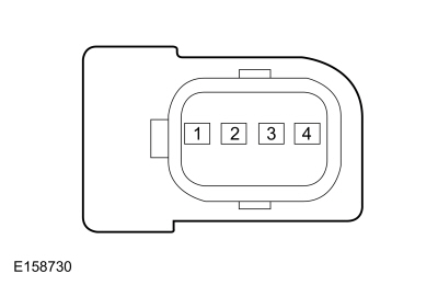 C543, pin 2, component side

 C543, pin 3, component side
 C634, pin 2, component side

 C634, pin 3, component side


 Click here to access Guided Routine (BCM).
 Internet Explorer version 11 or greater is required to perform this Pinpoint Test.
The Luggage Compartment Lid Passive Entry Feature Is Inoperative
Refer to Wiring Diagrams Cell 117 for schematic and connector information.
Normal Operations and Fault Conditions
REFER to: Handles, Locks, Latches and Entry Systems - System Operation and Component Description (501-14 Handles, Locks, Latches and Entry Systems, Description and Operation).
BCM DTC Fault Trigger Conditions
| DTC | Description | Fault Trigger Conditions |
|---|---|---|
| B10C7:01 | Interior Trunk Antenna: General Electrical Failure | Sets when the BCM detects a fault from the keyless entry rear antenna input. |
Possible Causes
- Wiring, terminals or connectors
- Keyless entry rear antenna
- BCM
PINPOINT TEST Z : THE LUGGAGE COMPARTMENT LID PASSIVE ENTRY FEATURE IS INOPERATIVE
| Z1 CHECK THE LUGGAGE COMPARTMENT LID LATCH RELEASE OPERATION | |||||||||||||
Does the luggage compartment lid latch release?
|
|||||||||||||
| Z2 CHECK THE RKE (REMOTE KEYLESS ENTRY) OPERATION | |||||||||||||
Does the luggage compartment lid latch release?
|
|||||||||||||
| Z3 CHECK THE KEYLESS ENTRY REAR ANTENNA | |||||||||||||
Is the resistance between 1 and 10 ohms?
|
|||||||||||||
| Z4 CHECK THE KEYLESS ENTRY REAR ANTENNA CIRCUITS FOR A SHORT TO VOLTAGE | |||||||||||||
Is any voltage present?
|
|||||||||||||
| Z5 CHECK THE KEYLESS ENTRY REAR ANTENNA CIRCUITS FOR A SHORT TO GROUND | |||||||||||||
Are the resistances greater than 10,000 ohms?
|
|||||||||||||
| Z6 CHECK THE KEYLESS ENTRY REAR ANTENNA CIRCUITS FOR AN OPEN | |||||||||||||
Are the resistances less than 3 ohms?
|
|||||||||||||
| Z7 CHECK FOR CORRECT BCM (BODY CONTROL MODULE) OPERATION | |||||||||||||
Is the concern still present?
|
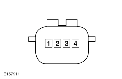 C4817, pin 1, component side

 C4817, pin 2, component side


 Click here to access Guided Routine (BCM).
 Internet Explorer version 11 or greater is required to perform this Pinpoint Test.
U0258:87 or U1A00:00
Refer to Wiring Diagrams Cell 117 for schematic and connector information.
Normal Operation and Fault Conditions
The RTM communicates with the BCM over a LIN-based circuit and, when the network is awake, over the CAN.
RTM DTC Fault Trigger Conditions
| DTC | Description | Fault Trigger Conditions |
|---|---|---|
| U1A00:00 | Private Communication Network: No Sub Type Information | Sets when the RTM detects a fault with the LIN circuit to the BCM. |
BCM DTC Fault Trigger Conditions
| DTC | Description | Fault Trigger Conditions |
|---|---|---|
| U0258:87 | Lost Communication With Radio Transceiver: Missing Message | Sets when the BCM detects a communication fault with the RTM over the LIN circuit. |
Possible Causes
- Wiring, terminals or connectors
- RTM
- BCM
PINPOINT TEST AA : U0258:87 OR U1A00:00
| AA1 CHECK IF THE RTM (RADIO TRANSCEIVER MODULE) AND THE BCM (BODY CONTROL MODULE) PASS THE NETWORK TEST | ||||||||||
Does the RTM and the BCM pass the network test?
|
||||||||||
| AA2 CHECK THE LIN (LOCAL INTERCONNECT NETWORK) CIRCUIT FOR A SHORT TO VOLTAGE | ||||||||||
Is any voltage present?
|
||||||||||
| AA3 CHECK THE LIN (LOCAL INTERCONNECT NETWORK) CIRCUIT FOR A SHORT TO GROUND | ||||||||||
Is the resistance greater than 10,000 ohms?
|
||||||||||
| AA4 CHECK THE LIN (LOCAL INTERCONNECT NETWORK) CIRCUIT FOR AN OPEN | ||||||||||
Is the resistance less than 3 ohms?
|
||||||||||
| AA5 CHECK FOR CORRECT RTM (RADIO TRANSCEIVER MODULE) OPERATION | ||||||||||
Is the concern still present?
|
||||||||||
| AA6 CHECK FOR CORRECT BCM (BODY CONTROL MODULE) OPERATION | ||||||||||
Is the concern still present?
|


 Click here to access Guided Routine (BCM).
 Internet Explorer version 11 or greater is required to perform this Pinpoint Test.
P04B5, P04B9, or P04BA
Refer to Wiring Diagrams Cell 116 for schematic and connector information.
Normal Operation and Fault Conditions
The PCM monitors the fuel filler door ajar switch and sets a DTC if it detects a failure of the fuel filler door ajar input based on conditions after a refueling event.
If the fuel filler door is not fully closed after a refueling event, or the body exterior's fuel filler door is open from erroneously pressing the fuel door release button, a message displays during the third drive cycle to indicate the fuel filler door is not closed and a DTC sets.
PCM DTC Fault Trigger Conditions
| DTC | Description | Fault Trigger Conditions |
|---|---|---|
| P04B5 | Fuel Fill Door Stuck Open | Sets when the PCM detects the body exterior's fuel filler door is open, the vehicle has been running for at least 5 minutes and the vehicle speed is greater than 11 km/h (7 mph) (for example, the fuel filler door was not closed after a refueling event). |
| P04B9 | Fuel Fill Door Position Sensor/Switch Circuit Low | Sets when the PCM detects the fuel filler door ajar switch input is short to ground. A fuel filler door that is never closed can cause this DTC to set. |
| P04BA | Fuel Fill Door Position Sensor/Switch Circuit High | Sets when the PCM detects the body exterior's fuel filler door did not open when the PCM activated the fuel filler door release relay. An open circuit to the fuel filler door ajar switch can cause this DTC to set. |
Possible Causes
- Wiring, terminals or connectors
- Fuel filler door ajar switch (part of the body exterior's fuel filler door assembly)
- PCM
PINPOINT TEST AB : P04B5, P04B9, OR P04BA
| AB1 CHECK FOR MECHANICAL DAMAGE | ||||||||||||||||
Is any damage present?
|
||||||||||||||||
| AB2 CHECK THE PCM (POWERTRAIN CONTROL MODULE) THE CUSTOMER IS REQUESTING OR HAS RECENTLY REQUESTED TO OPEN OR UNLOCK THE FUEL FILL DOOR (FUELDR_REQ) PID (PARAMETER IDENTIFICATION) | ||||||||||||||||
Does the PID momentarily indicate Yes?
|
||||||||||||||||
| AB3 CHECK THE FUEL FILLER DOOR RELEASE USING THE PCM (POWERTRAIN CONTROL MODULE) FUEL FILL DOOR UNLOCK CONTROL OUTPUT IS COMMANDED TO ENABLE STATE (FUELDR_UNLOCK) PID (PARAMETER IDENTIFICATION) | ||||||||||||||||
Does the fuel filler door latch release?
|
||||||||||||||||
| AB4 CHECK THE PCM (POWERTRAIN CONTROL MODULE) THE FUEL FILL DOOR POSITION SENSOR/SWITCH CIRCUIT INPUT (FUELDR_POS_SW) PID (PARAMETER IDENTIFICATION) | ||||||||||||||||
Does the PID indicate Closed with the fuel filler door closed and Open after the fuel filler door latch is released?
|
||||||||||||||||
| AB5 CHECK THE FUEL FILLER DOOR AJAR CIRCUITS FOR A SHORT TO VOLTAGE | ||||||||||||||||
|
NOTE: The fuel filler door electrical connectors can be accessed through an opening in the left side sheet metal inside luggage compartment.
Is any voltage present?
|
||||||||||||||||
| AB6 CHECK THE FUEL FILLER DOOR AJAR CIRCUITS FOR A SHORT TO GROUND | ||||||||||||||||
Are the resistances greater than 10,000 ohms?
|
||||||||||||||||
| AB7 CHECK THE FUEL FILLER DOOR AJAR CIRCUITS FOR AN OPEN | ||||||||||||||||
Are the resistances less than 3 ohms?
|
||||||||||||||||
| AB8 CHECK FOR CORRECT PCM (POWERTRAIN CONTROL MODULE) OPERATION | ||||||||||||||||
Is the concern still present?
|


 Click here to access Guided Routine (PCM).
 Internet Explorer version 11 or greater is required to perform this Pinpoint Test.
B1087:83 or B1087:87
Refer to Wiring Diagrams Cell 117 for schematic and connector information.
Normal Operation and Fault Conditions
The DDM communicates with the left RDM over a LIN circuit. In the event the left RDM fails, the left rear power window and power door lock become inoperative.
The PDM communicates with the right RDM over a LIN circuit. In the event the right RDM fails, the right rear power window and power door lock become inoperative.
DDM/ PDM DTC Fault Trigger Conditions
| DTC | Description | Fault Trigger Conditions |
|---|---|---|
| B1087:83 | LIN Bus "A": Value Of Signal Protection Calculation Incorrect | Sets when the DDM/ PDM detects a fault with the communication from the corresponding RDM. |
| B1087:87 | LIN Bus "A": Signal Invalid | Sets when the DDM/ PDM detects a fault with the communication from the corresponding RDM. |
Possible Causes
- Fuse
- Wiring, terminals or connectors
- RDM
- BCM
Visual Inspection and Diagnostic Pre-checks
- Inspect the BCM fuse 29 (30A) (left RDM) and make sure it is OK.
- Inspect the BCM fuse 30 (30A) (right RDM) and make sure it is OK.
PINPOINT TEST AC : B1087:83 OR B1087:87
| AC1 CHECK IF THE DTC (DIAGNOSTIC TROUBLE CODE) SET IN THE DDM (DRIVER DOOR MODULE) | ||||||||||||||||
Is DTC B1087:83 or B1087:87 set in the DDM?
|
||||||||||||||||
| AC2 ISOLATE THE WINDOW CONTROL SWITCH | ||||||||||||||||
Is DTC B1087:83 or B1087:87 still present?
|
||||||||||||||||
| AC3 CHECK FOR VOLTAGE TO THE REAR DOOR MODULE | ||||||||||||||||
Is the voltage greater than 11 volts?
|
||||||||||||||||
| AC4 CHECK THE REAR DOOR MODULE VOLTAGE SUPPLY CIRCUIT FOR AN OPEN | ||||||||||||||||
Is the resistance less than 3 ohms?
|
||||||||||||||||
| AC5 CHECK THE REAR DOOR MODULE GROUND CIRCUIT FOR AN OPEN | ||||||||||||||||
Is the resistance less than 3 ohms?
|
||||||||||||||||
| AC6 CHECK THE LIN (LOCAL INTERCONNECT NETWORK) CIRCUIT FOR A SHORT TO VOLTAGE | ||||||||||||||||
Is any voltage present?
|
||||||||||||||||
| AC7 CHECK THE LIN (LOCAL INTERCONNECT NETWORK) CIRCUIT FOR A SHORT TO GROUND | ||||||||||||||||
Is the resistance greater than 10,000 ohms?
|
||||||||||||||||
| AC8 CHECK THE CHECK THE LIN (LOCAL INTERCONNECT NETWORK) CIRCUIT FOR AN OPEN | ||||||||||||||||
Is the resistance less than 3 ohms?
|
||||||||||||||||
| AC9 CHECK FOR CORRECT RDM (REAR DOOR MODULE) OPERATION | ||||||||||||||||
Is the concern still present?
|
||||||||||||||||
| AC10 CHECK FOR CORRECT FRONT DOOR MODULE OPERATION | ||||||||||||||||
Is the concern still present?
|
||||||||||||||||
| AC11 CHECK FOR CORRECT BCM (BODY CONTROL MODULE) OPERATION | ||||||||||||||||
Is the concern still present?
|


 Click here to access Guided Routine (BCM).
 Internet Explorer version 11 or greater is required to perform this Pinpoint Test.
B1142:29
Refer to Wiring Diagrams Cell 117 for schematic and connector information.
Normal Operation and Fault Conditions
The DDM/ PDM communicates with the BCM over the CAN. If the DDM/ PDM does not receive the ignition ON status message from the BCM during the self-test, a DTC sets.
DDM/ PDM DTC Fault Trigger Conditions
| DTC | Description | Fault Trigger Conditions |
|---|---|---|
| B1142:29 | Ignition Status 1: Signal Invalid | Sets when the DDM/ PDM has not received the ignition ON message from the BCM during the self-test. |
Possible Causes
- Ignition is off
- Network concern
PINPOINT TEST AD : B1142:29
| AD1 CHECK THE IGNITION STATE | ||||
Is the ignition status LED flashing or on solidly?
|
U0140:00
Normal Operation and Fault Conditions
The DDM/ PDM communicates with the BCM over the CAN. If the DDM/ PDM does not receive messages from the BCM, features such as the puddle lamps, exterior mirror turn signal and door switch illumination can be inoperative.
DDM/ PDM DTC Fault Trigger Conditions
| DTC | Description | Fault Trigger Conditions |
|---|---|---|
| U0140:00 | Lost Communication With Body Control Module: No Sub-Type Information | Sets when the DDM/ PDM detects data messages are missing from the BCM. |
Possible Causes
- Network communication concern
- DDM/ PDM
- BCM
PINPOINT TEST AE : U0140:00
| AE1 VERIFY THE CUSTOMER CONCERN | ||||
Is an observable symptom present?
|
||||
| AE2 CHECK THE COMMUNICATION NETWORK | ||||
Does the BCM pass the network test?
|
||||
| AE3 CHECK FOR BCM (BODY CONTROL MODULE) DIAGNOSTIC TROUBLE CODES (DTCS) | ||||
Are any voltage related Diagnostic Trouble Codes (DTCs) present?
|
||||
| AE4 RECHECK THE DDM (DRIVER DOOR MODULE) OR PDM (PASSENGER DOOR MODULE) DIAGNOSTIC TROUBLE CODES (DTCS) | ||||
|
NOTE: If new modules were installed prior to the DTC being set, the module configuration may be incorrectly set during PMIor the PMI may not have been performed.
Is DTC U0140:00 still present?
|
||||
| AE5 CHECK FOR DTC (DIAGNOSTIC TROUBLE CODE) U0140 SET IN OTHER MODULES | ||||
Is DTC U0140 set in other modules?
|
 Click here to access Guided Routine (BCM).
 Internet Explorer version 11 or greater is required to perform this Pinpoint Test.
U0164:00
Normal Operation and Fault Conditions
The DDM/ PDM communicates with the FCIM over the CAN. If the DDM/ PDM does not receive messages from the FCIM, features such as the mirror defrost can be inoperative.
DDM/ PDM DTC Fault Trigger Conditions
| DTC | Description | Fault Trigger Conditions |
|---|---|---|
| U0164:00 | Lost Communication With HVAC Control Module: No Sub-Type Information | Sets when the DDM/ PDM detects data messages are missing from the FCIM. |
Possible Causes
- Network communication concern
- DDM/ PDM
- FCIM
PINPOINT TEST AF : U0164:00
| AF1 VERIFY THE CUSTOMER CONCERN | ||||
Is an observable symptom present?
|
||||
| AF2 CHECK THE COMMUNICATION NETWORK | ||||
Does the FCIM pass the network test?
|
||||
| AF3 CHECK FOR FCIM (FRONT CONTROLS INTERFACE MODULE) DIAGNOSTIC TROUBLE CODES (DTCS) | ||||
Are any voltage related Diagnostic Trouble Codes (DTCs) present?
|
||||
| AF4 RECHECK THE DDM (DRIVER DOOR MODULE) OR PDM (PASSENGER DOOR MODULE) DIAGNOSTIC TROUBLE CODES (DTCS) | ||||
|
NOTE: If new modules were installed prior to the DTC being set, the module configuration may be incorrectly set during PMIor the PMI may not have been performed.
Is DTC U0164:00 still present?
|
||||
| AF5 CHECK FOR DTC (DIAGNOSTIC TROUBLE CODE) U0164 SET IN OTHER MODULES | ||||
Is DTC U0164 set in other modules?
|
 Click here to access Guided Routine (FCIM).
 Internet Explorer version 11 or greater is required to perform this Pinpoint Test.
U0208:00
Normal Operation and Fault Conditions
The DDM/ PDM communicate with the DSM over the CAN. If the DDM/ PDM does not receive messages from the DSM, features such as the memory mirror position can be inoperative.
DDM/ PDM DTC Fault Trigger Conditions
| DTC | Description | Fault Trigger Conditions |
|---|---|---|
| U0208:00 | Lost Communication With "Seat Control Module A": No Sub-Type Information | Sets when the DDM/ PDM detects data messages are missing from the DSM. |
Possible Causes
- Network communication concern
- DDM/ PDM
- DSM
PINPOINT TEST AG : U0208:00
| AG1 VERIFY THE CUSTOMER CONCERN | ||||
Is an observable symptom present?
|
||||
| AG2 CHECK THE COMMUNICATION NETWORK | ||||
Does the DSM pass the network test?
|
||||
| AG3 CHECK FOR DSM (DRIVER FRONT SEAT MODULE) DIAGNOSTIC TROUBLE CODES (DTCS) | ||||
Are any voltage related Diagnostic Trouble Codes (DTCs) present?
|
||||
| AG4 RECHECK THE DDM (DRIVER DOOR MODULE) OR PDM (PASSENGER DOOR MODULE) DIAGNOSTIC TROUBLE CODES (DTCS) | ||||
|
NOTE: If new modules were installed prior to the DTC being set, the module configuration may be incorrectly set during PMI or the PMI may not have been performed.
Is DTC U0208:00 still present?
|
||||
| AG5 CHECK FOR DTC (DIAGNOSTIC TROUBLE CODE) U0208 SET IN OTHER MODULES | ||||
Is DTC U0208 set in other modules?
|
U0232:00
Normal Operation and Fault Conditions
The DDM communicates with the SODL over the CAN. If the DDM does not receive messages from the SODL, the side obstacle detection feature can be inoperative for the left side.
DDM DTC Fault Trigger Conditions
| DTC | Description | Fault Trigger Conditions |
|---|---|---|
| U0232:00 | Lost Communication With Side Obstacle Detection Control Module - Left: No Sub-Type Information | Sets when the DDM detects data messages are missing from the SODL. |
Possible Causes
- Network communication concern
- DDM
- SODL
PINPOINT TEST AH : U0232:00
| AH1 VERIFY THE CUSTOMER CONCERN | ||||
Is an observable symptom present?
|
||||
| AH2 CHECK THE COMMUNICATION NETWORK | ||||
Does the SODL pass the network test?
|
||||
| AH3 CHECK FOR SODL (SIDE OBSTACLE DETECTION CONTROL MODULE LH) DIAGNOSTIC TROUBLE CODES (DTCS) | ||||
Are any voltage related Diagnostic Trouble Codes (DTCs) present?
|
||||
| AH4 RECHECK THE DDM (DRIVER DOOR MODULE) DIAGNOSTIC TROUBLE CODES (DTCS) | ||||
|
NOTE: If new modules were installed prior to the DTC being set, the module configuration may be incorrectly set during PMI or the PMI may not have been performed.
Is DTC U0232:00 still present?
|
||||
| AH5 CHECK FOR DTC (DIAGNOSTIC TROUBLE CODE) U0232 SET IN OTHER MODULES | ||||
Is DTC U0232 set in other modules?
|
U0233:00
Normal Operation and Fault Conditions
The PDM communicates with the SODR over the CAN. If the PDM does not receive messages from the SODR, the side obstacle detection feature can be inoperative for the right side.
PDM DTC Fault Trigger Conditions
| DTC | Description | Fault Trigger Conditions |
|---|---|---|
| U0233:00 | Lost Communication With Side Obstacle Detection Control Module - Right: No Sub-Type Information | Sets when the PDM detects data messages are missing from the SODR. |
Possible Causes
- Network communication concern
- PDM
- SODR
PINPOINT TEST AI : U0233:00
| AI1 VERIFY THE CUSTOMER CONCERN | ||||
Is an observable symptom present?
|
||||
| AI2 CHECK THE COMMUNICATION NETWORK | ||||
Does the SODR pass the network test?
|
||||
| AI3 CHECK FOR SODR (SIDE OBSTACLE DETECTION CONTROL MODULE RH) DIAGNOSTIC TROUBLE CODES (DTCS) | ||||
Are any voltage related Diagnostic Trouble Codes (DTCs) present?
|
||||
| AI4 RECHECK THE PDM (PASSENGER DOOR MODULE) DIAGNOSTIC TROUBLE CODES (DTCS) | ||||
|
NOTE: If new modules were installed prior to the DTC being set, the module configuration may be incorrectly set during PMI or the PMI may not have been performed.
Is DTC U0233:00 still present?
|
||||
| AI5 CHECK FOR DTC (DIAGNOSTIC TROUBLE CODE) U0233 SET IN OTHER MODULES | ||||
Is DTC U0233 set in other modules?
|
U0294:00
Normal Operation and Fault Conditions
The DDM/ PDM communicates with the PCM over the CAN. If the DDM/ PDM does not receive messages from the PCM, the window inhibit feature during a start/stop event can be inoperative.
DDM/ PDM DTC Fault Trigger Conditions
| DTC | Description | Fault Trigger Conditions |
|---|---|---|
| U0294:00 | Lost Communication With Powertrain Control Monitor Module: No Sub-Type Information | Sets when the DDM/ PDM detects data messages are missing from the PCM. |
Possible Causes
- Network communication concern
- DDM/ PDM
- PCM
PINPOINT TEST AJ : U0294:00
| AJ1 VERIFY THE CUSTOMER CONCERN | ||||
Is an observable symptom present?
|
||||
| AJ2 CHECK THE COMMUNICATION NETWORK | ||||
Does the SODL pass the network test?
|
||||
| AJ3 CHECK FOR PCM (POWERTRAIN CONTROL MODULE) DIAGNOSTIC TROUBLE CODES (DTCS) | ||||
Are any voltage related Diagnostic Trouble Codes (DTCs) present?
|
||||
| AJ4 RECHECK THE DDM (DRIVER DOOR MODULE) / PDM (PASSENGER DOOR MODULE) DIAGNOSTIC TROUBLE CODES (DTCS) | ||||
|
NOTE: If new modules were installed prior to the DTC being set, the module configuration may be incorrectly set during PMI or the PMI may not have been performed.
Is DTC U0294:00 still present?
|
||||
| AJ5 CHECK FOR DTC (DIAGNOSTIC TROUBLE CODE) U0294 SET IN OTHER MODULES | ||||
Is DTC U0294 set in other modules?
|
 Click here to access Guided Routine (PCM).
 Internet Explorer version 11 or greater is required to perform this Pinpoint Test.
P1594 or P1595
REFER to: Handles, Locks, Latches and Entry Systems - System Operation and Component Description (501-14 Handles, Locks, Latches and Entry Systems, Description and Operation).
Normal Operation and Fault Conditions
When the BCM receives a request to remote start the vehicle, it first checks to make sure conditions exist to allow it to start (for example, the hood and doors closed, vehicle in PARK, no powertrain concerns). If the required conditions are correct, the BCM starts the vehicle and allows it to run for a predetermined amount of time, determined by the setting selected from the message center.
SOBDMC DTC Fault Trigger Conditions
| DTC | Description | Fault Trigger Conditions |
|---|---|---|
| P1594 | Forced Engine Shutdown - Remote Start System Fault, No Unattended Vehicle Timeout | Sets when the SOBDMC detects the remote start has been active for more than 30 minutes continuously. |
| P1595 | Forced Engine Shutdown - Remote Start System Fault, Transmission Range Not In Park Position | Sets when the SOBDMC detects the remote start is active with the transmission not in PARK. |
Possible Causes
- Powertrain concern
- BCM
PINPOINT TEST AK : P1594 OR P1595
| AK1 CHECK FOR PCM (POWERTRAIN CONTROL MODULE) DIAGNOSTIC TROUBLE CODES (DTCS) | ||||
Are any PCM Diagnostic Trouble Codes (DTCs) present?
|
||||
| AK2 CHECK FOR BCM (BODY CONTROL MODULE) DIAGNOSTIC TROUBLE CODES (DTCS) | ||||
Are any BCM Diagnostic Trouble Codes (DTCs) present?
|
 Click here to access Guided Routine (BCM).
 Internet Explorer version 11 or greater is required to perform this Pinpoint Test.
 Door Latch Lubrication. General Procedures
Special Tool(s) /
General Equipment
Flat-Bladed Screwdriver
Materials
Name
Specification
Motorcraft® Multi-Purpose Grease SprayXL-5-A
ESB-M1C93-B
Activation
NOTE:
Typical left front door shown, others similar...
Other information:
Ford Fusion 2013–2020 Service Manual: Transmission Fluid Auxiliary Pump. Removal and Installation
Removal With the vehicle in NEUTRAL, position it on a hoist. Refer to: Jacking and Lifting - Overview (100-02 Jacking and Lifting, Description and Operation). Refer to: Engine Front Undershield (501-02 Front End Body Panels, Removal and Installation)...
Ford Fusion 2013–2020 Service Manual: Seatbelt Tongue Rotated On Belt. General Procedures
Adjustment NOTE: Typical seatbelt tongue shown, others similar. Fold the seatbelt as indicated. Feed the folded portion of the seatbelt into the seatbelt tongue. Pull the seatbelt through the seatbelt tongue to remove the twist in the seatbelt...
Categories
- Manuals Home
- 2nd Generation Ford Fusion Owners Manual
- 2nd Generation Ford Fusion Service Manual
- Under Hood Overview - 1.5L EcoBoost™, 2.0L EcoBoost™, 2.5L, 2.7L EcoBoost™
- Electronic Parking Brake (EPB) Service Mode Activation and Deactivation. General Procedures
- Engine
- New on site
- Most important about car
Cross Traffic Alert System Sensors
The sensors are behind the rear bumper on both sides of your vehicle.