Ford Fusion: Automatic Transmission External Controls - 6-Speed Automatic Transmission – 6F35 / Selector Lever Cable - 1.5L EcoBoost (118kW/160PS) – I4. Removal and Installation
Removal
-
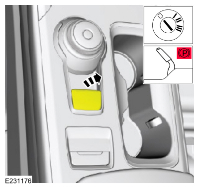
Turn the ignition switch to the OFF position and apply the parking brake.
-
Remove the air cleaner.
Refer to: Air Cleaner (303-12A Intake Air Distribution and Filtering - 1.5L EcoBoost (118kW/160PS) – I4, Removal and Installation).
-
Remove the air cleaner outlet pipe.
Refer to: Air Cleaner Outlet Pipe (303-12A Intake Air Distribution and Filtering - 1.5L EcoBoost (118kW/160PS) – I4, Removal and Installation).
-
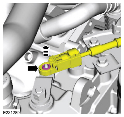
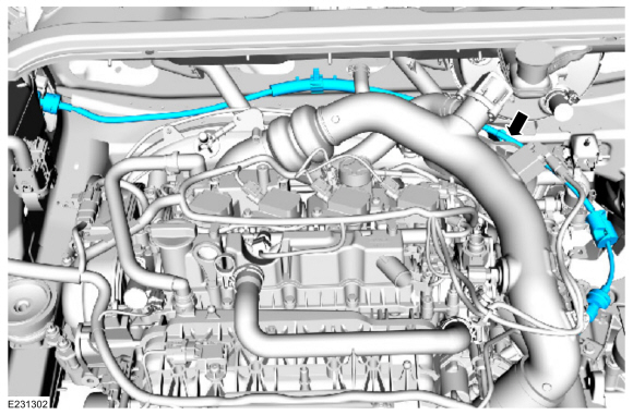
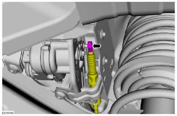
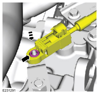
Disconnect the selector lever cable from the transmission manual lever.
-
Remove the selector cable retaining clip bolt.
-
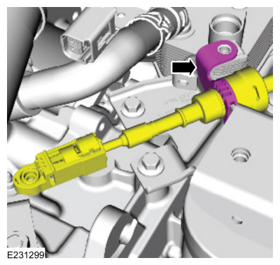
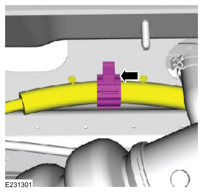
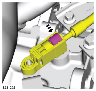
Release the clip and detach the selector lever cable from the selector lever cable bracket.
-
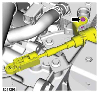
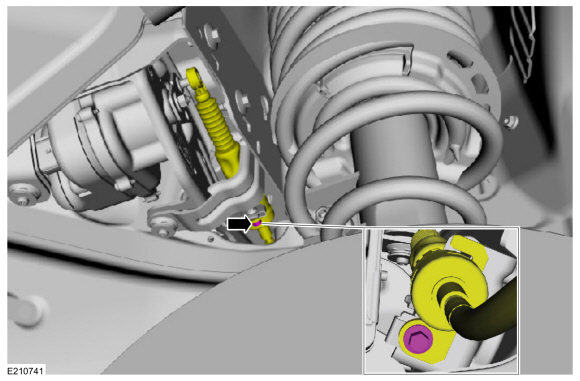
Remove the selector lever cable nut.
-
Detach the selector lever cable retainer.
-
Remove the RH fender splash shield.
Refer to: Fender Splash Shield (501-02 Front End Body Panels, Removal and Installation).
-
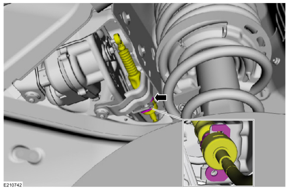
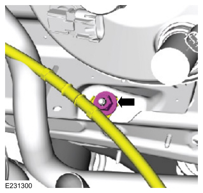
Detach the selector lever cable from the TRCM lever.
-
Remove the selector lever cable retaining clip bolt.
-
Release the tab and detach the selector lever cable from the selector lever cable bracket.
-
Remove the selector lever cable.
Installation
-
Position the selector lever cable in the vehicle.
-
Attach the selector lever cable to the selector lever cable bracket.
-
Install the selector lever cable retaining clip bolt.
Torque:
62 lb.in (7 Nm)
-
Attach the selector lever cable to the TRCM lever.
-
Install the RH fender splash shield.
Refer to: Fender Splash Shield (501-02 Front End Body Panels, Removal and Installation).
-
Attach the selector lever cable retainer.
-
Install the selector lever cable nut.
Torque:
80 lb.in (9 Nm)
-
Attach the selector lever cable to the selector lever cable bracket.
-
Install the selector cable retaining clip bolt.
Torque:
62 lb.in (7 Nm)
-
Using the diagnostic scan tool select the cable adjustment mode.
-
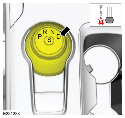
NOTE:
The GSM will alternate flashing D or N and S simultaneously.
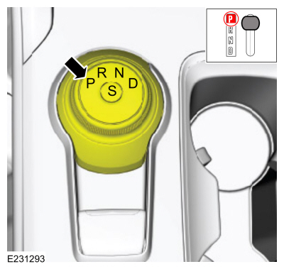
Choose D on the GSM.
-
NOTE:
Verify D is illuminated on the IPC.
Position the manual control lever in D.
-
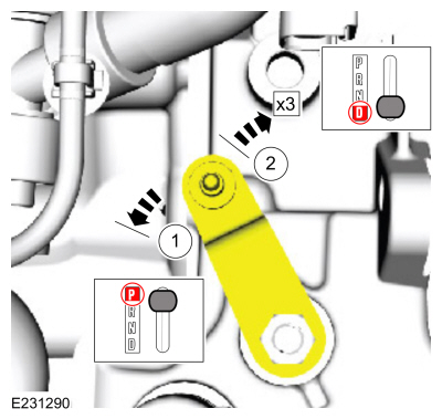
Rotate the manual control lever counterclockwise until it stops.
-
Rotate the manual control lever 3 detents into D.
-
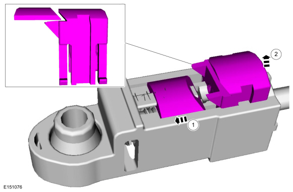
Unlock the adjuster.
-
Move the slide to the left.
-
While holding the slide, position the adjuster lock upward.
-
Connect the selector lever cable to the transmission manual lever.
-
Snap the adjuster lock into place.
-
Choose P on the GSM.
-
Clear any DTCs.
-
Shift the transmission through the ranges starting in P, then R, then N, then D, then N, then R and then back to P.
-
Check for DTCs.
-
Disconnect the scan tool.
-
Release the parking brake.
-
Install the air cleaner outlet pipe.
Refer to: Air Cleaner Outlet Pipe (303-12A Intake Air Distribution and Filtering - 1.5L EcoBoost (118kW/160PS) – I4, Removal and Installation).
-
Install the air cleaner.
Refer to: Air Cleaner (303-12A Intake Air Distribution and Filtering - 1.5L EcoBoost (118kW/160PS) – I4, Removal and Installation).
-
Verify that the vehicle starts in P and N only and that the reverse lamps illuminate in R.
Special Tool(s) /
General Equipment
Interior Trim Remover
Removal
NOTE:
It is not necessary to carry out a PMI when installing a new GSM unless specifically instructed to do so in a TSB, GSB, FSA or SSM...
Removal
Turn the ignition switch to the OFF position and apply the parking brake.
Remove the air cleaner assembly...
Other information:
Removal
NOTE:
Removal steps in this procedure may contain installation details.
Release the tabs, disconnect the USB\ cable and remove the media hub.
Installation
To install, reverse the removal procedure...
DTC Chart: BCM
Diagnostics in this manual assume a certain skill level and knowledge of Ford-specific diagnostic practices. REFER to: Diagnostic Methods (100-00 General Information, Description and Operation).
BCM
DTC Chart
DTC
Description
Action
B1277:11
Reverse Lamp: Circuit Short To Ground
GO to Pinpoint Test..


 Gear Shift Module (GSM). Removal and Installation
 Selector Lever Cable Bushing. Removal and Installation