Ford Fusion: Suspension System - General Information / Ride Height Measurement. General Procedures
Ford Fusion 2013–2020 Service Manual / Chassis / Suspension / Suspension System - General Information / Ride Height Measurement. General Procedures
Special Tool(s) / General Equipment
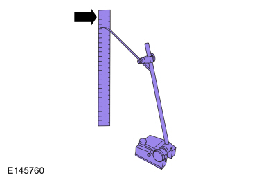
| Surface Gauge |
Check
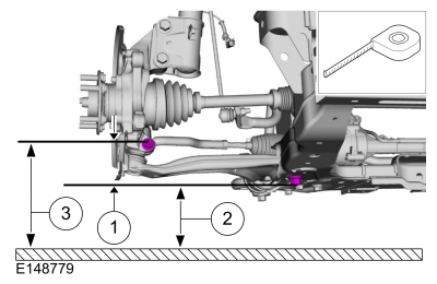
NOTE: Ride Height Measurement - Front
NOTE: Make sure that the vehicle is positioned on a flat, level surface and the tires are inflated to the correct pressure. Vehicle should have a full tank of fuel.
-
-
Ride height = 3-2
-
Measurement 2
-
Measurement 3
Use the General Equipment: Surface Gauge
-
Ride height = 3-2
 |
-
With the surface gauge positioned on a flat, level
surface, record the measurement of the surface gauge position
(measurement 3).
Use the General Equipment: Surface Gauge
 |
-
Subtract measurement 2 from measurement 3 to obtain the front ride height.
Check
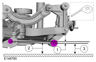
NOTE: Ride Height Measurement - Rear
NOTE: Make sure that the vehicle is positioned on a flat, level surface and the tires are inflated to the correct pressure. Vehicle should have a full tank of fuel.
-
-
Ride height = 2-3
-
Measurement 2
-
Measurement 3
Use the General Equipment: Surface Gauge
-
Ride height = 2-3
 |
-
Measure the distance between the flat level surface and the toe link inboard cam bolt (measurement 2).
-
Measure the distance between the flat level surface and
the center of the toe link outboard bolt (measurement 3).
-
Subtract measurement 3 from measurement 2 to obtain the rear ride height.
 Rear Camber Adjustment. General Procedures
Special Tool(s) /
General Equipment
Wheel Alignment System
Adjustment
NOTICE:
Suspension fasteners are critical parts that affect the
performance of vital components and systems...
 Front Camber Adjustment. General Procedures
Special Tool(s) /
General Equipment
Wheel Alignment System
Adjustment
NOTICE:
Suspension fasteners are critical parts that affect the
performance of vital components and systems...
Other information:
Ford Fusion 2013–2020 Owners Manual: Interior Luggage Compartment Release
WARNING: Keep vehicle doors and luggage compartment locked and keep keys and remote transmitters out of a child’s reach. Unsupervised children could lock themselves in the trunk and risk injury. Children should be taught not to play in vehicles...
Ford Fusion 2013–2020 Owners Manual: Daytime Running Lamps - Vehicles With: Configurable Daytime Running Lamps. Daytime Running Lamps - Vehicles With: Daytime Running Lamps (DRL)
Daytime Running Lamps - Vehicles With: Configurable Daytime Running Lamps WARNING: The daytime running lamps system does not activate the rear lamps and may not provide adequate lighting during low visibility driving conditions. Make sure you switch the headlamps on, as appropriate, during all low visibility conditions...
Categories
- Manuals Home
- 2nd Generation Ford Fusion Owners Manual
- 2nd Generation Ford Fusion Service Manual
- Cylinder Head. Removal and Installation
- Starter Motor. Removal and Installation
- Automatic Transmission - 6-Speed Automatic Transmission – 6F35
- New on site
- Most important about car
Cross Traffic Alert System Sensors
The sensors are behind the rear bumper on both sides of your vehicle.
Copyright © 2026 www.fofusion2.com