Ford Fusion: Rear View Mirrors / Rear View Mirrors. Diagnosis and Testing
DTC Chart: DDM
Diagnostics in this manual assume a certain skill level and knowledge of Ford-specific diagnostic practices.
REFER to: Diagnostic Methods (100-00 General Information, Description and Operation).
| DTC | Description | Action |
| B1163:11 | Left Mirror Heater Output: Circuit Short To Ground | GO to Pinpoint Test D |
| B1163:15 | Left Mirror Heater Output: Circuit Short To Battery Or Open | GO to Pinpoint Test D |
| B11F6:11 | Driver Folding Mirror Motor: Circuit Short To Ground | GO to Pinpoint Test E |
| B11F6:15 | Driver Folding Mirror Motor: Circuit Short To Battery or Open | GO to Pinpoint Test E |
| B1C06:11 | Driver Up/Down And Common Mirror Motor: Circuit Short To Ground |
|
| B1C06:15 | Driver Up/Down And Common Mirror Motor: Circuit Short To Battery or Open |
|
| B1C09:11 | Driver Left/Right Mirror Motor: Circuit Short To Ground | GO to Pinpoint Test B |
| B1C09:15 | Driver Left/Right Mirror Motor: Circuit Short To Battery Or Open | GO to Pinpoint Test B |
| B1C10:11 | Driver Up/Down Mirror Motor: Circuit Short To Ground | GO to Pinpoint Test B |
| B1C10:15 | Driver Up/Down Mirror Motor: Circuit Short To Battery Or Open | GO to Pinpoint Test B |
| B1C13:11 | Driver Up/Down Mirror Motor Feedback: Circuit Short To Ground | GO to Pinpoint Test C |
| B1C13:15 | Driver Up/Down Mirror Motor Feedback: Circuit Short To Battery Or Open | GO to Pinpoint Test C |
| B1C14:11 | Driver Left/Right Mirror Motor Feedback: Circuit Short To Ground | GO to Pinpoint Test C |
| B1C14:15 | Driver Left/Right Mirror Motor Feedback: Circuit Short To Battery Or Open | GO to Pinpoint Test C |
| C1B15:11 | Sensor Supply Voltage B: Circuit Short To Ground | GO to Pinpoint Test C |
| C1B15:15 | Sensor Supply Voltage B: Circuit Short To Battery or Open | GO to Pinpoint Test C |
| All other DDM Diagnostic Trouble Codes (DTCs) | - |
REFER to: Locks, Latches and Entry Systems (501-14 Handles, Locks, Latches and Entry Systems, Diagnosis and Testing). |
DTC Chart: PDM
Diagnostics in this manual assume a certain skill level and knowledge of Ford-specific diagnostic practices.
REFER to: Diagnostic Methods (100-00 General Information, Description and Operation).
| DTC | Description | Action |
| B1164:11 | Right Mirror Heater Output: Circuit Short To Ground | GO to Pinpoint Test D |
| B1164:15 | Right Mirror Heater Output: Circuit Short To Battery Or Open | GO to Pinpoint Test D |
| B11F7:11 | Passenger Folding Mirror Motor: Circuit Short To Ground | GO to Pinpoint Test E |
| B11F7:15 | Passenger Folding Mirror Motor: Circuit Short To Battery or Open | GO to Pinpoint Test E |
| B1C08:11 | Passenger Left/Right and Common Mirror Motor: Circuit Short To Ground |
|
| B1C08:15 | Passenger Left/Right and Common Mirror Motor: Circuit Short To Battery or Open |
|
| B1C11:11 | Passenger Left/Right Mirror Motor: Circuit Short To Ground | GO to Pinpoint Test B |
| B1C11:15 | Passenger Left/Right Mirror Motor: Circuit Short To Battery Or Open | GO to Pinpoint Test B |
| B1C12:11 | Passenger Up/Down Mirror Motor: Circuit Short To Ground | GO to Pinpoint Test B |
| B1C12:15 | Passenger Up/Down Mirror Motor: Circuit Short To Battery Or Open | GO to Pinpoint Test B |
| B1C15:11 | Passenger Up/Down Mirror Motor Feedback: Circuit Short To Ground | GO to Pinpoint Test C |
| B1C15:15 | Passenger Up/Down Mirror Motor Feedback: Circuit Short To Battery Or Open | GO to Pinpoint Test C |
| B1C16:11 | Passenger Left/Right Mirror Motor Feedback: Circuit Short To Ground | GO to Pinpoint Test C |
| B1C16:15 | Passenger Left/Right Mirror Motor Feedback: Circuit Short To Battery Or Open | GO to Pinpoint Test C |
| C1B15:11 | Sensor Supply Voltage B: Circuit Short To Ground | GO to Pinpoint Test C |
| C1B15:15 | Sensor Supply Voltage B: Circuit Short To Battery or Open | GO to Pinpoint Test C |
| All other PDM Diagnostic Trouble Codes (DTCs) | - |
REFER to: Locks, Latches and Entry Systems (501-14 Handles, Locks, Latches and Entry Systems, Diagnosis and Testing). |
DTC Chart: IPMA
Diagnostics in this manual assume a certain skill level and knowledge of Ford-specific diagnostic practices.
REFER to: Diagnostic Methods (100-00 General Information, Description and Operation).
| DTC | Description | Action |
| B1286:14 | Interior Mirror: Circuit Short To Ground or Open | GO to Pinpoint Test G |
| All other IPMA Diagnostic Trouble Codes (DTCs) | - |
REFER to: Lane Keeping System (419-07 Lane Keeping System, Diagnosis and Testing). |
DTC Chart: FCIM
Diagnostics in this manual assume a certain skill level and knowledge of Ford-specific diagnostic practices.
REFER to: Diagnostic Methods (100-00 General Information, Description and Operation).
| DTC | Description | Action |
| B1C83:12 | Rear Defog Relay: Circuit Short to Battery |
See DTC Chart: FCIM. REFER to: Glass, Frames and Mechanisms (501-11 Glass, Frames and Mechanisms, Diagnosis and Testing). |
| B1C83:14 | Rear Defog Relay: Circuit Short To Ground or Open | |
| All other FCIM Diagnostic Trouble Codes (DTCs) | - |
REFER to: Climate Control System - Vehicles With: Dual Automatic Temperature Control (DATC) (412-00 Climate Control System - General Information, Diagnosis and Testing). REFER to: Climate Control System - Vehicles With: Electronic Manual Temperature Control (EMTC) (412-00 Climate Control System - General Information, Diagnosis and Testing). |
Symptom Chart(s)
Symptom Chart: Rear View Mirrors - Exterior
Diagnostics in this manual assume a certain skill level and knowledge of Ford-specific diagnostic practices.
REFER to: Diagnostic Methods (100-00 General Information, Description and Operation).
NOTE: Clean the entire mirror assembly and glass to assist in verification of the customer concern and/or impact damage. Do not clean any mirror glass or housing with an ice scraper, razor blade, abrasive pad, harsh chemicals or petroleum based cleaning products, as these may damage the mirror glass and/or housing.
| Condition | Possible Causes | Action |
| One or both exterior mirrors fold inward due to wind pressure |
|
|
| Both exterior mirrors are inoperative |
|
|
| A single mirror is inoperative | Refer to the Pinpoint Test | GO to Pinpoint Test A |
| A single exterior mirror does not function correctly in all directions | Refer to the Pinpoint Test | GO to Pinpoint Test B |
| The exterior mirror memory recall feature is inoperative/does not operate correctly | Refer to the Pinpoint Test | GO to Pinpoint Test C |
| The mirrors make unexpected movements without exterior mirror control switch input |
|
|
| A single heated exterior mirror is inoperative or always on | High ambient air temperature | The DDM and PDM automatically deactivate the heated exterior mirrors when the ambient air temperature is above 30° C ( 86° F). This is normal operation. |
| Refer to the Pinpoint Test | GO to Pinpoint Test D | |
| Both heated exterior mirrors are inoperative |
|
DIAGNOSE the rear window defrost system. See Symptom Chart: The defrost system is inoperative. REFER to: Glass, Frames and Mechanisms (501-11 Glass, Frames and Mechanisms, Diagnosis and Testing). |
| The LH and RH heated exterior mirrors do not defrost at the same rate | Normal operation of the heated exterior mirror | No action required, the system is operating correctly at this time. |
| The heated exterior mirrors do not operate from the voice command only |
|
|
| The heated exterior mirrors do not operate from the touchscreen command only |
|
|
| The LH and/or RH power folding mirror is inoperative/does not operate correctly | Refer to the Pinpoint Test | GO to Pinpoint Test E |
| The LH and/or RH automatic power folding mirror feature is inoperative (power folding mirrors can be activated manually using the exterior mirror fold switch) | Refer to the Pinpoint Test | GO to Pinpoint Test F |
| The LH and RH power folding mirror do not fold and/or unfold at the same rate of speed | Normal operation of the power folding mirror | No action required, the system is operating correctly at this time. |
| The LH auto-dimming exterior mirror is inoperative or always in a darkened state | Refer to the Pinpoint Test | GO to Pinpoint Test G |
| An exterior mirror selection switch LED is inoperative (exterior mirror selection switch functions normally) | Exterior mirror selection switch |
INSTALL a new LH front door window control switch. REFER to: Front Door Window Control Switch (501-11 Glass, Frames and Mechanisms, Removal and Installation). |
| The exterior mirror puddle lamp is inoperative or always on |
|
See Symptom Chart: Interior Lighting. REFER to: Interior Lighting (417-02 Interior Lighting, Diagnosis and Testing). |
| The exterior mirror turn signal is inoperative or always on |
|
See Symptom Chart: Turn Signal and Hazard Lamps. REFER to: Turn Signal and Hazard Lamps (417-01 Exterior Lighting, Diagnosis and Testing). |
| The BLIS®/ CTA indicator is inoperative or always on |
|
See Symptom Chart - BLIS and/or Symptom Chart - CTA. REFER to: Blind Spot Information System (419-04 Side and Rear Vision, Diagnosis and Testing). |
Symptom Chart: Rear View Mirrors - Interior
Diagnostics in this manual assume a certain skill level and knowledge of Ford-specific diagnostic practices.
REFER to: Diagnostic Methods (100-00 General Information, Description and Operation).
NOTE: Clean the entire mirror assembly and glass to assist in verification of the customer concern and/or impact damage. Do not clean any mirror glass or housing with an ice scraper, razor blade, abrasive pad, harsh chemicals or petroleum based cleaning products, as these may damage the mirror glass and/or housing.
| Condition | Possible Causes | Action |
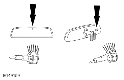
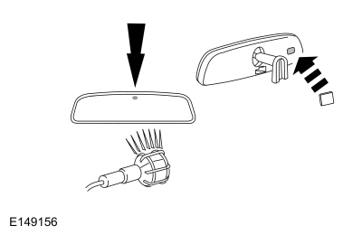
| The interior mirror is blemished | Interior mirror glass/housing is dirty |
NOTE: Do not clean the housing or glass of any mirror with harsh abrasives, fuel or other petroleum-based cleaning products. CLEAN the affected interior mirror surface |
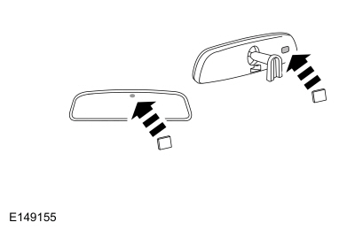
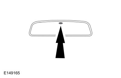
| The interior mirror vibrates or is loose | Interior mirror mounting loose |
If the mirror is still on the windshield, do not remove.
ATTEMPT to fully seat the mirror first. If the mirror is still loose or
vibrates, REMOVE and REINSTALL the mirror. If the condition still
exists, INSTALL a new interior mirror. REFER to: Interior Rear View Mirror (501-09 Rear View Mirrors, Removal and Installation). |
| The interior auto-dimming mirror does not operate correctly | Refer to the Pinpoint Test | GO to Pinpoint Test H |
Symptom Chart: Rear View Mirrors - NVH
Diagnostics in this manual assume a certain skill level and knowledge of Ford-specific diagnostic practices.
REFER to: Diagnostic Methods (100-00 General Information, Description and Operation).
NOTE: Clean the entire mirror assembly and glass to assist in verification of the customer concern and/or impact damage. Do not clean any mirror glass or housing with an ice scraper, razor blade, abrasive pad, harsh chemicals or petroleum based cleaning products, as these may damage the mirror glass and/or housing.
| Condition | Possible Causes | Action |
| Exterior mirror housing vibrates or is loose |
|
SYNCHRONIZE the power folding mirrors. REFER to: Power Mirrors Synchronization (501-09 Rear View Mirrors, General Procedures). |
|
TIGHTEN the exterior mirror mounting nuts. REFER to: Exterior Mirror (501-09 Rear View Mirrors, Removal and Installation). |
|
|
If possible, REMOVE the aftermarket parts and ROAD TEST the vehicle. If the concern is no longer present, ADVISE the customer that the aftermarket components were causing the undesired vibration. | |
| Exterior mirror glass vibrates or is loose |
|
PRESS the center of the exterior mirror
glass up, down, left and right to make sure that the exterior mirror
glass is seated correctly. If the exterior mirror glass is still loose,
REMOVE the exterior mirror glass. INSPECT the exterior mirror backing
plate for damage. INSPECT the exterior mirror motor mounting screws and
TIGHTEN if necessary. If the exterior mirror backing plate is damaged,
INSTALL a new exterior mirror glass. REFER to: Exterior Mirror (501-09 Rear View Mirrors, Removal and Installation). |
| Wind noise | Foam gasket between exterior mirror housing and door is misaligned or damaged |
VERIFY the gasket is in good condition.
If necessary, REPOSITION the gasket between the exterior mirror housing
and the door or REPAIR the foam gasket as necessary. The foam gasket is
not serviceable and if it cannot be repaired, INSTALL a new exterior
mirror. REFER to: Exterior Mirror (501-09 Rear View Mirrors, Removal and Installation). |
| Exterior mirror is not correctly fitted to the door |
VERIFY there are no gaps between the
exterior mirror and the door. If necessary, LOOSEN the exterior mirror
nuts and REPOSITION the exterior mirror as necessary. REFER to: Exterior Mirror (501-09 Rear View Mirrors, Removal and Installation). |
|
| Exterior mirror impact damage | INSPECT the exterior mirror to ensure that there is no damage to the housing or glass. | |
| The interior mirror vibrates or is loose | Interior mirror mounting loose |
If the mirror is still on the windshield, do not remove.
ATTEMPT to fully seat the mirror first. If the mirror is still loose or
vibrates, REMOVE and REINSTALL the mirror. If the condition still
exists, INSTALL a new interior mirror. REFER to: Interior Rear View Mirror (501-09 Rear View Mirrors, Removal and Installation). |
Pinpoint Tests
A Single Mirror Is Inoperative
Refer to Wiring Diagrams Cell 124 for schematic and connector information.
Normal Operation and Fault Conditions
REFER to: Rear View Mirrors - System Operation and Component Description (501-09 Rear View Mirrors, Description and Operation).
DDM DTC Fault Trigger Conditions
| DTC | Description | Fault Trigger Conditions |
| B1C06:15 | Driver Up/Down And Common Mirror Motor: Circuit Short To Battery or Open | A continuous and on-demand DTC that sets in the DDM if the DDM detects a lower than expected current draw when voltage is applied to the common mirror motor circuit. |
PDM DTC Fault Trigger Conditions
| DTC | Description | Fault Trigger Conditions |
| B1C08:15 | Passenger Left/Right and Common Mirror Motor: Circuit Short To Battery or Open | A continuous memory DTC that sets in the PDM if the PDM detects a lower than expected current draw when voltage is applied to the common mirror motor circuit. |
Possible Causes
- Wiring, terminals or connectors
- Power window concern
- Exterior mirror control switch (integral to the LH front door window control switch)
- Exterior mirror
Visual Inspection and Diagnostic Pre-Checks
- Inspect the suspect exterior mirror for damage or obstructions.
- Verify all of the power windows can be opened and closed normally using the LH front door window control switch.
NOTE: Clean the entire mirror assembly and glass to assist in verification of the customer concern and/or impact damage. Do not clean any mirror glass or housing with an ice scraper, razor blade, abrasive pad, harsh chemicals or petroleum based cleaning products, as these may damage the mirror glass and/or housing.
PINPOINT TEST A : A SINGLE MIRROR IS INOPERATIVE
| A1 INSPECT THE INOPERATIVE MIRROR | ||||||||||||||||
Does the suspect exterior mirror operate in any direction?
|
||||||||||||||||
| A2 CHECK THE DRIVER DOOR WINDOW CONTROL SWITCH | ||||||||||||||||
Do all the power windows operate correctly?
|
||||||||||||||||
| A3 CHECK THE EXTERIOR MIRROR CONTROL SWITCH PARAMETER IDENTIFICATIONS (PIDS) | ||||||||||||||||
Do the Parameter Identifications (PIDs) agree with the mirror control switch presses?
|
||||||||||||||||
| A4 CHECK THE MIRROR COMMON CIRCUIT FOR AN OPEN | ||||||||||||||||
Is the resistance less than 3 ohms?
|
||||||||||||||||
| A5 CHECK THE EXTERIOR MIRROR JUMPER HARNESS | ||||||||||||||||
Is the harness OK?
|


A Single Exterior Mirror Does Not Function Correctly In All Directions
Refer to Wiring Diagrams Cell 124 for schematic and connector information.
Normal Operation and Fault Conditions
REFER to: Rear View Mirrors - System Operation and Component Description (501-09 Rear View Mirrors, Description and Operation).
DDM DTC Fault Trigger Conditions
| DTC | Description | Fault Trigger Conditions |
| B1C06:11 | Driver Up/Down And Common Mirror Motor: Circuit Short To Ground | A continuous and on-demand DTC that sets in the DDM if the DDM detects a higher than expected current draw when voltage is applied to the common mirror motor circuit. |
| B1C06:15 | Driver Up/Down And Common Mirror Motor: Circuit Short To Battery or Open | A continuous and on-demand DTC that sets in the DDM if the DDM detects a lower than expected current draw when voltage is applied to the common mirror motor circuit. |
| B1C09:11 | Driver Left/Right Mirror Motor: Circuit Short To Ground | A continuous and on-demand DTC that sets in the DDM if the DDM detects a higher than expected current draw when voltage is applied to the horizontal mirror motor circuit. |
| B1C09:15 | Driver Left/Right Mirror Motor: Circuit Short To Battery Or Open | A continuous and on-demand DTC that sets in the DDM if the DDM detects a lower than expected current draw when voltage is applied to the horizontal mirror motor circuit. |
| B1C10:11 | Driver Up/Down Mirror Motor: Circuit Short To Ground | A continuous and on-demand DTC that sets in the DDM if the DDM detects a higher than expected current draw when voltage is applied to the vertical mirror motor circuit. |
| B1C10:15 | Driver Up/Down Mirror Motor: Circuit Short To Battery Or Open | A continuous and on-demand DTC that sets in the DDM if the DDM detects a lower than expected current draw when voltage is applied to the vertical mirror motor circuit. |
PDM DTC Fault Trigger Conditions
| DTC | Description | Fault Trigger Conditions |
| B1C08:11 | Passenger Left/Right and Common Mirror Motor: Circuit Short To Ground | A continuous and on-demand DTC that sets in the PDM if the PDM detects a higher than expected current draw when voltage is applied to the common mirror motor circuit. |
| B1C08:15 | Passenger Left/Right and Common Mirror Motor: Circuit Short To Battery or Open | A continuous memory DTC that sets in the PDM if the PDM detects a lower than expected current draw when voltage is applied to the common mirror motor circuit. |
| B1C11:11 | Passenger Left/Right Mirror Motor: Circuit Short To Ground | A continuous and on-demand DTC that sets in the PDM if the PDM detects a higher than expected current draw when voltage is applied to the horizontal mirror motor circuit. |
| B1C11:15 | Passenger Left/Right Mirror Motor: Circuit Short To Battery Or Open | A continuous memory DTC that sets in the PDM if the PDM detects a lower than expected current draw when voltage is applied to the horizontal mirror motor circuit. |
| B1C12:11 | Passenger Up/Down Mirror Motor: Circuit Short To Ground | A continuous memory DTC that sets in the PDM if the PDM detects a higher than expected current draw when voltage is applied to the vertical mirror motor circuit. |
| B1C12:15 | Passenger Up/Down Mirror Motor: Circuit Short To Battery Or Open | A continuous and on-demand DTC that sets in the PDM if the PDM detects a lower than expected current draw when voltage is applied to the vertical mirror motor circuit. |
Possible Causes
- Wiring, terminals or connectors
- Exterior mirror control switch (integral to the LH front door window control switch)
- Power mirror system concern
- Exterior mirror motor
- Exterior mirror
- DDM
- PDM
Visual Inspection and Diagnostic Pre-Checks
- Inspect the suspect exterior mirror for damage or obstructions.
NOTE: Clean the entire mirror assembly and glass to assist in verification of the customer concern and/or impact damage. Do not clean any mirror glass or housing with an ice scraper, razor blade, abrasive pad, harsh chemicals or petroleum based cleaning products, as these may damage the mirror glass and/or housing.
PINPOINT TEST B : A SINGLE EXTERIOR MIRROR DOES NOT FUNCTION CORRECTLY IN ALL DIRECTIONS
| B1 CHECK THE MIRROR MOVEMENT | ||||||||||||||||||||||||||||||||||||||||
Does the suspect exterior mirror operate in any direction?
|
||||||||||||||||||||||||||||||||||||||||
| B2 CHECK THE EXTERIOR MIRROR CONTROL SWITCH PARAMETER IDENTIFICATIONS (PIDS) | ||||||||||||||||||||||||||||||||||||||||
Do the Parameter Identifications (PIDs) agree with the mirror control switch presses?
|
||||||||||||||||||||||||||||||||||||||||
| B3 CHECK THE VOLTAGE OUTPUT TO THE SUSPECT EXTERIOR MIRROR | ||||||||||||||||||||||||||||||||||||||||
|
NOTICE: The following step uses a test lamp to simulate normal circuit loads. Use only a Rotunda Test Lamp (SGT27000) or 250-300mA incandescent bulb test lamp. To avoid connector terminal damage, use the Rotunda Flex Probe kit for the test lamp probe connection to the vehicle. Do not use the test lamp probe directly on any connector.
Does the test lamp illuminate only when the exterior mirror control switch is pressed in each direction?
|
||||||||||||||||||||||||||||||||||||||||
| B4 CHECK THE SUSPECT EXTERIOR MIRROR CIRCUITS FOR A SHORT TO VOLTAGE | ||||||||||||||||||||||||||||||||||||||||
Is any voltage present?
|
||||||||||||||||||||||||||||||||||||||||
| B5 CHECK THE SUSPECT EXTERIOR MIRROR CIRCUITS FOR A SHORT TO GROUND | ||||||||||||||||||||||||||||||||||||||||
Are the resistances greater than 10,000 ohms?
|
||||||||||||||||||||||||||||||||||||||||
| B6 CHECK THE SUSPECT EXTERIOR MIRROR CIRCUITS FOR AN OPEN | ||||||||||||||||||||||||||||||||||||||||
Are the resistances less than 3 ohms?
|
||||||||||||||||||||||||||||||||||||||||
| B7 CHECK FOR CORRECT DDM (DRIVER DOOR MODULE) / PDM (PASSENGER DOOR MODULE) OPERATION | ||||||||||||||||||||||||||||||||||||||||
Is the concern still present?
|
||||||||||||||||||||||||||||||||||||||||
| B8 CHECK THE EXTERIOR MIRROR JUMPER HARNESS | ||||||||||||||||||||||||||||||||||||||||
Is the harness OK?
|


The Exterior Mirror Memory Recall Feature Is Inoperative/Does Not Operate Correctly
Refer to Wiring Diagrams Cell 124 for schematic and connector information.
Normal Operation and Fault Conditions
REFER to: Rear View Mirrors - System Operation and Component Description (501-09 Rear View Mirrors, Description and Operation).
DDM DTC Fault Trigger Conditions
| DTC | Description | Fault Trigger Conditions |
| B1C13:11 | Driver Up/Down Mirror Motor Feedback: Circuit Short To Ground | A continuous and on-demand DTC that sets in the DDM if the DDM detects a short to ground from the vertical position feedback circuit. |
| B1C13:15 | Driver Up/Down Mirror Motor Feedback: Circuit Short To Battery Or Open | A continuous and on-demand DTC that sets in the DDM if the DDM detects a short to voltage or open from the vertical position feedback circuit. |
| B1C14:11 | Driver Left/Right Mirror Motor Feedback: Circuit Short To Ground | A continuous and on-demand DTC that sets in the DDM if the DDM detects a short to ground from the horizontal position feedback circuit. |
| B1C14:15 | Driver Left/Right Mirror Motor Feedback: Circuit Short To Battery Or Open | A continuous and on-demand DTC that sets in the DDM if the DDM detects a short to voltage or open from the horizontal position feedback circuit. |
| C1B15:11 | Sensor Supply Voltage B: Circuit Short To Ground | A continuous and on-demand DTC that sets in the DDM if the DDM detects a short to ground from the exterior mirror position sensor voltage supply circuit. |
| C1B15:15 | Sensor Supply Voltage B: Circuit Short To Battery or Open | A continuous and on-demand DTC that sets in the DDM if the DDM detects a short to voltage or open from the exterior mirror position sensor voltage supply circuit. |
PDM DTC Fault Trigger Conditions
| DTC | Description | Fault Trigger Conditions |
| B1C15:11 | Passenger Up/Down Mirror Motor Feedback: Circuit Short To Ground | A continuous and on-demand DTC that sets in the PDM if the PDM detects a short to ground from the vertical position feedback circuit. |
| B1C15:15 | Passenger Up/Down Mirror Motor Feedback: Circuit Short To Battery Or Open | A continuous and on-demand DTC that sets in the PDM if the PDM detects a short to voltage or open from the vertical position feedback circuit. |
| B1C16:11 | Passenger Left/Right Mirror Motor Feedback: Circuit Short To Ground | A continuous and on-demand DTC that sets in the PDM if the PDM detects a short to ground from the horizontal position feedback circuit. |
| B1C16:15 | Passenger Left/Right Mirror Motor Feedback: Circuit Short To Battery Or Open | A continuous and on-demand DTC that sets in the PDM if the PDM detects a short to voltage or open from the horizontal position feedback circuit. |
| C1B15:11 | Sensor Supply Voltage B: Circuit Short To Ground | A continuous and on-demand DTC that sets in the PDM if the PDM detects a short to ground from the exterior mirror position sensor voltage supply circuit. |
| C1B15:15 | Sensor Supply Voltage B: Circuit Short To Battery or Open | A continuous and on-demand DTC that sets in the PDM if the PDM detects a short to voltage or open from the exterior mirror position sensor voltage supply circuit. |
Possible Causes
- Wiring, terminals or connectors
- Memory seat system concern
- Power mirror system concern
- Exterior mirror motor
- Exterior mirror
- DDM
- PDM
NOTE: Clean the entire mirror assembly and glass to assist in verification of the customer concern and/or impact damage. Do not clean any mirror glass or housing with an ice scraper, razor blade, abrasive pad, harsh chemicals or petroleum based cleaning products, as these may damage the mirror glass and/or housing.
NOTE: If the DDM or PDM detects a mirror motor feedback circuit fault, a timeout strategy disables the memory operations for 30 seconds to prevent system damage. After the 30 seconds timeout, normal operation resumes.
PINPOINT TEST C : THE EXTERIOR MIRROR MEMORY RECALL FEATURE IS INOPERATIVE/DOES NOT OPERATE CORRECTLY
| C1 CHECK THE MEMORY SEAT OPERATION | ||||||||||||||||||||||||||||||||||
Does the memory seat recall function operate?
|
||||||||||||||||||||||||||||||||||
| C2 CHECK THE POWER MIRRORS OPERATION | ||||||||||||||||||||||||||||||||||
Does the suspect mirror operate in all directions?
|
||||||||||||||||||||||||||||||||||
| C3 CHECK THE SUSPECT EXTERIOR MIRROR POSITION SENSOR CIRCUITS FOR A SHORT TO VOLTAGE | ||||||||||||||||||||||||||||||||||
Is any voltage present?
|
||||||||||||||||||||||||||||||||||
| C4 CHECK THE SUSPECT EXTERIOR MIRROR POSITION SENSOR CIRCUITS FOR A SHORT TO GROUND | ||||||||||||||||||||||||||||||||||
Are the resistances greater than 10,000 ohms?
|
||||||||||||||||||||||||||||||||||
| C5 CHECK THE SUSPECT EXTERIOR MIRROR POSITION SENSOR CIRCUITS FOR AN OPEN | ||||||||||||||||||||||||||||||||||
Are the resistances less than 3 ohms?
|
||||||||||||||||||||||||||||||||||
| C6 CHECK THE EXTERIOR MIRROR JUMPER HARNESS | ||||||||||||||||||||||||||||||||||
Is the harness OK?
|
||||||||||||||||||||||||||||||||||
| C7 CHECK FOR CORRECT DDM (DRIVER DOOR MODULE) / PDM (PASSENGER DOOR MODULE) OPERATION | ||||||||||||||||||||||||||||||||||
Is the concern still present?
|


A Single Heated Exterior Mirror Is Inoperative Or Always On
Refer to Wiring Diagrams Cell 124 for schematic and connector information.
Normal Operation and Fault Conditions
REFER to: Rear View Mirrors - System Operation and Component Description (501-09 Rear View Mirrors, Description and Operation).
NOTE: The DDM and PDM automatically deactivate the heated exterior mirrors when the ambient air temperature is above 30° C (86° F).
DDM DTC Fault Trigger Conditions
| DTC | Description | Fault Trigger Conditions |
| B1163:11 | Left Mirror Heater Output: Circuit Short To Ground | This continuous and on-demand DTC sets if the DDM detects a higher than expected current draw when voltage is applied to the LH exterior mirror heater circuit. |
| B1163:15 | Left Mirror Heater Output: Circuit Short To Battery Or Open | This continuous and on-demand DTC sets if the DDM detects a lower than expected current draw when voltage is applied to the LH exterior mirror heater circuit. |
PDM DTC Fault Trigger Conditions
| DTC | Description | Fault Trigger Conditions |
| B1164:11 | Right Mirror Heater Output: Circuit Short To Ground | This continuous and on-demand DTC sets if the PDM detects a higher than expected current draw when voltage is applied to the RH exterior mirror heater circuit. |
| B1164:15 | Right Mirror Heater Output: Circuit Short To Battery Or Open | This continuous and on-demand DTC sets if the PDM detects a lower than expected current draw when voltage is applied to the RH exterior mirror heater circuit. |
Possible Causes
- Wiring, terminals or connectors
- Exterior mirror glass
- Exterior mirror
- Door module
Visual Inspection and Diagnostic Pre-Checks
- Inspect the suspect exterior mirror housing and glass for damage.
NOTE: Clean the entire mirror assembly and glass to assist in verification of the customer concern and/or impact damage. Do not clean any mirror glass or housing with an ice scraper, razor blade, abrasive pad, harsh chemicals or petroleum based cleaning products, as these may damage the mirror glass and/or housing.
PINPOINT TEST D : A SINGLE HEATED EXTERIOR MIRROR IS INOPERATIVE OR ALWAYS ON
| D1 CHECK THE DDM (DRIVER DOOR MODULE) OR PDM (PASSENGER DOOR MODULE) DIAGNOSTIC TROUBLE CODES (DTCS) | ||||||||||||||||
Are any Diagnostic Trouble Codes (DTCs) present?
|
||||||||||||||||
| D2 CHECK THE EXTERIOR MIRROR HEATER OUTPUT VOLTAGE AT THE INOPERATIVE EXTERIOR MIRROR | ||||||||||||||||
|
NOTICE: The following step uses a test lamp to simulate normal circuit loads. Use only a Rotunda Test Lamp (SGT27000) or 250-300mA incandescent bulb test lamp. To avoid connector terminal damage, use the Rotunda Flex Probe kit for the test lamp probe connection to the vehicle. Do not use the test lamp probe directly on any connector.
Does the test light illuminate only when the rear window defrost is activated?
|
||||||||||||||||
| D3 CHECK THE HEATER CIRCUIT FOR A SHORT TO VOLTAGE AT THE EXTERIOR MIRROR | ||||||||||||||||
Is any voltage present?
|
||||||||||||||||
| D4 CHECK FOR VOLTAGE TO THE HEATER CIRCUIT AT THE EXTERIOR MIRROR | ||||||||||||||||
|
NOTICE: The following step uses a test lamp to simulate normal circuit loads. Use only a Rotunda Test Lamp (SGT27000) or 250-300mA incandescent bulb test lamp. To avoid connector terminal damage, use the Rotunda Flex Probe kit for the test lamp probe connection to the vehicle. Do not use the test lamp probe directly on any connector.
Does the test light illuminate?
|
||||||||||||||||
| D5 CHECK FOR AN OPEN IN THE HEATER CIRCUIT BETWEEN THE MIRROR AND THE DOOR MODULE | ||||||||||||||||
Is the resistance less than 3 ohms?
|
||||||||||||||||
| D6 CHECK THE DOOR MODULE DIAGNOSTIC TROUBLE CODES (DTCS) WITH THE EXTERIOR MIRROR DISCONNECTED | ||||||||||||||||
Is DDM DTC B1163:15 or PDM DTC B1164:15 present?
|
||||||||||||||||
| D7 CHECK THE HEATER CIRCUIT FOR A SHORT TO GROUND AT THE EXTERIOR MIRROR | ||||||||||||||||
Is the resistance greater than 10,000 ohms?
|
||||||||||||||||
| D8 CHECK FOR CORRECT DDM (DRIVER DOOR MODULE) OPERATION | ||||||||||||||||
Is the concern still present?
|
||||||||||||||||
| D9 CHECK FOR CORRECT PDM (PASSENGER DOOR MODULE) OPERATION | ||||||||||||||||
Is the concern still present?
|
||||||||||||||||
| D10 CHECK THE EXTERIOR MIRROR JUMPER HARNESS | ||||||||||||||||
Is the harness OK?
|


The RH And/Or LH Power Folding Mirror Is Inoperative/Does Not Operate Correctly
Refer to Wiring Diagrams Cell 124 for schematic and connector information.
Normal Operation and Fault Conditions
REFER to: Rear View Mirrors - System Operation and Component Description (501-09 Rear View Mirrors, Description and Operation).
| DTCDTC | Description | Fault Trigger Conditions |
| B11F6:11 | Driver Folding Mirror Motor: Circuit Short To Ground | A continuous memory and on-demand DTC that sets in the DDM if the DDM detects a greater than expected current draw when voltage is applied to the LH exterior mirror fold in circuit. |
| B11F6:15 | Driver Folding Mirror Motor: Circuit Short To Battery or Open | A continuous memory and on-demand DTC that sets in the DDM if the DDM detects a lower than expected current draw when voltage is applied to the LH exterior mirror fold in circuit. |
| B11F7:11 | Passenger Folding Mirror Motor: Circuit Short To Ground | A continuous memory and on-demand DTC that sets in the PDM if the PDM detects a greater than expected current draw when voltage is applied to the RH exterior mirror fold in circuit. |
| B11F7:15 | Passenger Folding Mirror Motor: Circuit Short To Battery or Open | A continuous memory and on-demand DTC that sets in the PDM if the PDM detects a lower than expected current draw when voltage is applied to the RH exterior mirror fold in circuit. |
Possible Causes
- The power fold mirror motor lockout feature is active
- Binding or obstructed power fold mirror
- Power fold mirrors not synchronized
- Communication network concern
- Power window concern
- Wiring, terminals or connectors
- Exterior mirror fold switch (integral to the LH front door window control switch)
- Exterior mirror
- Door module
Visual Inspection and Diagnostic Pre-Checks
- Verify all of the power windows can be opened and closed normally using the LH front door window control switch.
- Verify that the power folding mirrors are not binding or obstructed.
- Verify the lockout feature is disabled.
NOTE: Clean the entire mirror assembly and glass to assist in verification of the customer concern and/or impact damage. Do not clean any mirror glass or housing with an ice scraper, razor blade, abrasive pad, harsh chemicals or petroleum based cleaning products, as these may damage the mirror glass and/or housing.
PINPOINT TEST E : THE RH (RIGHT-HAND) AND/OR LH (LEFT-HAND) POWER FOLDING MIRROR IS INOPERATIVE/DOES NOT OPERATE CORRECTLY
| NOTE: The power folding mirrors must be synchronized anytime the RH, LH or both power folding mirrors are folded or unfolded without using the power folding mirror control switch, or if a new power folding mirror has been installed. Refer to Power Mirrors Synchronization in this section. | ||||||||||||||||||||||
| NOTE: If the exterior mirrors are folded and unfolded several times consecutively, the power lockout feature will disable the system for approximately 3-10 minutes to prevent damage to the power fold motors. After 3-10 minutes have elapsed, normal operation resumes. | ||||||||||||||||||||||
| E1 PERFORM A NETWORK TEST | ||||||||||||||||||||||
Do the DDM and PDM pass the network test?
|
||||||||||||||||||||||
| E2 CHECK THE DOOR MODULE DIAGNOSTIC TROUBLE CODES (DTCS) | ||||||||||||||||||||||
Are any DDM Diagnostic Trouble Codes (DTCs) or PDM Diagnostic Trouble Codes (DTCs) present?
|
||||||||||||||||||||||
| E3 CHECK THE LH (LEFT-HAND) FRONT DOOR WINDOW CONTROL SWITCH | ||||||||||||||||||||||
Do all the power windows operate correctly?
|
||||||||||||||||||||||
| E4 CHECK THE FOLD CIRCUIT FOR VOLTAGE AT THE SUSPECT EXTERIOR MIRROR | ||||||||||||||||||||||
|
NOTICE: The following step uses a test lamp to simulate normal circuit loads. Use only a Rotunda Test Lamp (SGT27000) or 250-300mA incandescent bulb test lamp. To avoid connector terminal damage, use the Rotunda Flex Probe kit for the test lamp probe connection to the vehicle. Do not use the test lamp probe directly on any connector.
Does the test light illuminate when the exterior mirror fold switch is pressed?
|
||||||||||||||||||||||
| E5 CHECK THE DOOR MODULE DIAGNOSTIC TROUBLE CODES (DTCS) WITH THE SUSPECT EXTERIOR MIRROR DISCONNECTED | ||||||||||||||||||||||
Is DDM DTC B11F6:15 or PDM DTC B11F7:15 present?
|
||||||||||||||||||||||
| E6 CHECK THE EXTERIOR MIRROR FOLD IN CIRCUIT FOR A SHORT TO GROUND | ||||||||||||||||||||||
Is the resistance greater than 10,000 ohms?
|
||||||||||||||||||||||
| E7 CHECK THE DOOR MODULE DIAGNOSTIC TROUBLE CODES (DTCS) WITH THE FOLD CIRCUITS JUMPERED TOGETHER | ||||||||||||||||||||||
Is DDM DTC B11F6:11 or PDM DTC B11F7:11 present?
|
||||||||||||||||||||||
| E8 CHECK THE FOLD CIRCUITS FOR A SHORT TO VOLTAGE | ||||||||||||||||||||||
Is any voltage present?
|
||||||||||||||||||||||
| E9 CHECK THE FOLD CIRCUITS FOR AN OPEN | ||||||||||||||||||||||
Are the resistances less than 3 ohms?
|
||||||||||||||||||||||
| E10 CHECK FOR CORRECT PDM (PASSENGER DOOR MODULE) OPERATION | ||||||||||||||||||||||
Is the concern still present?
|
||||||||||||||||||||||
| E11 CHECK FOR CORRECT DDM (DRIVER DOOR MODULE) OPERATION | ||||||||||||||||||||||
Is the concern still present?
|
||||||||||||||||||||||
| E12 CHECK THE EXTERIOR MIRROR JUMPER HARNESS | ||||||||||||||||||||||
Is the harness OK?
|


The LH And/Or RH Automatic Power Folding Mirror Feature Is Inoperative
Normal Operation and Fault Conditions
REFER to: Rear View Mirrors - System Operation and Component Description (501-09 Rear View Mirrors, Description and Operation).
Possible Causes
- Communication network concern
- GWM concern
- PCM concern
- IPC concern
- BCM concern
- DDM
- PDM
Visual Inspection and Diagnostic Pre-Checks
- Verify the automatic power folding feature is turned on in the IPC message center.
PINPOINT TEST F : THE LH (LEFT-HAND) AND/OR RH (RIGHT-HAND) AUTOMATIC POWER FOLDING MIRROR FEATURE IS INOPERATIVE
| F1 VERIFY BOTH POWER FOLDING MIRRORS CAN BE FOLDED AND UNFOLDED USING THE EXTERIOR MIRROR FOLD SWITCH | ||||
Do both mirrors fold and unfold using the switch?
|
||||
| F2 PERFORM A NETWORK TEST | ||||
Do the DDM, PDM, IPC, BCM and GWM pass the network test?
|
||||
| F3 PERFORM THE IPC (INSTRUMENT PANEL CLUSTER) SELF-TEST | ||||
Are any Diagnostic Trouble Codes (DTCs) recorded?
|
||||
| F4 PERFORM THE BCM (BODY CONTROL MODULE) SELF-TEST | ||||
Are any Diagnostic Trouble Codes (DTCs) recorded?
|
||||
| F5 CHECK THE PCM (POWERTRAIN CONTROL MODULE) DIAGNOSTIC TROUBLE CODES (DTCS) | ||||
Are any Diagnostic Trouble Codes (DTCs) recorded?
|
||||
| F6 CHECK THE GWM (GATEWAY MODULE A) CONTINUOUS MEMORY DIAGNOSTIC TROUBLE CODES (CMDTCS) | ||||
Are any Continuous Memory Diagnostic Trouble Codes (CMDTCs) present?
|
||||
| F7 PERFORM THE DDM (DRIVER DOOR MODULE) SELF-TEST | ||||
Are any Diagnostic Trouble Codes (DTCs) present?
|
||||
| F8 PERFORM THE PDM (PASSENGER DOOR MODULE) SELF-TEST | ||||
Are any Diagnostic Trouble Codes (DTCs) present?
|
||||
| F9 CHECK FOR CORRECT DDM (DRIVER DOOR MODULE) OPERATION | ||||
Is the concern still present?
|
||||
| F10 CHECK FOR CORRECT PDM (PASSENGER DOOR MODULE) OPERATION | ||||
Is the concern still present?
|
The LH Exterior Auto-Dimming Mirror Is Inoperative Or Always In A Darkened State
Refer to Wiring Diagrams Cell 124 for schematic and connector information.
Normal Operation and Fault Conditions
REFER to: Rear View Mirrors - System Operation and Component Description (501-09 Rear View Mirrors, Description and Operation).
Possible Causes
- Wiring, terminals or connectors
- LH exterior mirror glass
- LH exterior mirror
- Interior auto-dimming rear view mirror concern
- IPMA (integral to the interior auto-dimming rear view mirror) if equipped
| DTC | Description | Fault Trigger Conditions |
| B1286:14 | Interior Mirror: Circuit Short To Ground or Open | A continuous memory DTC that sets in the IPMA when the IPMA detects a short to ground on the LH exterior auto-dimming rear view mirror output circuit. |
PINPOINT TEST G : THE LH (LEFT-HAND) EXTERIOR AUTO-DIMMING MIRROR IS INOPERATIVE OR ALWAYS IN A DARKENED STATE
| G1 VERIFY THE INTERIOR AUTO-DIMMING REAR VIEW MIRROR FORWARD AND REARWARD FACING SENSORS ARE NOT BLOCKED | ||||||||||||||||||||||
Are either of the sensors blocked?
|
||||||||||||||||||||||
| G2 VERIFY THE OPERATION OF THE INTERIOR AUTO-DIMMING REAR VIEW MIRROR - DAYLIGHT CONDITIONS | ||||||||||||||||||||||
Did the interior auto-dimming rear view mirror adjust to a high reflectance (clear) state?
|
||||||||||||||||||||||
| G3 VERIFY THE OPERATION OF THE INTERIOR AUTO-DIMMING REAR VIEW MIRROR - NIGHTTIME CONDITIONS | ||||||||||||||||||||||
Did the interior auto-dimming rear view mirror adjust to a high reflectance (clear) state?
|
||||||||||||||||||||||
| G4 VERIFY THE OPERATION OF THE INTERIOR AUTO-DIMMING REAR REAR VIEW MIRROR - NIGHTTIME CONDITIONS WITH GLARE | ||||||||||||||||||||||
Did the interior auto-dimming rear view mirror adjust to a low reflectance (dark) state?
|
||||||||||||||||||||||
| G5 VERIFY THE OPERATION OF THE INTERIOR AUTO-DIMMING REAR VIEW MIRROR - VEHICLE IN REVERSE AND NIGHTTIME CONDITIONS WITH GLARE | ||||||||||||||||||||||
Did the interior auto-dimming rear view mirror adjust to a high reflectance (clear) state after reverse was selected?
|
||||||||||||||||||||||
| G6 CHECK FOR VOLTAGE TO THE LH (LEFT-HAND) EXTERIOR AUTO-DIMMING REAR VIEW MIRROR WHILE SIMULATING NIGHTTIME CONDITIONS WITH GLARE | ||||||||||||||||||||||
Is any voltage present?
|
||||||||||||||||||||||
| G7 CHECK FOR AN OPEN BETWEEN THE LH (LEFT-HAND) EXTERIOR MIRROR AND THE INTERIOR AUTO-DIMMING REAR VIEW MIRROR | ||||||||||||||||||||||
Are the resistances less than 3 ohms?
|
||||||||||||||||||||||
| G8 CHECK THE LH (LEFT-HAND) EXTERIOR AUTO-DIMMING MIRROR CIRCUITS FOR A SHORT TOGETHER | ||||||||||||||||||||||
Is the resistance greater than 10,000 ohms?
|
||||||||||||||||||||||
| G9 CHECK THE LH (LEFT-HAND) EXTERIOR AUTO-DIMMING MIRROR CIRCUITS FOR VOLTAGE WHILE SIMULATING NIGHTTIME CONDITIONS | ||||||||||||||||||||||
Is any voltage present?
|
||||||||||||||||||||||
| G10 CHECK THE LH (LEFT-HAND) EXTERIOR AUTO-DIMMING MIRROR CIRCUITS FOR A SHORT TO VOLTAGE WITH THE INTERIOR AUTO DIMMING MIRROR DISCONNECTED | ||||||||||||||||||||||
Is any voltage present?
|
||||||||||||||||||||||
| G11 CHECK FOR CORRECT IPMA (IMAGE PROCESSING MODULE A) OPERATION | ||||||||||||||||||||||
Is the concern still present?
|
||||||||||||||||||||||
| G12 CHECK THE EXTERIOR MIRROR JUMPER HARNESS | ||||||||||||||||||||||
Is the harness OK?
|


The Interior Auto-Dimming Rear View Mirror Does Not Operate Correctly
Refer to Wiring Diagrams Cell 124 for schematic and connector information.
Normal Operation and Fault Conditions
REFER to: Rear View Mirrors - System Operation and Component Description (501-09 Rear View Mirrors, Description and Operation).
Possible Causes
- Obstructed forward or rearward sensors
- Fuse
- Wiring, terminals or connectors
- TR data concern
- Reverse lamp concern
- Interior auto-dimming rear view mirror
- IPMA (integral to the interior auto-dimming rear view mirror) if equipped
Visual Inspection and Diagnostic Pre-Checks
- Inspect the interior auto-dimming rear view mirror forward and rearward facing sensors for damage, debris or obstructions.
- Inspect BCM fuse 36 (15A).
PINPOINT TEST H : THE INTERIOR AUTO-DIMMING REAR VIEW MIRROR DOES NOT OPERATE CORRECTLY
| H1 VERIFY THE OPERATION OF THE REVERSE LAMPS | ||||||||||||||||
Do the reverse lamps illuminate only in REVERSE(R)?
|
||||||||||||||||
| H2 INSPECT THE MIRROR FOR PROPER INSTALLATION | ||||||||||||||||
Is the rearward facing sensor at the top of the interior auto-dimming mirror glass?
|
||||||||||||||||
| H3 VERIFY THE FORWARD AND REARWARD FACING SENSORS ARE NOT BLOCKED | ||||||||||||||||
Are either of the sensors blocked?
|
||||||||||||||||
| H4 VERIFY THE OPERATION OF THE INTERIOR AUTO-DIMMING MIRROR - DAYLIGHT CONDITIONS | ||||||||||||||||
Did the mirror adjust to a high reflectance (clear) state?
|
||||||||||||||||
| H5 VERIFY THE OPERATION OF THE INTERIOR AUTO-DIMMING MIRROR - NIGHTTIME CONDITIONS | ||||||||||||||||
Did the mirror adjust to a high reflectance (clear) state?
|
||||||||||||||||
| H6 VERIFY THE OPERATION OF THE INTERIOR AUTO-DIMMING REAR VIEW MIRROR - NIGHTTIME CONDITIONS WITH GLARE | ||||||||||||||||
Did the mirror adjust to a low reflectance (dark) state?
|
||||||||||||||||
| H7 VERIFY THE OPERATION OF THE INTERIOR AUTO-DIMMING REAR VIEW MIRROR - VEHICLE IN REVERSE AND NIGHTTIME CONDITIONS WITH GLARE | ||||||||||||||||
Did the mirror adjust to a high reflectance (clear) state after reverse was selected?
|
||||||||||||||||
| H8 CHECK FOR VOLTAGE TO THE INTERIOR AUTO-DIMMING REAR VIEW MIRROR | ||||||||||||||||
Is the voltage greater than 11 volts?
|
||||||||||||||||
| H9 CHECK FOR GROUND AT THE INTERIOR AUTO-DIMMING REAR VIEW MIRROR | ||||||||||||||||
Is the resistance less than 3 ohms?
|
||||||||||||||||
| H10 CHECK THE REVERSE INHIBIT CIRCUIT FOR VOLTAGE AT THE INTERIOR AUTO-DIMMING REAR VIEW MIRROR WITH THE VEHICLE IN REVERSE | ||||||||||||||||
Is the voltage greater than 11 volts?
|
||||||||||||||||
| H11 PERFORM A NETWORK TEST | ||||||||||||||||
Do all modules pass the network test?
|
||||||||||||||||
| H12 CHECK FOR IPMA (IMAGE PROCESSING MODULE A) DIAGNOSTIC TROUBLE CODES (DTCS) | ||||||||||||||||
Are any Diagnostic Trouble Codes (DTCs) present?
|
||||||||||||||||
| H13 CHECK FOR CORRECT IPMA (IMAGE PROCESSING MODULE A) OPERATION | ||||||||||||||||
Is the concern still present?
|


 Power Mirrors Synchronization. General Procedures
Synchronization
NOTE:
The power folding mirrors may need to be synchronized any
time the mirrors are folded or unfolded without using the folding
switch, or if a new power folding mirror is installed...
Other information:
Ford Fusion 2013–2020 Service Manual: Turbocharger - Component Location. Description and Operation
1.5L EcoBoost Turbocharger Components Item Description 1 Turbocharger bypass valve 2 Wastegate control valve solenoid 3 Turbocharger coolant tubes 4 Turbocharger oil return tube 5 Turbocharger 6 Turbocharger oil supply tube 1...
Ford Fusion 2013–2020 Service Manual: B-Pillar and Reinforcement. Removal and Installation
Special Tool(s) / General Equipment Resistance Spotwelding Equipment 8 mm Drill Bit MIG/MAG Welding Equipment Spot Weld Drill Bit Locking Pliers Materials Name Specification Seam SealerTA-2-B, 3M™ 08308, LORD Fusor® 803DTM - Flexible Foam Repair3M™ 08463, LORD Fusor® 121 - Removal Restore vehicle to pre-accident dimens..
Categories
- Manuals Home
- 2nd Generation Ford Fusion Owners Manual
- 2nd Generation Ford Fusion Service Manual
- Body Control Module (BCM). Removal and Installation
- Garage Door Opener
- Traction Control
- New on site
- Most important about car
Cross Traffic Alert System Sensors
The sensors are behind the rear bumper on both sides of your vehicle.