Ford Fusion: Rear View Mirrors / Rear View Mirrors - System Operation and Component Description. Description and Operation
System Operation
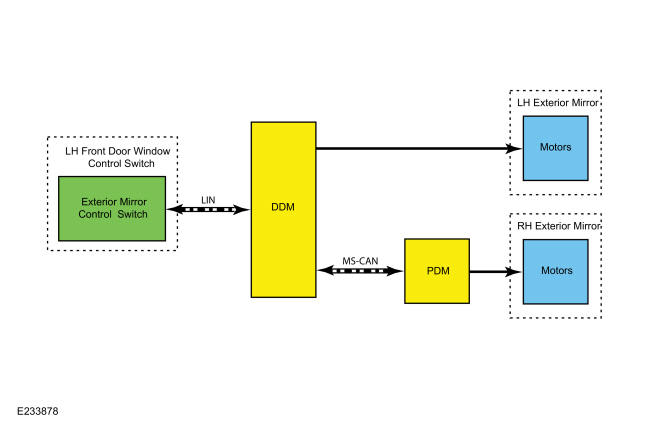
System Diagram - Exterior, Power (Without Memory)
.jpg)
| Item | Description |
|---|---|
| 1 | DDM |
| 2 | PDM |
| 3 | Motors |
| 4 | LH exterior mirror |
| 5 | Exterior mirror control switch |
| 6 | LH front door window control switch |
| 7 | Motors |
| 8 | RH exterior mirror |
Network Message Chart
Module Network Input Messages — PDM
| Broadcast Message | Originating Module | Message Purpose |
|---|---|---|
| Passenger mirror command | DDM | Contains the movement requests for the RH exterior mirror glass generated by the exterior mirror control switch. |
Rear View Mirrors - Exterior, Power (Without Memory)
All functions of the power mirror feature are integrated into one switch module (integral to the LH front door window control switch). The left and right side selection buttons have an LED to indicate which side is active and a directional pad is used for directional control. Neutral is achieved by pressing the lit button to deactivate the left or right exterior mirror, or by allowing the system to time out and reset to neutral.
When the exterior mirror directional pad switch is pressed left, right, up or down with the LH or RH exterior mirror selected, the movement request is sent to the DDM through a LIN circuit. If the LH mirror is selected, the DDM supplies voltage and ground to the appropriate LH exterior mirror motor. If the RH mirror is selected, the DDM sends the passenger mirror command message with the input from the exterior mirror control switch to the PDM. The PDM then supplies voltage and ground to the appropriate RH exterior mirror motor. The DDM and PDM controls the glass movements by reversing polarity of the voltage and ground circuits being supplied to each motor.
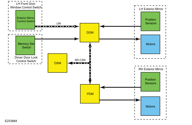
System Diagram - Exterior, Power (With Memory)
.jpg)
| Item | Description |
|---|---|
| 1 | DSM |
| 2 | DDM |
| 3 | PDM |
| 4 | Position sensors |
| 5 | Motors |
| 6 | RH exterior mirror |
| 7 | LH front door window control switch |
| 8 | Exterior mirror control switch |
| 9 | Position sensors |
| 10 | Motors |
| 11 | LH exterior mirror |
| 12 | Memory set switch |
| 13 | Driver door lock control switch |
Network Message Chart
Module Network Input Messages — DSM
| Broadcast Message | Originating Module | Message Purpose |
|---|---|---|
| Manual mirror override | DDM | Used to cancel a memory recall in the event that the exterior mirror control switch is pressed in any direction while the memory recall is taking place. |
| Memory seat switch status | DDM | Indicates the status of each memory switch button, pressed or not pressed. |
Module Network Input Messages — DDM
| Broadcast Message | Originating Module | Message Purpose |
|---|---|---|
| Memory command | DSM | Commands the door modules to initiate a memory save or recall and is used to cancel a memory recall that is in progress. |
Module Network Input Messages — PDM
| Broadcast Message | Originating Module | Message Purpose |
|---|---|---|
| Memory command | DSM | Commands the door modules to initiate a memory save or recall and is used to cancel a memory recall that is in progress. |
| Passenger mirror command | DDM | Contains the movement requests for the RH exterior mirror glass generated by the exterior mirror control switch. |
Rear View Mirrors - Exterior, Power (With Memory)
NOTE: If the DDM or PDM detects a mirror motor feedback circuit fault, a timeout strategy disables the memory operations for 30 seconds to prevent system damage. After the 30 second timeout, normal operation resumes.
All functions of the power mirror feature are integrated into one switch module (integral to the driver door window control switch). The left and right side selection buttons have a LED to indicate which mirror is active and a directional pad is used for directional control. Neutral is achieved by pressing the lit button to deactivate the left or right exterior mirror, or by allowing the system to time out and reset to neutral.
When the exterior mirror directional pad switch is pressed left, right, up or down with the LH or RH exterior mirror selected, the movement request is sent to the DDM through a LIN circuit. If the LH mirror is selected, the DDM supplies voltage and ground to the appropriate LH exterior mirror motor. If the RH mirror is selected, the DDM sends the passenger mirror command message with the input from the exterior mirror control switch to the PDM. The PDM then supplies voltage and ground to the appropriate RH exterior mirror motor. The DDM and PDM controls the glass movements by reversing polarity of the voltage and ground circuits being supplied to each motor.
When a memory recall or save is initiated, the DSM sends the memory command message to the DDM and PDM through the MS-CAN. Based on this message, the DDM and PDM recall the requested memory preset mirror position from internal memory or save the current mirror position to correspond with the requested preset. During a memory recall, the DDM and PDM supply voltage and ground to the appropriate exterior mirror motors to achieve the desired memory positions that are stored in memory based on feedback from the mirror motor potentiometers. To support the memory function, the DDM supplies a 5 volt reference and ground to the LH mirror motor potentiometers and the PDM supplies a 5 volt reference and ground to the RH mirror motor potentiometers. The DDM monitors the feedback voltage from the horizontal and vertical potentiometers to determine the position of the LH mirror glass and the PDM monitors the feedback voltage from the horizontal and vertical potentiometers to determine the position of the RH mirror glass. If the exterior mirror control switch is activated in any direction during a memory recall, the DDM sends the manual mirror override message to the DSM. After this message is received, the DSM sends the memory command message to abort the memory recall. After the recall is aborted, the DDM or PDM respond to the exterior mirror control switch inputs. A memory recall is also be aborted if the driver seat control switch is activated in any direction during a memory recall.
The LH exterior mirror glass position memory presets are stored in the DDM and the RH exterior mirror glass position memory presets are stored in the PDM.
A memory recall or memory save can be initiated by the memory set switch, a RKE transmitter, a passive entry key (if equipped) or the keyless entry keypad. For additional information on memory recall or memory save, refer to the Owner's Literature.
For additional information on the memory feature function,
Refer to: Front Seats - System Operation and Component Description (501-10A Front Seats, Description and Operation).
The DDM and PDM are capable of setting Diagnostic Trouble Codes (DTCs) for the mirror circuits.
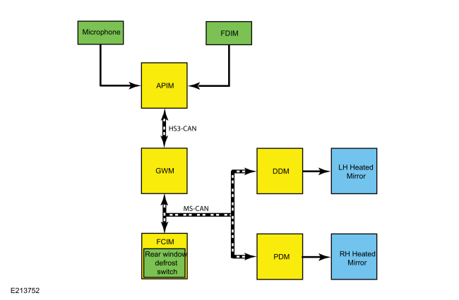
System Diagram - Exterior, Heated
.jpg)
| Item | Description |
|---|---|
| 1 | DDM |
| 2 | PDM |
| 3 | LH heated mirror |
| 4 | RH heated mirror |
| 5 | GWM |
| 6 | FDIM |
| 7 | Microphone |
| 8 | APIM |
| 9 | FCIM |
| 10 | Rear window defrost switch |
Network Message Chart
Module Network Input Messages — DDM
| Broadcast Message | Originating Module | Message Purpose |
|---|---|---|
| Mirror heat on request | FCIM | Used to command the heated exterior mirror glass on and off |
Module Network Input Messages — PDM
| Broadcast Message | Originating Module | Message Purpose |
|---|---|---|
| Mirror heat on request | FCIM | Used to command the heated exterior mirror glass on and off |
Module Network Input Messages — FCIM
| Broadcast Message | Originating Module | Message Purpose |
|---|---|---|
| Climate control requests | APIM | The climate control requests message contains the rear window defrost request information. When the rear window defrost function is requested using voice command or the button is selected on the touchscreen, this input is used to command the rear window defrost on and off. |
Rear View Mirrors - Exterior, Heated
NOTE: The DDM and PDM automatically deactivate the heated exterior mirrors when the ambient air temperature is above 30° C (86° F).
The rear window defrost system controls operation of the heated exterior mirror glass. The heated exterior mirror glass only operates when the rear window defrost system is active. The heated exterior rear view mirror glass deactivates when the rear window defrost deactivates.
The heated mirrors are heated for a period of 10 minutes when the engine is running and the defrost system is activated.
When the rear window defrost button (integral to the FCIM) is pressed, the mirror heat on request message is sent from the FCIM to the DDM and PDM over the MS-CAN. The DDM supplies voltage and ground to the LH exterior mirror heater circuits and the PDM supplies voltage and ground to the RH exterior mirror heater circuits when the exterior mirror heaters are commanded on by the FCIM.
On vehicles equipped with a LH exterior auto-dimming mirror, the LH exterior mirror glass takes longer to defrost than the RH exterior mirror glass due to differences in the mirror glass thickness.
When a concern exists, the DDM and PDM are capable of setting and storing Diagnostic Trouble Codes (DTCs) for the mirrors heater element circuits.
The rear window defrost can also be commanded on and off using voice commands or by touching the rear window defrost button located on the FDIM. For additional information on voice or touchscreen commanded features, refer to the Owner's Literature.
For additional information on the rear window defrost system,
Refer to: Glass, Frames and Mechanisms - System Operation and Component Description (501-11 Glass, Frames and Mechanisms, Description and Operation).
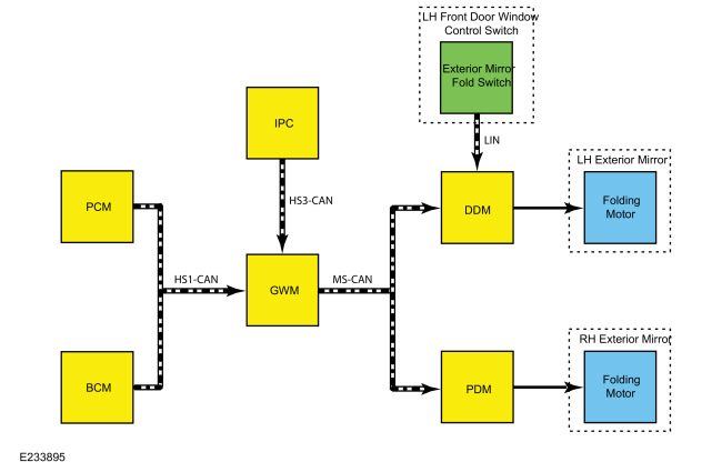
System Diagram - Exterior, Power Fold
.jpg)
| Item | Description |
|---|---|
| 1 | PCM |
| 2 | BCM |
| 3 | GWM |
| 4 | IPC |
| 5 | DDM |
| 6 | PDM |
| 7 | LH front door window control switch |
| 8 | Exterior mirror fold switch |
| 9 | Folding motor |
| 10 | LH exterior mirror |
| 11 | Folding motor |
| 12 | RH exterior mirror |
Network Message Chart
Module Network Input Messages — DDM
| Broadcast Message | Originating Module | Message Purpose |
|---|---|---|
| Gear position | PCM | Used to determine if the gear section conditions have been met to automatically fold the exterior mirrors. |
| Ignition status | BCM | Used to determine if the ignition switch conditions have been met to fold or unfold the exterior mirrors |
| Personality data | IPC | Used to turn the auto-fold mirror feature on and off based on driver input through the IPC message center. |
| Vehicle lock status | BCM | Used to determine if the vehicle locking conditions have been met to automatically fold or unfold the exterior mirrors. |
Module Network Input Messages — PDM
| Broadcast Message | Originating Module | Message Purpose |
|---|---|---|
| Passenger mirror command | DDM | When an exterior mirror fold or unfold is initiated by pressing the exterior mirror fold switch, the DDM sends the request to the PDM to control operation of the RH power folding exterior mirror. |
System Operation - Exterior, Power Fold
NOTE: If the exterior mirrors are folded and unfolded several times consecutively, the power lockout feature disables the system for approximately 3-10 minutes to prevent damage to the power fold motors. After 3-10 minutes have elapsed, normal operation resumes.
NOTE: The power folding mirrors must be synchronized anytime the LH, RH or both power folding mirrors are folded or unfolded without using the power folding mirror control switch, the automatic folding feature or if a new power folding mirror has been installed. Refer to Power Mirrors Synchronization in this section.
NOTE: If the exterior mirrors are folded by pressing the exterior mirror fold switch, the automatic folding feature is disabled until the mirrors are unfolded by pressing the exterior mirror fold switch.
NOTE: The power folding mirrors may not fold and/or unfold at the same rate of speed. This is a normal operation of the power folding mirrors.
The exterior mirrors have a power fold feature that can be activated manually or automatically (if equipped). The exterior mirrors can be manually folded and unfolded by pressing the exterior mirror fold switch (integral to the LH front door window control switch). When the automatic folding feature is turned on in the IPC message center, the exterior mirrors automatically fold in when the vehicle is locked, after the transmission is placed in park and the driver door is opened and closed. The mirrors automatically fold out when the vehicle is unlocked and the LH front door is opened and closed. The LH and RH power folding mirrors fold or unfold at the same time and cannot be controlled independently.
When the ignition is on and the exterior mirror fold switch is pressed, the fold request is sent to the DDM via the LIN. When the fold request is received, the DDM checks it's internal memory to determine the last exterior mirror fold movement that was commanded (fold or unfold). The DDM supplies voltage and ground to the LH exterior mirror folding motor and sends the passenger mirror command message to the PDM over the MS-CAN. The PDM uses this message to supply voltage and ground to the RH exterior mirror folding motor. When the exterior mirror fold switch is pressed again, the DDM reverses the polarity of the voltage supplied to the LH exterior mirror folding motor and sends the passenger mirror command message to the PDM over the MS-CAN, which reverses the polarity of the voltage supplied to the RH exterior mirror folding motor.
When the driver turns the automatic folding feature on or off in the IPC message center, the personality data message containing the selection is sent from the IPC to the DDM, with the GWM acting as a gateway. When automatic folding is turned on, the DDM monitors the ignition status and vehicle lock status messages from the BCM as well as the gear position message from the PCM. When the transmission is placed in park, the ignition is turned off, the LH front door is opened and closed and the vehicle is locked using the RKE or door switch, the DDM supplies voltage to the LH exterior mirror folding motor and sends the passenger mirror command message to the PDM over the MS-CAN, which supplies voltage to the RH exterior mirror folding motor. The exterior mirrors remain folded until the vehicle is unlocked and the LH front door is opened and closed. After the door is closed, the DDM reverses the polarity of the voltage supplied to the LH exterior mirror folding motor and sends the passenger mirror command message to the PDM over the MS-CAN, which reverses the polarity of the voltage supplied to the RH exterior mirror folding motor.
Each power fold exterior rear view mirror has an internal motor to fold or unfold the mirror that is not replaceable. If a power folding mirror drive motor is found to be inoperative, a new power folding exterior rear view mirror assembly must be installed.
System Operation - Exterior, Auto-Dimming
The LH exterior mirror auto-dimming feature automatically reduces the glare caused by bright light behind the vehicle during nighttime conditions. The interior auto-dimming mirror supplies voltage and ground to electronically darken the LH exterior mirror glass based on ambient lighting conditions. The reflectance level of the mirror glass is variable and depends on the amount of rear glare in relation to ambient light conditions in front of the interior mirror.
To provide increased visibility when backing up, the interior auto-dimming mirror glass and LH exterior mirror glass automatically returns to a high reflectance mode whenever the vehicle in REVERSE, regardless of exterior lighting conditions.
An interior auto-dimming mirror concern can affect the operation of the LH exterior mirror auto-dimming mirror.
System Operation - Interior Manual-Dimming
The manual interior rear view mirror can be adjusted from a day position to a night position to reduce unwanted glare caused by headlamps from behind the vehicle. Adjusting the interior mirror is accomplished by using the day/night tab, located on the bottom of the interior mirror. Pulling the tab rearward, towards the driver, adjusts the mirror to the night position. Pushing the tap forward, away from the driver, adjusts the mirror to the day position.
System Operation - Interior Auto-Dimming
The auto-dimming feature is active any time the ignition is ON. The interior auto-dimming mirror uses 2 integral photoelectric sensors to detect exterior lighting conditions. When the forward facing sensor detects daytime conditions, the rearward facing sensor is inactive and the mirror glass stays in a high reflectance mode. When the forward facing sensor detects nighttime conditions, the rearward facing sensor is active. When bright lights (glare) are detected by the rearward facing sensor, the mirror glass is electronically darkened. To provide increased visibility when backing up, the interior rear view mirror automatically returns to a high reflectance mode any time reverse gear is selected, regardless of exterior lighting conditions.
NOTE: NOTE: Blockage of either sensor causes false readings.
Component Description
Exterior Mirror Control Switch
The exterior mirror control switch is a momentary contact switch, integral to the LH front door window control switch, that provides the driver with the controls to move the LH and RH exterior rear view mirrors left, right, up or down. The exterior mirror control switch is connected to the DDM through a LIN circuit. The LED on each exterior mirror selection button illuminates to indicate which exterior mirror is selected for adjustment.
Exterior Mirror Fold Switch
The exterior mirror fold switch is a momentary contact switch, integral to the LH front door window control switch, that provides the driver with the controls to fold and unfold the LH and RH exterior rear view mirrors. The exterior mirror fold switch is connected to the DDM through a LIN circuit.
Memory Set Switch
The memory set switch contains 3 momentary contact switches. It is hard-wired to the DDM and is used to save or recall up to 2 memory positions. The DDM and PDM
recall the requested memory preset mirror position from internal memory
or save the current mirror position to correspond with the requested
preset. When the memory set switch (1 or 2 or SET) is activated, the DDM sends this message to the DSM
to indicate the status of each memory set switch button (pressed or not
pressed). For additional information on the memory set switch,
Refer to: Front Seats (501-10A Front Seats, Diagnosis and Testing).
Exterior Mirror
Each exterior mirror has 2 bi-directional motors that are used to control the position of the exterior mirror glass. Placing the exterior mirror control switch to the LH or RH position determines which exterior mirror motor to control.
If equipped with memory mirrors, each exterior memory mirror motor is equipped with an integral potentiometer that is monitored by the DDM ( LH mirror) or PDM ( RH mirror) to determine the position of the exterior mirror glass.
If equipped with heated mirrors, the heated exterior mirrors use heating elements that are integral to the exterior mirror glass.
If equipped with the LH exterior auto-dimming mirror, the LH exterior auto-dimming mirror glass electronically darkens when bright light is detected from behind the vehicle during nighttime conditions.
If equipped with folding mirrors, each exterior mirror has an integral bi-directional folding motor allowing the power folding mirrors to be manually (using the exterior mirror fold switch) or automatically (auto-fold feature) folded or unfolded.
The exterior mirrors include turn signals indicators. For additional information on the mirror-mounted turn signals indicators,
Refer to: Exterior Lighting - System Operation and Component Description (417-01 Exterior Lighting, Description and Operation).
The exterior mirrors include puddle lamps. For additional information on the mirror-mounted puddle lamps,
Refer to: Interior Lighting - System Operation and Component Description (417-02 Interior Lighting, Description and Operation).
The exterior mirrors may include BLIS®/ CTA Light Emitting Diodes (LEDs). For additional information on the mirror-mounted BLIS®/ CTA Light Emitting Diodes (LEDs),
Refer to: Blind Spot Information System - System Operation and Component Description (419-04 Side and Rear Vision, Description and Operation).
The exterior mirrors use a jumper harness between the vehicle wiring harness, the exterior mirror motors and the heated mirror glass. The exterior mirror jumper harness is integral to the exterior mirror. Before replacing an exterior mirror or motor, inspect the jumper harness for opens, shorted circuits or damaged and pushed-out pins. If a concern with the exterior mirror jumper harness exists, attempt to repair the jumper harness.
DDM
For the exterior mirror power functions, the DDM receives mirror movement requests through the LIN circuit from the exterior mirror control switch. When the LH exterior mirror is selected, the DDM provides voltage and ground to the appropriate LH exterior mirror motor to drive the mirror glass in the desired direction. The DDM sends RH exterior mirror movement requests to the PDM through the MS-CAN.
For the exterior power folding mirrors feature, the DDM receives mirror movement requests through the LIN circuit from the exterior mirror control switch. When a mirror fold is initiated, the DDM supplies voltage and ground to the LH exterior mirror folding motor. When the exterior mirror fold switch is utilized again, the DDM reverses the polarity of the voltage supplied to the LH exterior mirror folding motor. The DDM sends RH exterior mirror fold requests to the PDM through the MS-CAN.
For the exterior heated mirrors feature, the DDM is responsible for supplying voltage to the LH exterior mirror glass heating element based on messages received from the FCIM.
For the exterior memory mirrors feature, the DDM supplies voltage and ground to the LH mirror motor potentiometers. The DDM monitors the feedback from these potentiometers to determine the mirror glass position. Preset memory positions for the LH exterior mirror glass are stored in the DDM memory.
When a concern exists, the DDM is capable of setting and storing Diagnostic Trouble Codes (DTCs) for the LH exterior mirror motor drive circuits, position sensor circuits, heater element circuits and folding mirror motor circuits.
PMI is required if installing a new module.
PDM
For the exterior power functions, when the RH exterior mirror is selected, the PDM supplies voltage and ground to the appropriate RH exterior mirror motor to drive the mirror glass in the desired direction based on messages received from the DDM through the MS-CAN.
For the exterior power folding mirrors feature, when the PDM receives the RH exterior mirror movement requests from DDM over the MS-CAN, it provides voltage and ground to the RH exterior mirror folding motor.
For the exterior heated mirrors feature, the PDM is responsible for supplying voltage to the RH exterior mirror glass heating element based on messages received from the FCIM.
For the exterior memory mirrors feature, the PDM monitors the potentiometers in the RH exterior mirror to determine the position of the exterior mirror glass. Preset memory positions for the RH exterior mirror glass are stored in the PDM.
When a concern exists, the PDM is capable of setting and storing Diagnostic Trouble Codes (DTCs) for the RH exterior mirror motor drive circuits, position sensor circuits, folding mirror motor circuits and mirror heater circuit.
PMI is required if installing a new module.
FCIM
The FCIM contains the rear window defrost button.
PMI is required if installing a new module.
FDIM
The FDIM contains a redundant rear window defrost button on the touchscreen display. The FDIM plugs directly into the APIM, and does not communicate directly on any network.
Interior Rear View Mirror - Manual-Dimming
The manual dimming interior rear view mirror has a lever at the back of the mirror that must be pulled forward or pushed rearward by the driver to activate the manual dimming function. Manual dimming is completely controlled by the driver.
Interior Rear View Mirror - Auto-Dimming
The auto-dimming rear view mirror has 2 photoelectric sensors, one on the front of the mirror (facing the windshield) and one on the rear of the mirror (at the top of the mirror glass). Based on inputs from these sensors, the automatic dimming feature adjusts the reflectance level of the interior rear view mirror glass to eliminate unwanted glare. The reflectance level of the mirror glass is variable and depends on the amount of rear glare in relation to ambient light conditions in front of the interior mirror.
For vehicles equipped with the lane keeping system, the IPMA is integral to the interior rear view mirror. The IPMA requires PMI and camera alignment when replaced.
 Rear View Mirrors - Overview. Description and Operation
Overview
Exterior, Power
This vehicle is equipped with LH and RH
power mirrors. The power mirror system allows the exterior mirror glass
to be positioned electronically...
 Rear View Mirrors. Diagnosis and Testing
DTC Chart: DDM
Diagnostics in this manual assume a certain skill level and knowledge of Ford-specific diagnostic practices. REFER to: Diagnostic Methods (100-00 General Information, Description and Operation)...
Other information:
Ford Fusion 2013–2020 Service Manual: Parking Aid - Overview. Description and Operation
Parking Aid - Audible The rear parking aid system sounds a warning tone through the rear audio speakers to alert the driver of stationary objects near the rear bumper when reverse is selected. The parking aid system assists the driver in detecting certain objects while the vehicle moves slowly in REVERSE at speeds of less than 4...
Ford Fusion 2013–2020 Service Manual: Forward Clutch Assembly. Description and Operation
Forward (1, 2, 3, 4) Clutch Exploded View Item Description 1 Transmission case 2 Center support 3 Forward (1, 2, 3, 4) clutch piston 4 Forward (1, 2, 3, 4) clutch piston return spring 5 Forward (1, 2, 3, 4) clutch piston snap ring retainer 6 Forward (1, 2, 3, 4) clutch pis..
Categories
- Manuals Home
- 2nd Generation Ford Fusion Owners Manual
- 2nd Generation Ford Fusion Service Manual
- Garage Door Opener
- Electrical
- Pre-Collision Assist (IF EQUIPPED)
- New on site
- Most important about car
Adjusting the Steering Wheel
WARNING: Do not adjust the steering wheel when your vehicle is moving.
Note: Make sure that you are sitting in the correct position.