Ford Fusion: Uni-Body, Subframe and Mounting System / Rear Subframe - FWD. Removal and Installation
Special Tool(s) /
General Equipment
 |
300-OTC1585AE
Powertrain Lift |
| Wooden Block |
Removal
NOTICE:
Suspension fasteners are critical parts that affect the
performance of vital components and systems. Failure of these fasteners
may result in major service expense. Use the same or equivalent parts if
replacement is necessary. Do not use a replacement part of lesser
quality or substitute design. Tighten fasteners as specified.
-
On both sides. Remove the toe link.
Refer to: Toe Link (204-02 Rear Suspension, Removal and Installation).
-
On both sides. Remove the spring.
Refer to: Spring (204-02 Rear Suspension, Removal and Installation).
-
Remove the muffler and tailpipe.
Refer to: Muffler and Tailpipe (309-00B Exhaust System - 2.0L EcoBoost (184kW/250PS) – MI4, Removal and Installation).
Refer to: Muffler and Tailpipe (309-00B Exhaust System - 2.0L EcoBoost (184kW/250PS) – MI4, Removal and Installation).
-
On both sides. Remove the rear stabilizer link.
Refer to: Rear Stabilizer Bar (204-02 Rear Suspension, Removal and Installation).
-
On both sides. Remove the rear suspension height sensor.
Refer to: Rear Suspension Height Sensor (204-05 Vehicle Dynamic Suspension, Removal and Installation).
-
If equipped.
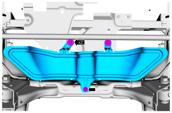
Remove the retainers and the underbody shield.
-
Remove the retainers and the underbody shields.
-
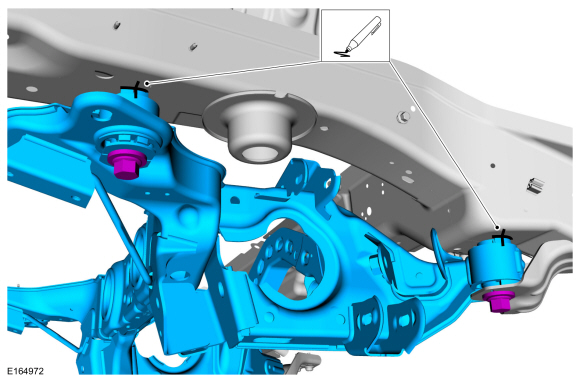
NOTE:
Index-mark the subframe for reference during installation.
On both sides.
Mark the position of the rear subframe.
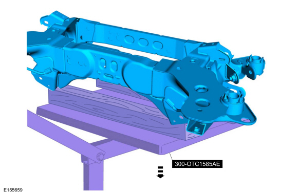
-
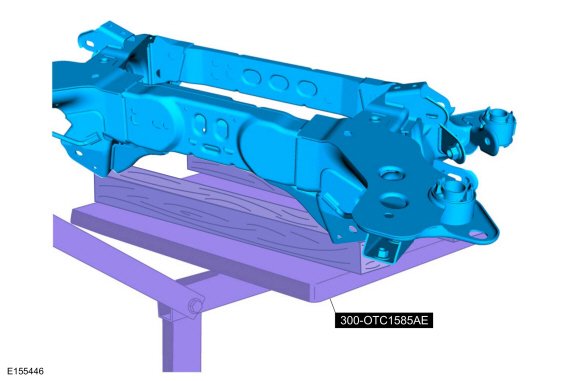
Position a powertrain lift and wooden blocks under the rear subframe.
Use Special Service Tool: 300-OTC1585AE
Powertrain Lift.
Use the General Equipment: Wooden Block
-
-
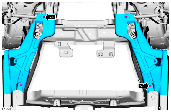
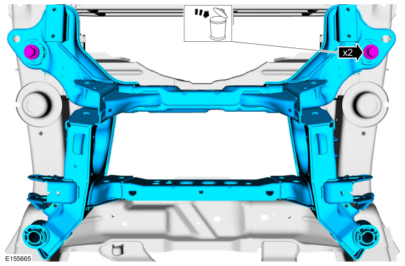
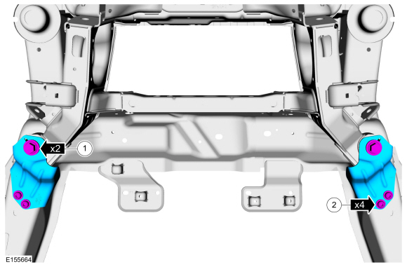
Remove and discard the rear subframe bracket bolts.
-
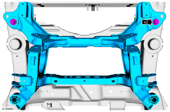
Remove and discard the rear subframe forward bolts.
-
Remove and discard the rear subframe rearward bolts.
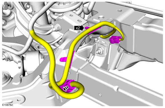
-
On both sides.
Detach the harness retainer and disconnect the electrical connectors.
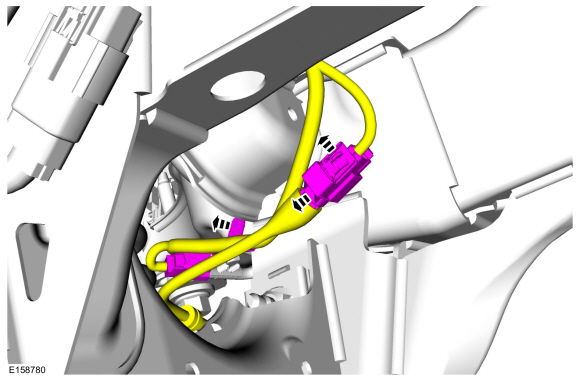
-
On both sides.
Detach the harness retainer and disconnect the electrical connector.
-
Lower the rear subframe.
Use Special Service Tool: 300-OTC1585AE
Powertrain Lift.
Use the General Equipment: Wooden Block
Installation
-
Partially raise the rear subframe and position it to the vehicle.
Use Special Service Tool: 300-OTC1585AE
Powertrain Lift.
Use the General Equipment: Wooden Block
-
On both sides.
Align the index marks made during removal.
-
-
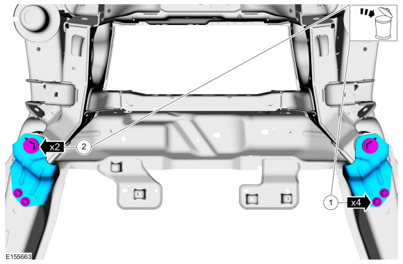
Position the brackets and install the new rear subframe forward bolts.
Torque:
129 lb.ft (175 Nm)
-
Install the bracket bolts.
Torque:
41 lb.ft (55 Nm)
-
Install the new rear subframe rearward bolts.
Torque:
129 lb.ft (175 Nm)
-
On both sides.
Attach the harness retainer and connect the electrical connectors.
-
On both sides.
Attach the harness retainer and connect the electrical connector.
-
Install the underbody shields and the retainers.
-
If equipped.
Install the underbody shield and the retainers.
-
On both sides. Install the rear suspension height sensor.
Refer to: Rear Suspension Height Sensor (204-05 Vehicle Dynamic Suspension, Removal and Installation).
-
Install the rear stabilize bar.
Refer to: Rear Stabilizer Bar (204-02 Rear Suspension, Removal and Installation).
-
Install the muffler and tailpipe.
Refer to: Muffler and Tailpipe (309-00B Exhaust System - 2.0L EcoBoost (184kW/250PS) – MI4, Removal and Installation).
Refer to: Muffler and Tailpipe (309-00B Exhaust System - 2.0L EcoBoost (184kW/250PS) – MI4, Removal and Installation).
-
On both sides. Install the spring.
Refer to: Spring (204-02 Rear Suspension, Removal and Installation).
-
On both sides. Install the toe link.
Refer to: Toe Link (204-02 Rear Suspension, Removal and Installation).
-
Calibrate the suspension system. Connect the scan tool
and carry out the Ride Height Calibration routine. Follow the scan tool
directions.
Special Tool(s) /
General Equipment
300-OTC1585AEPowertrain Lift
Tie Rod End Remover
Wooden Block
Materials
Name
Specification
Motorcraft® Threadlock 262TA-26
WSK-M2G351-A6
Removal
NOTICE:
Suspension fasteners are critical parts that affect the
performance of vital components and systems...
Special Tool(s) /
General Equipment
300-OTC1585AEPowertrain Lift
Wooden Block
Removal
NOTICE:
Suspension fasteners are critical parts that affect the
performance of vital components and systems...
Other information:
System Operation
Engine coolant flows primarily from the engine to the radiator circuit
and back to the coolant pump. Coolant is sent from the coolant pump
through the engine block and cylinder head. A separate circuit from the
engine also feeds the heater core and turbocharger with coolant...
Inspection
Cratering - fatigue failure
Spot glazing - incorrect seating
Scratching - dirty engine oil
Base exposed - poor lubrication
Both edges worn - journal damaged
One edge worn - journal tapered or bearing not seated
..


 Front Subframe - 2.7L EcoBoost (238kW/324PS). Removal and Installation
 Rear Subframe - AWD. Removal and Installation