Ford Fusion: Uni-Body, Subframe and Mounting System / Front Subframe - 2.7L EcoBoost (238kW/324PS). Removal and Installation
Special Tool(s) /
General Equipment
 |
300-OTC1585AE
Powertrain Lift |
| Tie Rod End Remover |
| Wooden Block |
Materials
| Name |
Specification |
Motorcraft® Threadlock 262
TA-26 |
WSK-M2G351-A6
|
Removal
NOTICE:
Suspension fasteners are critical parts that affect the
performance of vital components and systems. Failure of these fasteners
may result in major service expense. Use the same or equivalent parts if
replacement is necessary. Do not use a replacement part of lesser
quality or substitute design. Tighten fasteners as specified.
-
NOTICE:
Disconnect the battery ground cable anytime the
steering gear is being serviced or damage to the steering gear internal
power relay may occur resulting in steering gear replacement.
Disconnect the battery ground cable.
Refer to: Battery Disconnect and Connect (414-01 Battery, Mounting and Cables, General Procedures).
-
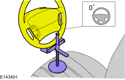
Steering wheel in straight ahead position.
-
 WARNING:
Do not reuse steering column shaft bolts. This may
result in fastener failure and steering column shaft detachment or loss
of steering control. Failure to follow this instruction may result in
serious injury to vehicle occupant(s).
WARNING:
Do not reuse steering column shaft bolts. This may
result in fastener failure and steering column shaft detachment or loss
of steering control. Failure to follow this instruction may result in
serious injury to vehicle occupant(s).
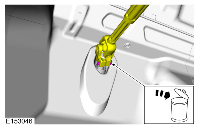
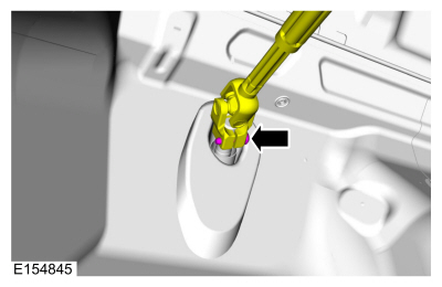
Remove and discard the steering column shaft coupler bolt and separate the coupler from the steering shaft.
-
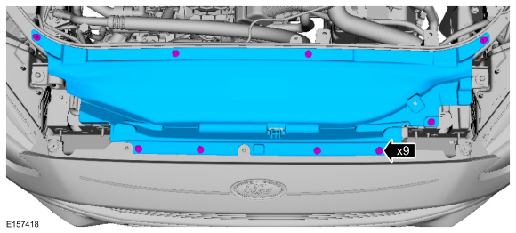
Remove the retainers and the radiator sight shield.
-
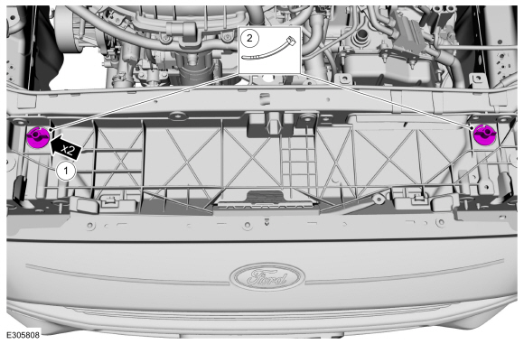
Support the cooling module.
-
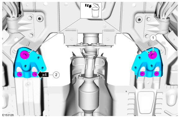
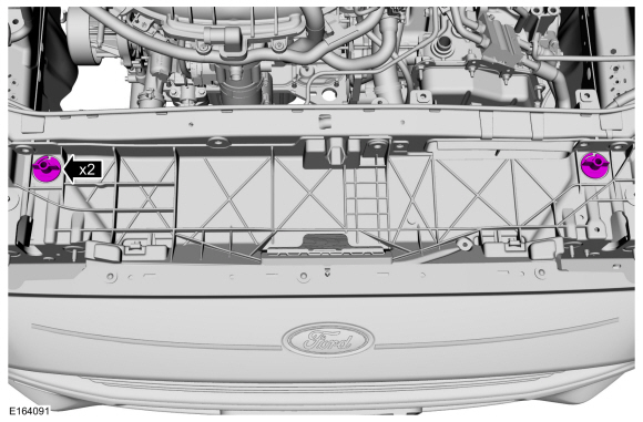
Remove the upper cooling module support brackets.
-
Using zip ties or mechanics wire through the upper location holes to support the cooling module.
-
Remove the wheels and tires.
Refer to: Wheel and Tire (204-04A Wheels and Tires, Removal and Installation).
-
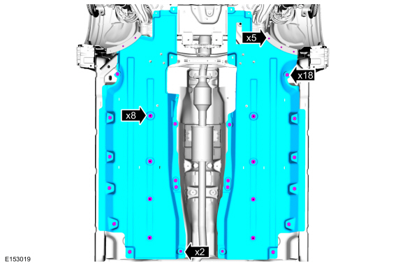
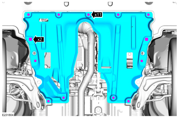
Remove the retainers and the underbody shield.
-
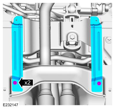
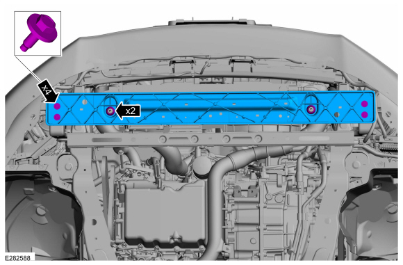
Remove the retainers and the front underbody straps.
-
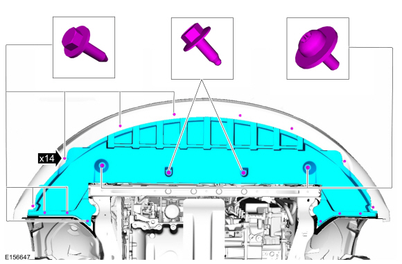
Remove the retainers and the underbody shields.
-
Remove the retainers, bolts, and underbody air deflector.
-
NOTE:
Index-mark the subframe for reference during installation.
On both sides.
Mark the position of front subframe.
-
NOTE:
Support the radiator.
Remove the retainers and remove the radiator core support.
-
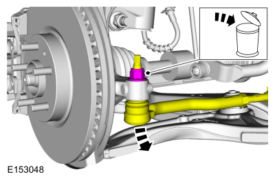
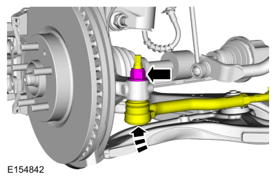
NOTICE:
Do not use a hammer to separate the outer tie-rod
end from the wheel knuckle or damage to the wheel knuckle may result.
NOTICE:
Use care when installing the tie rod separator or damage to the outer tie-rod end boot may occur.
On both sides.
Remove and discard the tie rod end nut and separate the tie rod end from the wheel knuckle.
Use the General Equipment: Tie Rod End Remover
-
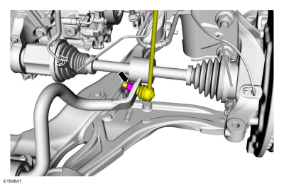
NOTE:
The stabilizer bar links are designed with low friction ball joints that have a low breakaway torque.
NOTE:
Use the hex-holding feature to prevent the ball stud
from turning while removing or installing the stabilizer bar link nut.
On both sides.
Remove and discard the stabilizer bar link lower nut and position aside the stabilizer bar link.
-
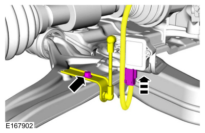
NOTICE:
The front suspension height sensor must be
disconnected from the lower control arm prior to servicing suspension
components or damage to the suspension height sensor and/or the vehicle
dynamic suspension system may occur. The sensor will need to be
recalibrated after reassembly.
On both sides.
Disconnected the front suspension height sensor
electrical connectors. Remove the bolt and position the bracket aside.
-
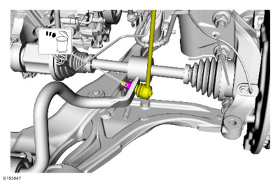
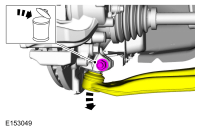
NOTICE:
Do not use a prying device or separator fork between
the ball joint and the wheel knuckle. Damage to the ball joint or ball
joint seal may result. Only use the pry bar by inserting it into the
lower arm body opening.
NOTICE:
Use care when releasing the lower arm and wheel
knuckle into the resting position or damage to the ball joint seal may
occur.
On both sides.
Remove and discard the ball joint pinch bolt and nut and separate the ball joint from the wheel knuckle.
-
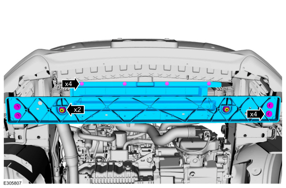
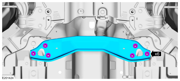
Remove the retainers and remove the cross brace.
-
Remove the exhaust flexible pipe.
Refer to: Exhaust Flexible Pipe (309-00D Exhaust System - 2.7L EcoBoost (238kW/324PS), Removal and Installation).
-
If equipped.
Remove the exhaust support bracket bolts.
-
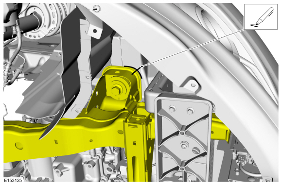
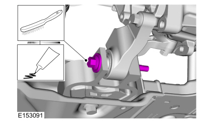
Remove the roll restrictor bolt.
-
If equipped.
Unclip and position aside the electrical harness.
-
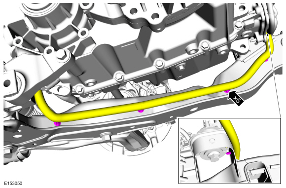
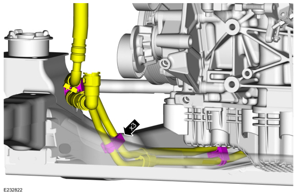
Detach the coolant tube retainers from the subframe.
-
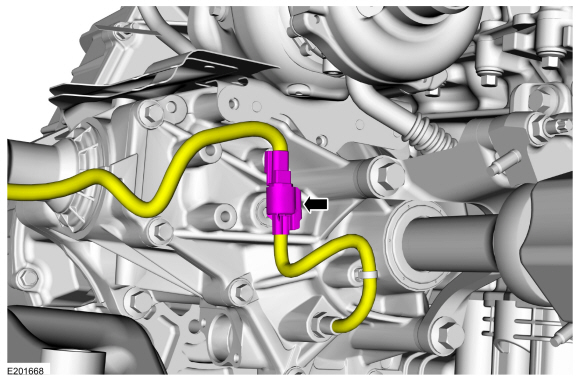
Disconnect the PTU temperature sensor.
-
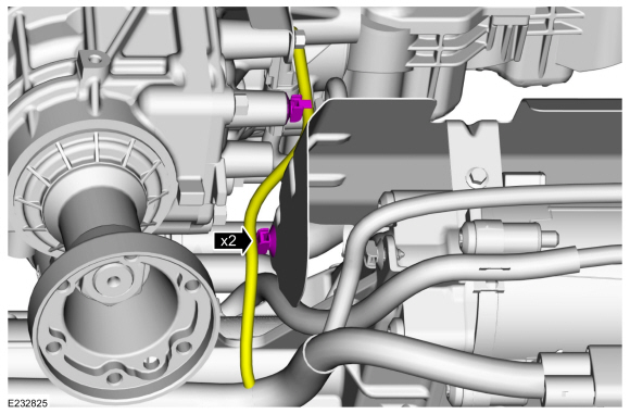
Detach the wiring harness retainers.
-
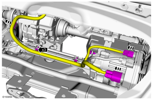
Disconnect the EPAS gear electrical connectors and unclip the harness retainers and position the harness aside.
-
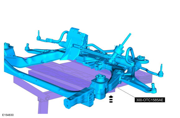
Position a powertrain lift under the front subframe.
Use Special Service Tool: 300-OTC1585AE
Powertrain Lift.
Use the General Equipment: Wooden Block
-
-
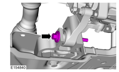
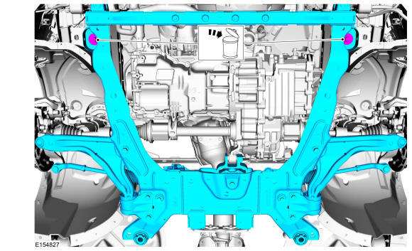
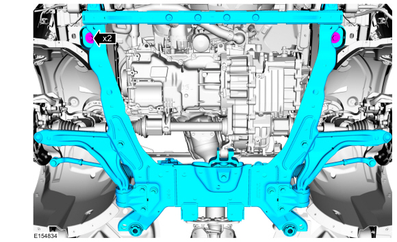
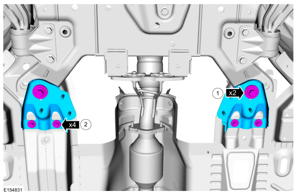
Remove and discard the rearward front subframe bolts.
-
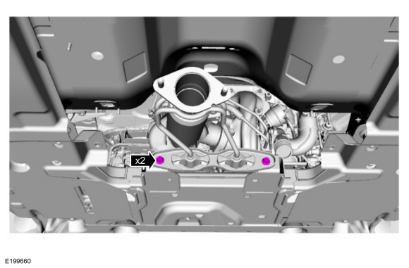
Remove the bracket bolts.
-
Remove and discard the forward front subframe bolts.
-
Lower the subframe.
Use Special Service Tool: 300-OTC1585AE
Powertrain Lift.
Use the General Equipment: Wooden Block
Installation
-
Partially raise the subframe and position it to the vehicle.
Use Special Service Tool: 300-OTC1585AE
Powertrain Lift.
Use the General Equipment: Wooden Block
-
NOTE:
Align reference marks made during removal.
Finger tight at this stage.
Install the new forward front subframe bolts.
-
-
Finger tight at this stage.
Install the new rearward front subframe bolts.
-
Finger tight at this stage.
Install the bracket bolts.
-
NOTE:
While tightening the subframe bolts, make sure the front subframe does not move.
Tighten the new forward front subframe bolts.
Torque:
173 lb.ft (235 Nm)
-
NOTE:
While tightening the subframe bolts, make sure the front subframe does not move.
-
Install the new rearward front subframe bolts.
Torque:
Stage 1:
76 lb.ft (103 Nm)
Stage 2:
270°
-
Tighten the bracket bolts.
Torque:
44 lb.ft (60 Nm)
-
Connect the PTU temperature sensor.
-
Position and clip the wiring harness retainers.
-
Position and clip the coolant tube retainers to the subframe.
-
Position the EPAS gear harness, clip the harness retainers and connect the electrical connectors.
-
Install the roll restrictor bolt.
Material: Motorcraft® Threadlock 262
/ TA-26
(WSK-M2G351-A6)
Torque:
85 lb.ft (115 Nm)
-
Install the exhaust flexible pipe.
Refer to: Exhaust Flexible Pipe (309-00D Exhaust System - 2.7L EcoBoost (238kW/324PS), Removal and Installation).
-
If equipped.
Install the exhaust support bracket bolts.
Torque:
18 lb.ft (25 Nm)
-
Install the cross brace and the retainers.
Torque:
33 lb.ft (45 Nm)
-
If equipped.
Position and clip the electrical harness.
-
Connect the lower ball joint to the wheel knuckle and install the new ball joint pinch bolt and nut.
Torque:
76 lb.ft (103 Nm)
-
On both sides.
Connected the front suspension height sensor electrical connectors. Position the bracket and install the bolt.
Torque:
177 lb.in (20 Nm)
-
NOTE:
The stabilizer bar links are designed with low friction ball joints that have a low breakaway torque.
NOTE:
Use the hex-holding feature to prevent the ball stud
from turning while removing or installing the stabilizer bar link nut.
On both sides.
Position the stabilizer bar links and install the new stabilizer bar link lower nut.
Torque:
85 lb.ft (115 Nm)
-
On both sides.
Connect the tie rod end to the wheel knuckle and install the new tie rod end nut.
Torque:
111 lb.ft (150 Nm)
-
Position the radiator core support and install the retainers.
Torque:
177 lb.in (20 Nm)
-
Install the underbody air deflector, retainers and bolts.
-
Install the front air deflectors and retainers.
-
Install the retainers and the front underbody straps.
-
Install the underbody shield and the retainers.
-
Install the wheels and tires.
Refer to: Wheel and Tire (204-04A Wheels and Tires, Removal and Installation).
-
 WARNING:
Do not reuse steering column shaft bolts. This may
result in fastener failure and steering column shaft detachment or loss
of steering control. Failure to follow this instruction may result in
serious injury to vehicle occupant(s).
WARNING:
Do not reuse steering column shaft bolts. This may
result in fastener failure and steering column shaft detachment or loss
of steering control. Failure to follow this instruction may result in
serious injury to vehicle occupant(s).
Position the steering shaft coupler and install the new steering shaft coupler bolt.
Torque:
18 lb.ft (25 Nm)
-
Install the upper radiator grommets.
-
Install the radiator sight shield and the retainers.
-
Connect the battery ground cable.
Refer to: Battery Disconnect and Connect (414-01 Battery, Mounting and Cables, General Procedures).
-
Check and if necessary adjust front toe.
Refer to: Front Toe Adjustment (204-00 Suspension System - General Information, General Procedures).
-
Calibrate the suspension system. Connect the scan tool
and carry out the Ride Height Calibration routine. Follow the scan tool
directions.
Special Tool(s) /
General Equipment
300-OTC1585AEPowertrain Lift
Tie Rod End Remover
Wooden Block
Materials
Name
Specification
Motorcraft® Threadlock 262TA-26
WSK-M2G351-A6
Removal
NOTICE:
Suspension fasteners are critical parts that affect the
performance of vital components and systems...
Special Tool(s) /
General Equipment
300-OTC1585AEPowertrain Lift
Wooden Block
Removal
NOTICE:
Suspension fasteners are critical parts that affect the
performance of vital components and systems...
Other information:
Removal
NOTE:
Removal steps in this procedure may contain installation details.
WARNING:
Before beginning any service procedure in this
section, refer to Safety Warnings in section 100-00 General Information.
Failure to follow this instruction may result in serious personal
injury...
Removal
NOTE:
Removal steps in this procedure may contain installation details.
Remove intake manifold.
Refer to: Intake Manifold (303-01A Engine - 1.5L EcoBoost (118kW/160PS) – I4, Removal and Installation).
NOTE:
The head of the KS should not touch any other component...


 Front Subframe - 1.5L EcoBoost (118kW/160PS) – I4/2.0L EcoBoost (184kW/250PS) – MI4/2.5L Duratec (125kW/170PS). Removal and Installation
 Rear Subframe - FWD. Removal and Installation