Ford Fusion: Electronic Engine Controls - 1.5L EcoBoost (118kW/160PS) – I4 / Knock Sensor (KS). Removal and Installation
Ford Fusion 2013–2020 Service Manual / Powertrain / Engine / Electronic Engine Controls - 1.5L EcoBoost (118kW/160PS) – I4 / Knock Sensor (KS). Removal and Installation
Removal
NOTE: Removal steps in this procedure may contain installation details.
-
Remove intake manifold.
Refer to: Intake Manifold (303-01A Engine - 1.5L EcoBoost (118kW/160PS) – I4, Removal and Installation).
-
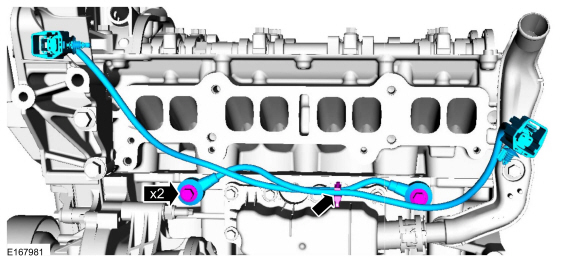
NOTE: The head of the KS should not touch any other component.
NOTE: The LH KS must be at the 10 o'clock position and the RH KS must be at the 2 o'clock position.
Remove the bolts and the KS sensors.
Torque: 159 lb.in (18 Nm)
 |
Installation
-
To install, reverse the removal procedure.
 Intake Air Temperature 2 (IAT2) Sensor. Removal and Installation
Removal
NOTE:
Removal steps in this procedure may contain installation details.
Disconnect the IAT sensor electrical connector and remove the IAT sensor...
 Manifold Absolute Pressure and Temperature (MAPT) Sensor. Removal and Installation
Removal
NOTE:
Removal steps in this procedure may contain installation details.
Remove the engine appearance cover.
Disconnect the electrical connector, remove the retainer and the MAPT sensor...
Other information:
Ford Fusion 2013–2020 Service Manual: Transmission Description - Overview. Description and Operation
Overview This automatic transmission is a 6-speed transmission with electronic shift control. It is designed for operation in a transverse powertrain for FWD and AWD vehicles. This transmission has a 4-element torque converter design, which includes a TCC and a geartrain with 3 planetary gearsets...
Ford Fusion 2013–2020 Service Manual: Hood Latch. Removal and Installation
Removal NOTE: Removal steps in this procedure may contain installation details. Remove the front bumper cover. Refer to: Front Bumper Cover (501-19 Bumpers, Removal and Installation). Left Hand (LH) Disconnect the hood ajar switch electrical connector and position aside the wiring harness...
Categories
- Manuals Home
- 2nd Generation Ford Fusion Owners Manual
- 2nd Generation Ford Fusion Service Manual
- Starter Motor. Removal and Installation
- Front Controls Interface Module (FCIM). Removal and Installation
- Body Control Module (BCM). Removal and Installation
- New on site
- Most important about car
Power Door Locks
The power door lock control is on the driver and front passenger door panels.
Copyright © 2026 www.fofusion2.com