Ford Fusion: Front Drive Halfshafts / Front Halfshaft RH. Removal and Installation
Special Tool(s) / General Equipment
 |
204-161
(T97P-1175-A)
Installer, Halfshaft TKIT-1997-LM2 TKIT-1997-F/FM2 TKIT-1997-FLM2 |
 |
205-D070
(D93P-1175-B)
Remover, Front Wheel Hub |
Removal
NOTE: FWD shown AWD is similar.
-
Remove the wheel and tire.
Refer to: Wheel and Tire (204-04A Wheels and Tires, Removal and Installation).
-
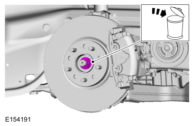
Remove and discard the halfshaft nut.
 |
-
Remove the flexible brake hose bolt and position aside the flexible brake hose.
 |
-
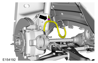
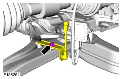
NOTICE: The front suspension height sensor must be disconnected from the lower control arm prior to servicing suspension components or damage to the suspension height sensor and/or the vehicle dynamic suspension system may occur. The sensor will need to be recalibrated after reassembly.
If equipped.
Remove the ride height sensor bolt and position aside the ride height sensor.
 |
-
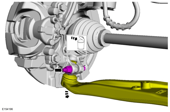
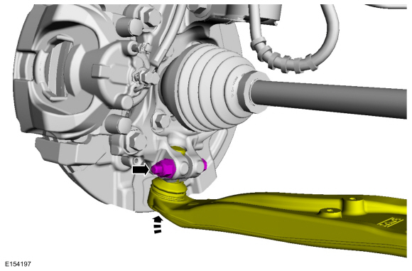
NOTICE: Do not use a prying device or separator fork between the ball joint and the wheel knuckle. Damage to the ball joint or ball joint seal may result. Only use the pry bar by inserting it into the lower arm body opening.
NOTICE: Use care when releasing the lower arm and wheel knuckle into the resting position or damage to the ball joint seal may occur.
Remove and discard the lower ball joint nut and bolt. Position the lower control arm downward.
 |
-
NOTICE: Do not bend the inner joint more than 18 degrees and the outer joint more than 45 degrees. Damage to the shaft will occur.
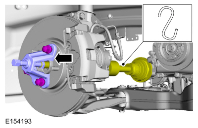
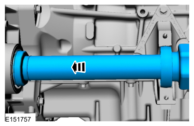
Using the special tool, press the halfshaft out from the wheel hub and bearing. Position aside and support the halfshaft.
Use Special Service Tool: 205-D070 (D93P-1175-B) Remover, Front Wheel Hub.
 |
-
If equipped.
Remove and discard the halfshaft washer.
 |
-
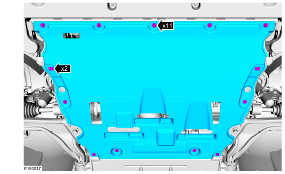
Remove the drivetrain underbody shield.
 |
-
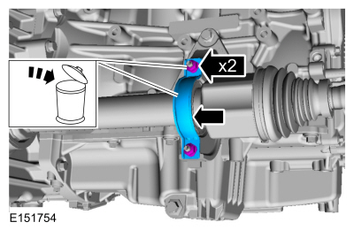
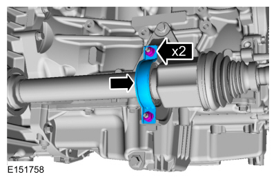
Remove and discard the halfshaft bearing bracket and halfshaft bearing bracket nuts.
 |
-
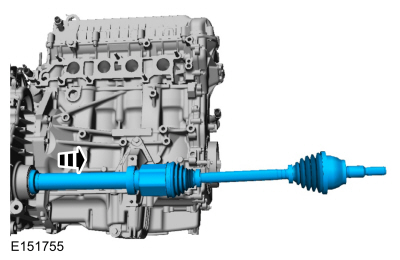
Remove the halfshaft.
 |
Installation
-
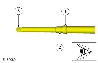
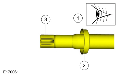
If equipped with AWD.
Inspect inboard end of the halfshaft.
 |
-
If equipped with FWD.
Inspect the inboard end of the halfshaft.
 |
-
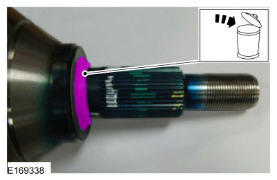
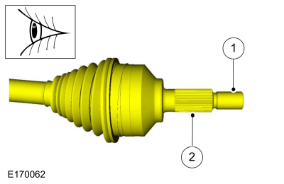
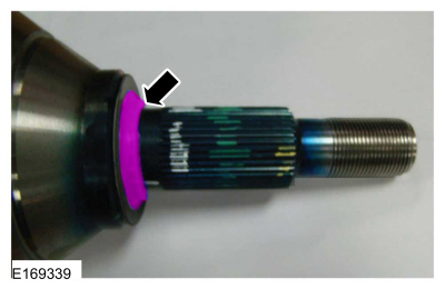
Inspect the outboard end of the halfshaft.
 |
-
If equipped with Front Wheel Drive, install a new halfshaft seal.
Refer to: Halfshaft Seal RH - FWD (307-01A Automatic Transmission - 6-Speed Automatic Transmission – 6F35, Removal and Installation).
Refer to: Halfshaft Seal RH (307-01B Automatic Transmission - 6-Speed Automatic Transmission – 6F50/6F55, Removal and Installation).
-
If equipped with All Wheel Drive, install a new intermediate shaft seal.
Refer to: Intermediate Shaft Seal (308-07B Power Transfer Unit - 6-Speed Automatic Transmission – 6F35, Removal and Installation).
Refer to: Intermediate Shaft Seal (308-07C Power Transfer Unit - 6-Speed Automatic Transmission – 6F50/6F55, Removal and Installation).
-
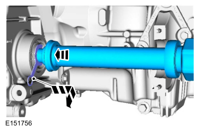
NOTE: Do not fully install the shaft at this time.
Insert the splines of the halfshaft through the halfshaft seal. Remove the seal protector.
 |
-
NOTE: Insert the halfshaft until the intermediate shaft bearing is centered in the concave groove of the intermediate shaft bearing bracket.
Install the halfshaft until the intermediate shaft bearing is centered in the intermediate shaft bearing support bracket.
 |
-
Install the new intermediate shaft bearing bracket and intermediate shaft bearing bracket nuts.
Torque:
Stage 1: Lower nut:: 44 lb.in (5 Nm)
Stage 2: Upper nut:: 18 lb.ft (25 Nm)
Stage 3: Lower nut:: 18 lb.ft (25 Nm)
 |
-
If equipped.
Install the new halfshaft washer.
 |
-
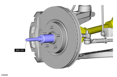
NOTE: Do not install the halfshaft any deeper than the centerline of the bearing with the centerline of the bracket. Over-installation of the halfshaft and pulling the halfshaft back out to align the bearing in the bracket could damage the intermediate shaft seal.
Using the special tool, install the halfshaft outboard end through the wheel bearing and hub assembly.
Use Special Service Tool: 204-161 (T97P-1175-A) Installer, Halfshaft.
 |
-
Install the lower ball joint into the wheel knuckle and install the new lower balljoint bolt and nut.
Torque: 76 lb.ft (103 Nm)
 |
-
If equipped.
Position the ride height sensor and install the ride height sensor bolt.
Torque: 177 lb.in (20 Nm)
 |
-
Install the flexible brake hose mounting bolt.
Torque: 159 lb.in (18 Nm)
 |
-
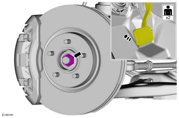
NOTICE: Do not tighten the front wheel hub nut with the vehicle on the ground. The nut must be tightened to specification before the vehicle is lowered onto the wheels. Wheel bearing damage will occur if the wheel bearing is loaded with the weight of the vehicle applied.
NOTICE: Install and tighten the new wheel hub nut to specification in a continuous rotation. Always install a new wheel hub nut after loosening or when not tightened to specification in a continuous rotation or damage to the components may occur.
NOTE: Apply the brake to keep the halfshaft from rotating.
Have an assistant apply pressure to brake pedal and install the new halfshaft nut.
Torque: 148 lb.ft (200 Nm)
 |
-
Check and top off the transmission fluid.
Refer to: Transmission Fluid Level Check (307-01A Automatic Transmission - 6-Speed Automatic Transmission – 6F35, General Procedures).
-
Install the powertrain underbody shield.
 |
-
Install the wheel and tire.
Refer to: Wheel and Tire (204-04A Wheels and Tires, Removal and Installation).
-
If equipped with dynamic suspension, calibrate the
suspension height sensor. Connect the scan tool and carry out the Ride
Height Calibration routine. Follow the scan tool directions.
 Front Halfshaft LH. Removal and Installation
Special Tool(s) /
General Equipment
204-161
(T97P-1175-A)
Installer, HalfshaftTKIT-1997-LM2TKIT-1997-F/FM2TKIT-1997-FLM2
205-D070
(D93P-1175-B)
Remover, Front Wheel Hub
Removal
Remove the wheel and tire...

Other information:
Ford Fusion 2013–2020 Service Manual: Charge Air Cooler Coolant Temperature (CACCT) Sensor. Removal and Installation
Materials Name Specification Motorcraft® Orange Prediluted Antifreeze/CoolantVC-3DIL-B WSS-M97B44-D2 Removal NOTE: Removal steps in this procedure may contain installation details. Refer to: Jacking and Lifting - Overview (100-02 Jacking and Lifting, Description and Operation). NOTE: When releasing the cooling system pressure, cover the coolant..
Ford Fusion 2013–2020 Owners Manual: Direction Indicators. Interior Lamps
Direction Indicators Push the lever up or down to use the direction indicators. Note: Tap the lever up or down to make the direction indicators flash three times to indicate a lane change. Interior Lamps The lamps turn on under the following conditions: You open any door. You press a remote control button. You press the all lamps on button on the overhead console. Front Interior Lamp ..
Categories
- Manuals Home
- 2nd Generation Ford Fusion Owners Manual
- 2nd Generation Ford Fusion Service Manual
- Powertrain
- Cylinder Head. Removal and Installation
- Intake Manifold. Removal and Installation
- New on site
- Most important about car
Power Door Locks
The power door lock control is on the driver and front passenger door panels.