Ford Fusion: Front Drive Halfshafts / Front Halfshaft LH. Removal and Installation
Special Tool(s) / General Equipment
 |
204-161
(T97P-1175-A)
Installer, Halfshaft TKIT-1997-LM2 TKIT-1997-F/FM2 TKIT-1997-FLM2 |
 |
205-D070
(D93P-1175-B)
Remover, Front Wheel Hub |
Removal
-
Remove the wheel and tire.
Refer to: Wheel and Tire (204-04A Wheels and Tires, Removal and Installation).
-
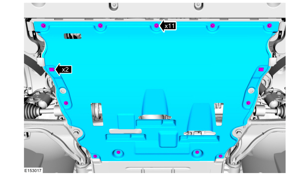
Remove the drivetrain underbody shield.
 |
-
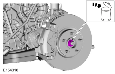
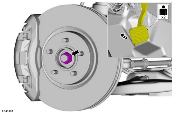
Remove and discard the wheel hub nut.
 |
-
Remove the brake hose bracket bolt and position the brake hose aside.
 |
-
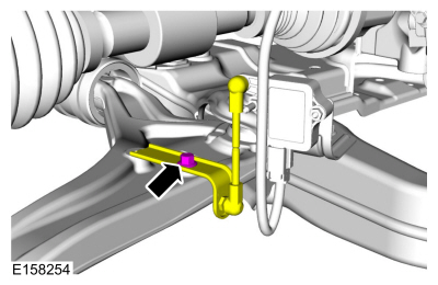
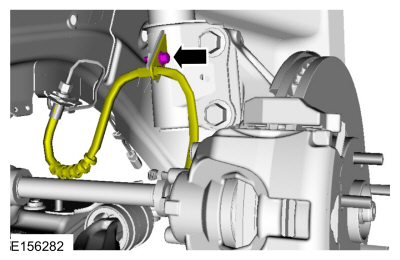
NOTICE: The front suspension height sensor must be disconnected from the lower control arm prior to servicing suspension components or damage to the suspension height sensor and/or the vehicle dynamic suspension system may occur. The sensor will need to be recalibrated after reassembly.
If equipped.
Remove the suspension height sensor bolt and position aside the suspension height sensor.
 |
-
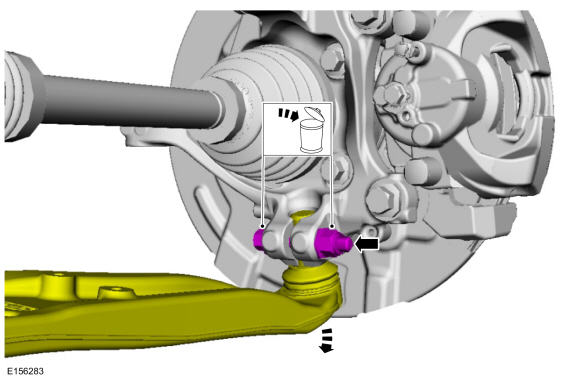
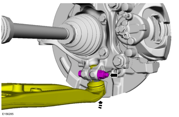
NOTICE: Do not use a prying device or separator fork between the ball joint and the wheel knuckle. Damage to the ball joint or ball joint seal may result. Only use the pry bar by inserting it into the lower arm body opening.
NOTICE: Use care when releasing the lower arm and wheel knuckle into the resting position or damage to the ball joint seal may occur.
Remove and discard the ball joint pinch bolt and nut and separate the ball joint from the wheel knuckle.
 |
-
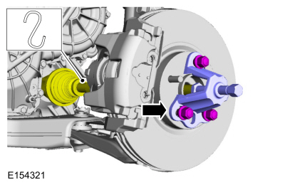
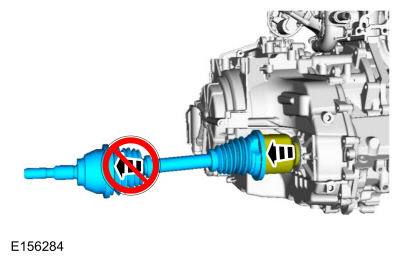
NOTICE: Do not bend the inner joint more than 18 degrees and the outer joint more than 45 degrees. Damage to the shaft will occur.
Install the special tool and press the halfshaft from the front wheel bearing and wheel hub.
Use Special Service Tool: 205-D070 (D93P-1175-B) Remover, Front Wheel Hub.
 |
-
If equipped.
Remove and discard the halfshaft washer.
 |
-
NOTE: Do not pull on the halfshaft. Pull or pry on the inner CV housing only or damage may occur.
Remove the halfshaft.
 |
-
Remove and discard the halfshaft retaining circlip.
 |
Installation
-
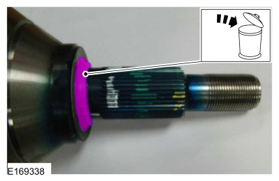
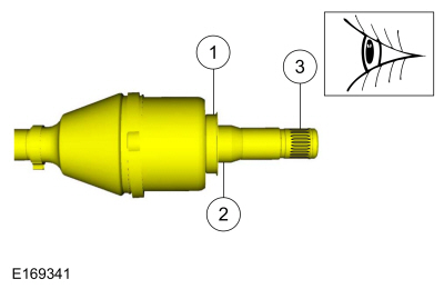
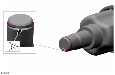
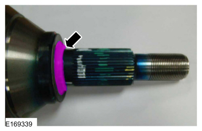
Inspect the outer CV housing at the shown locations.
 |
-
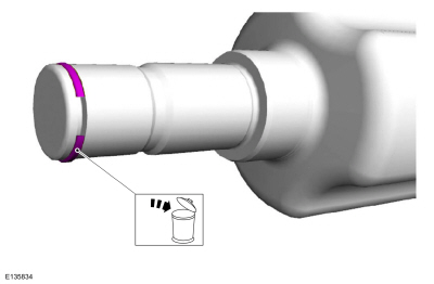
Inspect the inner CV housing at the shown locations.
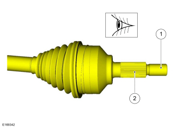 |
-
NOTE: Make sure new component is installed.
Install the new inner halfshaft retaining circlip.
 |
-
Install a new halfshaft seal.
Refer to: Halfshaft Seal LH (307-01A Automatic Transmission - 6-Speed Automatic Transmission – 6F35, Removal and Installation).
Refer to: Halfshaft Seal LH (307-01B Automatic Transmission - 6-Speed Automatic Transmission – 6F50/6F55, Removal and Installation).
-
NOTE: Do not fully install shaft at this time.
Using the seal protector, insert the splines of the halfshaft through the halfshaft seal. Remove the seal protector.
 |
-
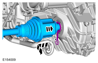
NOTE: Insert shaft until circlip is fully seated. When checking if circlip is seated do not pull on CV joints or damage can result.
NOTE: Pull on the inner CV joint to ensure the halfshaft circlip is seated properly.
Insert the halfshaft until the halfshaft retaining clip is fully seated.
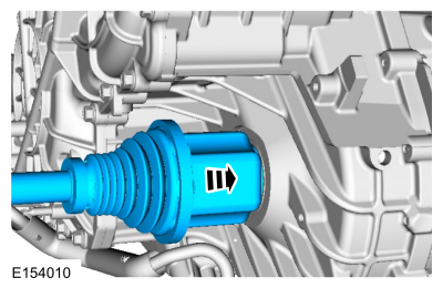 |
-
If equipped.
Install a new halfshaft washer.
 |
-
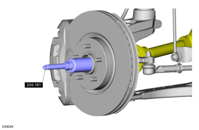
Pull the halfshaft into the front wheel bearing and wheel hub.
Use Special Service Tool: 204-161 (T97P-1175-A) Installer, Halfshaft.
 |
-
Position the ball joint into the wheel knuckle and install the new ball joint pinch bolt and nut.
Torque: 76 lb.ft (103 Nm)
 |
-
If equipped.
Position back the suspension height sensor and install the bolt.
Torque: 177 lb.in (20 Nm)
 |
-
Position the brake hose and install the brake hose bracket bolt.
Torque: 159 lb.in (18 Nm)
 |
-
NOTICE: Do not tighten the front wheel hub nut with the vehicle on the ground. The nut must be tightened to specification before the vehicle is lowered onto the wheels. Wheel bearing damage will occur if the wheel bearing is loaded with the weight of the vehicle applied.
NOTICE: Install and tighten the new wheel hub nut to specification in a continuous rotation. Always install a new wheel hub nut after loosening or when not tightened to specification in a continuous rotation or damage to the components may occur.
NOTE: Apply the brake to keep the halfshaft from rotating.
Install the wheel hub nut. While an assistant applies the brake, tighten the new wheel hub nut.
Torque: 148 lb.ft (200 Nm)
 |
-
Check the transmission fluid level.
Refer to: Transmission Fluid Drain and Refill (307-01A Automatic Transmission - 6-Speed Automatic Transmission – 6F35, General Procedures).
Refer to: Transmission Fluid Level Check (307-01B Automatic Transmission - 6-Speed Automatic Transmission – 6F50/6F55, General Procedures).
-
Install the powertrain underbody shield.
 |
-
Install the wheel and tire.
Refer to: Wheel and Tire (204-04A Wheels and Tires, Removal and Installation).
-
If equipped with dynamic suspension, calibrate the
suspension height sensor. Connect the scan tool and carry out the Ride
Height Calibration routine. Follow the scan tool directions.
 Front Drive Halfshafts. Diagnosis and Testing
Preliminary Inspection
Visually inspect the CV joints, housing, boots, and clamps for obvious signs of mechanical damage.
If an obvious cause for an observed or reported concern is
found, correct the cause (if possible) before proceeding to the next
step
If the cause is not visually evident, verify the symptom and REFER to Symptom Chart: NVH...
 Front Halfshaft RH. Removal and Installation
Special Tool(s) /
General Equipment
204-161
(T97P-1175-A)
Installer, HalfshaftTKIT-1997-LM2TKIT-1997-F/FM2TKIT-1997-FLM2
205-D070
(D93P-1175-B)
Remover, Front Wheel Hub
Removal
NOTE:
FWD shown AWD is similar...
Other information:
Ford Fusion 2013–2020 Service Manual: Message Center - System Operation and Component Description. Description and Operation
System Operation System Diagram Item Description 1 PCM 2 Message center display 3 LH upper steering wheel switch 4 ABS module 5 PSCM 6 OCSM 7 IPC 8 BCM 9 Door ajar switches 10 Parking brake switch 11 Brake fluid level switch 12 GWM 13 Washer fluid level switch 14 S..
Ford Fusion 2013–2020 Service Manual: Transmission Range Control Module (TRCM). Removal and Installation
Removal With the vehicle in N, position it on a hoist. Refer to: Jacking and Lifting - Overview (100-02 Jacking and Lifting, Description and Operation). NOTE: When installing a new TRCM, it is necessary to initiate "Default to Park". Perform the following steps to initiate "Default to Park". Remove the RH fender splash shield. Refer to: Fender Splash Shield (501-02..
Categories
- Manuals Home
- 2nd Generation Ford Fusion Owners Manual
- 2nd Generation Ford Fusion Service Manual
- Pre-Collision Assist (IF EQUIPPED)
- Starter Motor. Removal and Installation
- Main Control Valve Body. Removal and Installation
- New on site
- Most important about car
Understanding Your Tire Pressure Monitoring System
The tire pressure monitoring system measures pressure in your road tires and sends the tire pressure readings to your vehicle. You can view the tire pressure readings through the information display. The low tire pressure warning light will turn on if the tire pressure is significantly low. Once the light is illuminated, your tires are under-inflated and need to be inflated to the manufacturer’s recommended tire pressure. Even if the light turns on and a short time later turns off, your tire pressure still needs to be checked.