Ford Fusion: Instrumentation, Message Center and Warning Chimes / Message Center - System Operation and Component Description. Description and Operation
System Operation
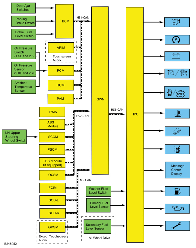
System Diagram
.jpg)
| Item | Description |
|---|---|
| 1 | PCM |
| 2 | Message center display |
| 3 | LH upper steering wheel switch |
| 4 | ABS module |
| 5 | PSCM |
| 6 | OCSM |
| 7 | IPC |
| 8 | BCM |
| 9 | Door ajar switches |
| 10 | Parking brake switch |
| 11 | Brake fluid level switch |
| 12 | GWM |
| 13 | Washer fluid level switch |
| 14 | SODR |
| 15 | Primary fuel level sensor |
| 16 | IPMA |
| 17 | HCM |
| 18 | PAM |
| 19 | Oil pressure sensor (2.0L and 2.7L) |
| 20 | FCIM |
| 21 | SODL |
| 22 | SCCM |
| 23 | Secondary fuel level sensor |
| 24 | All wheel drive |
| 25 | Ambient temperatue sensor |
| 26 | Tracking and Blocking System (TBS) module (if equipped) |
| 27 | GPSM |
| 28 | Except touchscreen audio |
| 29 | APIM |
| 30 | Touchscreen audio |
| 31 | Oil pressure switch (1.5L and 2.5L) |
Network Message Chart
Module Network Input Messages - IPC
| Broadcast Message | Originating Module | Message Purpose |
|---|---|---|
| Autopark status | PAM | Input used to control the parking aid messages displayed in the message center. |
| AWD service required | PCM | Input used for the AWD component to control the powertrain malfunction (wrench) RTT indicator. |
| AWD locking status | PCM | Input used to display the AWD messages. |
| Body service required request | BCM | Input used for the BCM controlled system faults input to control the powertrain malfunction (wrench) RTT indicator. |
| Brake fluid level low message request | BCM | Input used to display the message center brake system messages. |
| Brake pedal applied | PCM | Input used to display the not in park warning message. |
| Brake warning indicator request | ABS module | Input used to display the electric parking brake message center warning messages. |
| Brake (red) warning indicator request | ABS module | Input used to display the message center brake system messages. Also used to display the electric parking brake message center warning messages. |
| Charging system indication request | BCM | Input used to control the charging system and load shed message center warning indicator and warning messages. |
| Check fuel fill inlet message request | PCM | Input used to display the check fuel fill inlet message. |
| Child lock message display request | BCM | Input used to display the child lock system fault message. |
| Compass direction (touchscreen audio) | APIM | Input used to provide the compass display. |
| Cross traffic alert left status | SODL | Input used to control the blind spot information system RTT indicator. |
| Cross traffic alert right status | SODR | Input used to control the blind spot information system RTT indicator. |
| Cruise control set speed | PCM | Input used to control the cruise control set speed displayed in the message center. |
| Cruise control status | PCM | Input used to control the cruise control RTT indicator and message display based on the system status. |
| Cruise control override | PCM | Input used to control the adaptive cruise control set speed display when the cruise control is overridden by the driver. |
| Door ajar status | BCM | Input used to control the door ajar RTT indicator. |
| Driver door ajar status | BCM | Input used to display the not in park warning message. |
| EPAS failure | PSCM | Input used to control the service power steering message display. |
| Engine coolant temperature data | PCM | Input used to control the temperature gauge and the over-temperature RTT indicator. |
| Engine oil life | PCM | Input used for the oil life display. |
| Engine oil life reset | PCM | Input used to confirm oil life reset. |
| Engine overheat indication request | PCM | Input used to control the temperature gauge and the over-temperature RTT indicator. |
| Engine rpm data | PCM | Input used to control the low oil pressure message center warning indicator and the DTE display. |
| Engine service required request | PCM | Input used for the powertrain Electronic Throttle Control (ETC) component to control the powertrain malfunction (wrench) RTT indicator. |
| Forward collision warning message request | CCM | Input used to control the forward collision popup and warning message display. |
| Fuel maintenance mode display | PCM | Input used to display the fuel maintenance mode message. |
| GPS compass direction (except touchscreen audio) | GPSM | Input used to provide the compass display. |
| Gear lever position | PCM | Input used to display the active park assist messages. |
| GSM service required | GSM | Input used to display the GSM fault message. |
| Ignition key type | BCM | Input used to calculate the Average Fuel Economy (AFE) and DTE for MyKey® settings. |
| Ignition status | BCM | Ignition RUN, START and accessory states required for the IPC operating modes and fault reporting. Also used to display the not in park warning message. |
| Intelligent Access (IA) system message display | BCM | Input used to display the Intelligent Access (IA) no key detected, place key in backup slot and accessory power active message center warning displays. |
| Lane departure warning indicator request | IPMA | Input used to control the lane departure warning system indicator. |
| Lane departure warning system status display | IPMA | Input used to control the display of lane departure warning system message center warning messages. |
| Life cycle mode | BCM | Input used to indicate whether the vehicle is set in factory mode or transport mode to display the appropriate message and power down items such as the PRNDL at key off to conserve the battery. |
| Object entrapped message | OCSM | Input used to display the remove objects near the passenger seat warning message. |
| Odometer count | PCM |
|
| Oil pressure warning indicator request | PCM | Input used to control the low oil pressure message center warning indicator. |
| Parking aid status | PAM | Input used to display the active park assist messages. |
| Parking brake status | ABS module | Input used to display the message center brake system messages. Also used for the display of the electric parking brake message center warning messages. |
| Perimeter alarm chime request | BCM | Input used to display the perimeter alarm message when the vehicle is entered before deactivating the perimeter alarm. |
| Powertrain cooling message request | PCM | Input used to display the reduced power to cool the engine on the Gasoline Turbo Direct Injection (GTDI) engines. |
| Remote start status | BCM | Input used to control the remote start active message display. |
| Reverse gear state | PCM | Input used to display the active park assist messages. |
| Starting system fault message request | PCM | Input used to display starting system messages. |
| Stability-traction control chime request | ABS module | Input used to control the service AdvanceTrac® and traction control off warning displays. Also used to control the traction control on/off status messages. |
| Stability-traction control disabled indicator request | ABS module | Input used to control the traction control on/off status messages. |
| Steering wheel lock message request | BCM | Input used to control the steering wheel lock system messages. |
| Stop/start message request | PCM | Input used to control the auto stop/start message display. |
| Tracking and blocking indication request | Tracking and Blocking System (TBS) module | Input used to display the tracking and blocking malfunction message. |
| Transmission fault message request | PCM | Input used to display the transmission over-temperature and fault messages. |
| Transmission gear display actual | PCM | Input used to display the not in park warning message. |
| Transmission service required | PCM | Input used for the transmission component to control the powertrain malfunction (wrench) RTT indicator. |
| Transmission shift indicator | PCM | Input used to control the upshift RTT indicator. |
| Transmission shift mode request | ABS module | Input used to control the grade assist indicator. |
| Vehicle dynamics SOS | ABS module | Input used to control the spin-out detected message. |
| Vehicle speed | PCM | Input used to display the not in park warning message and used to calculate the Average Fuel Economy (AFE) and DTE. |
Message Center Displays
Compass Display (Except Touchscreen Audio)
On the base and mid-level IPC, the compass is displayed as a 1 or 2 character display in the message center that indicates the current direction of the vehicle (N, NE, E, SE, S, SW, W, or NW). On the high-level IPC, the compass can be displayed as a virtual compass along with the 1 or 2 character display. The IPC receives the GPS compass direction from the GWM over the HS-CAN3. The GWM receives the GPS compass direction from the GPSM over the MS-CAN.
Compass Display (Touchscreen Audio)
On the base and mid-level IPC, the compass is displayed as a 1 or 2 character display in the message center that indicates the current direction of the vehicle (N, NE, E, SE, S, SW, W, or NW). On the high-level IPC, the compass can be displayed as a virtual compass along with the 1 or 2 character display. The IPC receives the compass direction message from the GWM over the HS-CAN3. The GWM receives the compass direction message from the APIM over the HS-CAN1.
DTE/Average Fuel Economy (AFE)
The DTE is calculated in the IPC using the Running Average Fuel Economy (RAFE), which is the fuel economy over the last 480 km (300 miles), and the fuel level input from the fuel sender(s) to determine how many kilometers the vehicle can be driven based on the remaining fuel in the tank. The DTE can vary in the short term by up to 80 km (50 miles), but is usually within 16 km (10 miles). Even if the fuel economy is relatively constant, the DTE can be off over a 80 km (50 mile) range by -24% to +38%. The DTE display and the fuel gauge both use the fuel level input from the fuel tank to provide their respective functions. If the fuel gauge doesn't function correctly, both the fuel gauge and the DTE display are affected.
The IPC defaults to a preset baseline mpg when the battery is initially connected and changes based on driving habits and conditions.
NOTE: The actual DTE can be higher or lower than the DTE displayed in the message center due to changes in driving conditions. It is important to understand how the DTE is calculated and the factors that impact the DTE display when determining how to address any DTE concerns.
Since the DTE is calculated and averaged over a longer period of time (480 km [300 miles]), varying driving conditions can have a significant impact on the current or short term DTE as opposed to the displayed DTE. This difference often leads to customer complaints of incorrect or invalid DTE. The following list provides some (not all) of the driving conditions that may lead to an incorrect or fluctuating DTE concern:
- Changing between towing/not towing
- Changing driving between city and highway
- Allowing the vehicle to idle for long periods of time
- Using the remote start feature frequently to allow the vehicle to warm up, particularly when parked on a grade
- Parking or driving on grades
- Inconsistent use of gasoline or E85 fuels
- Over-fueling or not filling the tank completely (partial refueling)
The IPC uses the following network messages to control the DTE/Average Fuel Economy (AFE).
- Fuel flow volume display
- Odometer count
- Transport mode
The IPC receives all messages from the GWM over the HS-CAN3. The GWM receives the transport mode message from the BCM over the HS-CAN1 and the fuel alcohol percent, fuel flow volume display and the odometer count messages from the PCM over the HS-CAN1.
Factory-Transport Mode
During vehicle build, some modules, such as the IPC and the BCM, are set in factory mode. While in the factory mode the IPC displays FACTORY MODE CONTACT DEALER in the message center. If the vehicle is set in factory mode, the system does not automatically exit the mode and must be manually set to either the transport or normal operation mode.
When the vehicle build is complete, the vehicle is set to transport mode. While in transport mode, the IPC displays TRANSPORT MODE CONTACT DEALER in the message center. Transport mode is used to reduce the drain on the battery during longer periods where the vehicle is not used. Various systems may be altered or are disabled when in the transport mode. The vehicle automatically reverts to normal operation mode after being driven 80 km (50 mi).
The IPC receives the life cycle mode message from the GWM over the HS-CAN3. The GWM receives the life cycle mode message from the BCM over the HS-CAN1.
Forward Collision
The message center provides a popup and warning message display to inform the driver of a pre-collision event. The IPC receives the forward collision warning message request from the GWM over the HS-CAN3. The GWM receives the forward collision warning message request from the CCM over the HS-CAN2.
Lane Keeping System
The lane departure warning system combines the lane keeping alert and lane keeping aid systems. The lane keeping alert system alerts the driver of unintentional drifting outside of the lane and the lane keeping aid system corrects the vehicle steering to keep the vehicle in the center of the lane. The IPC provides a lane departure warning display as an overhead view of the vehicle in the middle of a lane with right and left lane markers to indicate the vehicle position with relation to the lane markings as well as overlay or popup messages to alert the driver when they are drifting out of their lane. The lane markers change color to indicate the condition associated with a specific condition and action or warning as controlled by the lane departure warning system. The IPC also provides a lane departure warning system message center off indicator to inform the driver that the lane departure warning system is turned off. When the lane departure warning system is turned off, the IPC turns on the lane departure warning system RTT indicator and turns off the lane departure warning system display.
The IPC receives both the lane departure warning system status display message and the lane departure warning indicator request from the GWM over the HS-CAN3.
The GWM receives the lane departure warning system status display message and the lane departure warning indicator request from the IPMA over the HS-CAN2.
MyKey® Function
The IPC provides message center displays for the MyKey® feature. MyKey® displays are controlled through the IPC software based on the MyKey® settings configured through the message center and the type of key in use (MyKey® or administrator key). The MyKey® function also uses other messages received by the IPC for other indications such as vehicle speed for speed limiter displays.
Odometer
The IPC receives the odometer count message from the GWM over the HS-CAN3. The GWM receives the odometer count from the PCM over the HS-CAN1. The IPC monitors the odometer count input from the GWM and commands the odometer with a digital display in the message center.
Oil Life
The IPC provides message center messages to inform the driver about the oil life status and when an oil change is required. The duration of the interval between oil changes is calculated in the PCM and varies due to driving conditions. The PCM assumes a base mileage of 16,090 km (10,000 mi) or 1 year for normal driving. However, this number is adjusted down for conditions such as high engine temperature, high engine rpm, use of flex fuel and possibly low oil level. The PCM calculates and provides the engine oil life percent message to the IPC. The IPC further converts the remaining oil life using the driver's configured oil life start value and displays the oil life percentage, indicating the remaining oil life. The oil change minder can be reset at any time by the driver.
The IPC receives the engine oil life message and engine oil life reset request from the GWM over the HS-CAN3.
The PCM receives the engine oil life reset request from the GWM over the HS-CAN3.
The GWM receives the engine oil life message from the PCM over the HS-CAN1.
The GWM receives the engine oil life reset message from the IPC over the HS-CAN1.
Outside Air Temperature
The Ambient Air Temperature (AAT) sensor is hardwired to the PCM through separate input and return circuits. The PCM provides a reference voltage to the Ambient Air Temperature (AAT) sensor and monitors the change in voltage resulting from changes in resistance as determined by outside air temperature. The PCM sends the ambient air temperature message to the GWM through the HS-CAN1. The GWM sends the ambient air temperature to the FCIM over the MS-CAN. The FCIM filters the data and sends the ambient air temperature filtered message to the IPC through the GWM over the HS-CAN3.
The FCIM updates the messaged outside temperature data at different rates depending on several criteria to prevent false temperature displays due to a condition known as heat soaking. Heat soaking is where the outside air temperature is hotter in the location of the Ambient Air Temperature (AAT) sensor than the actual outside air temperature.
When the sensed outside temperature rises, the display updates slowly at varying rates based on vehicle speed. When the sensed outside temperature drops, the display updates more quickly following the drop experienced by the Ambient Air Temperature (AAT) sensor.
When the sensed outside temperature rises, the display updates slowly at varying rates based on vehicle speed. When the sensed outside temperature drops, the display updates more quickly following the drop experienced by the Ambient Air Temperature (AAT) sensor.
RTT Indicators
Auto Stop-Start
The IPC provides the auto stop-start RTT indicator to inform the driver of the system status. The IPC receives the stop/start message request from the GWM over the HS-CAN3. The GWM receives the stop/start message request from the PCM over the HS-CAN1.
Charging System
The IPC provides a charging system RTT indicator to indicate a fault in the charging system. When a fault is present in the charging system, the BCM sends the charging system indication request to display message center warning messages and the charging system message center warning indicator.
The IPC receives the charging system indication request message from the GWM over the HS-CAN3. The GWM receives the charging system indication request message from the BCM over the HS-CAN1.
Cruise Control
The IPC uses the following messaged inputs to control the cruise control RTT indicator:
- cruise control status
- cruise control set speed
- cruise control override
The IPC uses cruise control status, cruise control set speed and cruise control override messaged inputs to control the cruise control RTT indicator. When the ECO mode is active, the cruise control system allows a wider range of vehicle speed loss before accelerating to maintain the selected speed for better economy. The IPC receives the cruise control messages from the GWM over the HS-CAN3. The GWM receives the cruise control messages from the PCM over the HS-CAN1.
Door Ajar
The IPC provides a door ajar RTT indicator to indicate the status of the doors or luggage compartment lid. The BCM monitors each of the ajar inputs and sends a door ajar status message to the GWM over the HS-CAN1. The IPC receives the door ajar status message from the GWM over the HS-CAN3 to display the specific ajar message center warning indicator and corresponding warning message.
Engine Over-Temperature
The IPC provides a RTT warning indicator to alert the driver the engine is over temperature. The IPC receives the engine overheat indication request and the engine coolant temperature data from the GWM over the HS-CAN3. The GWM receives the engine overheat indication request and the engine over-temperature message from the PCM over the HS-CAN1.
Grade Assist
The grade assist RTT indicator informs the driver the grade assist function is turned on and is in ready mode. The IPC receives the transmission shift mode request message from the GWM over the HS-CAN3. The GWM receives the transmission shift mode request message from the PCM over the HS-CAN1.
Low Fuel
To supplement the fuel gauge indication, the IPC provides the low fuel message center warning indicator. When the DTE reaches less than approximately 50 km (30 miles) DTE (without MyKey® key) or 80 km (50 miles) DTE (with MyKey® key), the IPC turns on the low fuel message center warning indicator.
Low Oil Pressure
The engine oil pressure switch is hardwired to the PCM. The PCM provides the engine oil pressure indicator request and engine rpm data to the GWM over the HS-CAN1. The IPC receives the oil pressure warning indicator request and engine rpm data from the GWM over the HS-CAN3. The IPC requires engine rpm above 400 rpm before the message center displays the low oil pressure RTT indicator.
Powertrain Malfunction (Wrench)
The IPC provides a powertrain malfunction (wrench) RTT indicator to indicate transmission, Electronic Throttle Control (ETC), AWD, and BCM concerns.
The IPC receives all the required messages from the GWM over the HS-CAN3.
The GWM receives the body service required message from the BCM over the HS-CAN1.
The GWM receives the transmission service required, engine service required and AWD service required messages from the PCM over the HS-CAN1.
Warning Messages
AWD
The IPC provides message center messages to inform the driver of the status of the AWD. The IPC receives the AWD locking status message from the GWM over the HS-CAN3. The GWM receives the AWD locking status message from the PCM over the HS-CAN1.
Auto Stop-Start
The IPC provides the auto stop-start message displays to provide direction related to the driver intervention required at various times throughout the auto stop-start system operation and to provide the driver with the system status. The IPC receives the stop/start message request from the GWM over the HS-CAN3. The GWM receives the stop/start message request from the PCM over the HS-CAN1.
Blind Spot Monitoring System (BLIS) Off
The IPC provides a RTT indicator to inform the driver that the Blind Spot Monitoring System (BLIS) is turned off. The IPC receives the cross traffic alert left status and cross traffic alert right status messages from the SODL and SODR through the GWM over the HS-CAN3.
Brake System
The IPC provides brake system indicators for the following concerns and status:
- Low brake fluid level
- Parking brake status and faults
- ABS concerns that display along with the brake warning indicator operation
When the parking brake is applied, the BCM sends the parking brake status to the GWM over the HS-CAN1. The GWM gateways the message to the IPC over the HS-CAN3 to illuminate the brake warning indicator and turn on the parking brake applied message in the message center.
When a low brake fluid level condition exists, the BCM sends the brake fluid level low message request to the GWM over the HS-CAN1. The GWM gateways the message to the IPC over the HS-CAN3 to illuminate the brake warning indicator and turn on the brake fluid level low message in the message center.
When an ABS or parking brake system concern exists, the ABS module sends the brake (red) warning indicator request message to the GWM over the HS-CAN2. The GWM sends the brake (red) warning indicator request message to the IPC over the HS-CAN3 to illuminate the ABS warning indictor and to turn on the check brake system message center warning display.
Charging System
The IPC provides charging system messages indicating the status of the charging system. When a fault is present in the charging system, the BCM sends the charging system indication request to display message center warning messages and the charging system message center warning indicator.
The IPC receives the charging system indication request message from the GWM over the HS-CAN3. The GWM receives the charging system indication request message from the BCM over the HS-CAN1.
Door Ajar
The IPC provides door ajar messages to indicate the status of each specific door or luggage compartment lid. The BCM monitors each of the ajar inputs and sends a door ajar status message to the GWM over the HS-CAN1. The IPC receives the door ajar status message from the GWM over the HS-CAN3 to display the specific ajar message center warning indicator and corresponding warning message.
Electric Park Brake
The IPC provides messages to indicate the status of the electric parking brake system. The messages displayed are a combination of informational messages, warning and system fault messages. The IPC uses messages sent from the ABS module and BCM to control the messages displayed. The IPC receives all messages from the GWM over the HS-CAN3. The GWM receives the parking brake message request, brake warning indicator request and the brake (red) warning indicator request from the ABS module over the HS-CAN2. The GWM receives the red brake warning indicator request from the BCM over the HS-CAN1.
Fuel System
The IPC provides a check fuel fill inlet message to warn the driver there is a problem with the fuel fill inlet pipe resulting from a significant evaporative emission leak following vehicle refueling.
The IPC receives the check fuel fill inlet message request from the GWM over the HS-CAN3. The GWM receives the check fuel fill inlet message request from the PCM over the HS-CAN1.
Parking Aid System
The IPC provides messages to indicate the status of the parking aid system. The IPC receives the parking aid status messages from the GWM over the HS-CAN3. The GWM receives the parking aid status messages from the PAM over the HS-CAN1.
Passive Key And Immobilizer System
The IPC provides the passive key and immobilizer system message center display to indicate the key is in the luggage compartment, the key is left in the vehicle, no key is detected, accessory power is active, to inform the driver a steering lock fault exists, to press the brake to start the vehicle or to place the key in the backup slot. The IPC uses the push button start message input from the BCM to display multiple message center messages.
The IPC receives the push button start message display data from the GWM over the HS-CAN3.
The GWM receives the push button start message display data from the BCM over the HS-CAN1.
Perimeter Alarm
The IPC provides a display to indicate the perimeter alarm has been activated and to start the vehicle to stop the alarm. The IPC receives the perimeter alarm chime request message from the GWM over the HS-CAN3. The GWM receives the perimeter alarm chime request from the BCM over the HS-CAN1.
Power Child Lock-Switch Inhibit And Low Key Fob
The IPC provides a power child lock warning to inform the driver the child lock feature did not function properly. The power child lock feature is activated through the rear window lockout switch on the driver side master window control switch.
The IPC provides a switch inhibit warning to notify the driver that some switches have been purposely inhibited and are inoperative. For security purposes, interior switches are inhibited by the BCM 20 seconds after the vehicle is electronically locked and prevents someone from using a stick (or other object) through an open window and activating the switch.
The IPC provides a low key fob battery warning to alert the driver the key fob battery needs to be replaced. The low key fob battery warning is not displayed in RUN or START modes if the power child lock warning is active to prevent the BCM from cycling between the two warnings, causing the chime associated with the power child lock warning from repeatedly sounding every 4 seconds.
Powertrain Cooling
On vehicles equipped with a Gasoline Turbo Direct Injection (GTDI) engine, the IPC provides a message to inform the driver that vehicle performance is reduced to allow the engine to cool. This feature is part of the smart cooling function in the PCM and provides powertrain cooling protection under high ambient temperature conditions.
The IPC receives the powertrain cooling message request from the GWM over the HS-CAN3. The GWM receives the powertrain cooling message request from the PCM over the HS-CAN1.
Remote Start
The IPC provides remote start messages to inform the driver the vehicle is in the remote start active state and how to change the state to a driveable state. The remote start message display is active as soon as the vehicle is remote started (that is, the engine is running, but the ignition status is off).
The IPC receives the remote start status message from the GWM over the HS-CAN3. The GWM receives the remote start status message from the BCM over the HS-CAN1.
Shift To Park
The IPC provides a shift to park message to inform the driver the vehicle is not in PARK (P) under 2 sets of conditions. First, the IPC displays the shift to park message if the selector lever is not in PARK (P), the ignition is OFF and the driver door is open or ajar. Second, the IPC displays the shift to park message if the selector lever is not in PARK (P), the ignition is ON or in ACC, the driver door is open or ajar and the brake pedal is not applied with vehicle speed less than 5 km/h (3 mph). The IPC uses multiple messages to control the shift to park message.
The IPC receives all required messages from the GWM over the HS-CAN3.
The GWM receives the transmission gear display, brake pedal applied and vehicle speed messages from the PCM over the HS-CAN1.
The GWM receives the driver door ajar status and ignition status message from the BCM over the HS-CAN1.
SRS
The IPC provides a message center message to alert the driver when there is an object blocking the operation of the OCS under the passenger seat.
The IPC receives the object entrapped message from the GWM over the HS-CAN3. The GWM receives the object entrapped message from the OCSM over the HS-CAN2.
Stability-Traction Control-Spinout Detection System
The IPC provides a stability-traction control system message center message to indicate the stability-traction control system has a fault and requires service.
When a fault condition exists in the stability-traction control system, the ABS module sets a DTC and sends the stability-traction control chime request to the GWM over the HS-CAN2. The GWM sends the stability-traction control chime request to the IPC over the HS-CAN3.
The spinout detection feature activates the hazard indicator to alert other vehicles approaching the vehicle following a spin-out, potentially reducing the risk of collision, especially in low visibility weather conditions. A spinout is defined as a slip angle greater than 40 degrees followed by 5 seconds of vehicle at rest.
When a spinout is detected, the system activates the hazard indicator and the IPC displays a message to inform the driver that the hazard lamps have been turned on. The IPC receives the vehicle dynamics SOS message from the GWM over the HS-CAN3. The GWM receives the vehicle dynamics SOS message from the ABS module over the HS-CAN2.
Starting System
The IPC provides a starting system message display to inform the driver of further actions required to start the engine or to explain the reason for the inability to start the engine on. The IPC receives the starting system fault message request from the GWM over the HS-CAN3. The GWM receives the starting system fault message request from the PCM over the HS-CAN1.
Steering System
The IPC provides a message center message to indicate there is an EPAS system concern. When a fault exists in the EPAS, the PSCM sends a request to the IPC through the GWM. The IPC provides a message center message to indicate a fault in the steering wheel locking system.
The IPC receives the EPAS failure message and the steering wheel lock message request through the GWM over the HS-CAN3.
The GWM receives the EPAS failure message from the PSCM over the HS-CAN2.
The GWM receives the steering wheel lock message request from the BCM over the HS-CAN1.
Tire Pressure Monitoring System (TPMS)
The IPC provides message center displays to indicate the TPMS sensor training status or a malfunction in the TPMS.
The IPC receives the tire pressure status message from the GWM over the HS-CAN3. The GWM receives the tire pressure status message from the BCM over the HS-CAN1.
Tracking And Blocking Malfunction (If Equipped)
The IPC provides a message center message to indicate a concern with the tracking and blocking system. The IPC receives the tracking and blocking indication request from the GWM over the HS-CAN3. The GWM receives the tracking and blocking indication request from the Tracking and Blocking System (TBS) module over the HS-CAN2.
Transmission Fault
The IPC provides transmission messages to inform the driver the transmission faults exist or transmission temperature is high.
The IPC receives the transmission fault message request from the GWM over the HS-CAN3. The GWM receives the transmission fault message request from the PCM over the HS-CAN1.
Component Description
Oil Pressure Sensor (2.0L and 2.7L)
The oil pressure sensor is hardwired to the PCM through VREF, signal and return circuits. The PCM provides the sensor voltage supply on the VREF circuit and monitors the change in voltage changes though the signal and return circuits as the oil pressure changes.
Engine Oil Pressure Switch (1.5L and 2.5L)
Without oil pressure, the engine oil pressure switch is a normally open switch. The PCM provides a reference voltage to the engine oil pressure switch when the ignition is in RUN. With the engine running and low or no oil pressure, the engine oil pressure switch remains open. The PCM detects no change in the reference voltage and provides a request to the IPC to illuminate the low oil pressure warning indicator. With the engine running and sufficient oil pressure, the engine oil pressure switch closes, pulling the reference voltage low. The PCM detects the low reference voltage and provides a request to the IPC to turn off the low oil pressure warning indicator.
Steering Wheel Switch - Message Center
The message center switch is the upper LH steering wheel switch and is comprised of 5 buttons. The message center switch uses different resistance values associated with each specific button. The SCCM sends out a reference voltage to the upper LH steering wheel switch on the input circuit and monitors the voltage drops. The voltage drop varies depending upon the resistance of the specific button pressed, providing indication to the SCCM which button is pressed.
 Message Center - Overview. Description and Operation
Overview
The message center is an integral part of the IPC that receives and acts upon much of the same information that is input and used to operate the IPC
(gauges, informational indicators, and warning indicators)...
 Warning Chimes - Overview. Description and Operation
Overview
The warning chimes provide the driver with audible warnings that act as reminders and supplemental alerts to visual IPC indications such as gauges, indicators and message center warnings...
Other information:
Ford Fusion 2013–2020 Service Manual: Turbocharger - Overview. Description and Operation
Overview NOTICE: Whenever turbocharger air intake system components are removed, always cover open ports to protect from debris. It is important that no foreign material enter the system. The turbocharger compressor vanes are susceptible to damage from even small particles...
Ford Fusion 2013–2020 Service Manual: Rear Seatbelt Retractor and Pretensioner. Removal and Installation
Removal WARNING: The following procedure prescribes critical repair steps required for correct restraint system operation during a crash. Follow all notes and steps carefully. Failure to follow step instructions may result in incorrect operation of the restraint system and increases the risk of serious personal injury or death in a crash...
Categories
- Manuals Home
- 2nd Generation Ford Fusion Owners Manual
- 2nd Generation Ford Fusion Service Manual
- Electronic Parking Brake (EPB) Service Mode Activation and Deactivation. General Procedures
- Pre-Collision Assist (IF EQUIPPED)
- Automatic Transmission - 6-Speed Automatic Transmission – 6F35
- New on site
- Most important about car
Using Seatbelts During Pregnancy
WARNING: Always ride and drive with your seatback upright and properly fasten your seatbelt. Fit the lap portion of the seatbelt snugly and low across the hips. Position the shoulder portion of the seatbelt across your chest. Pregnant women must follow this practice. See the following figure.
