Ford Fusion: Uni-Body, Subframe and Mounting System / Rear Subframe - AWD. Removal and Installation
Special Tool(s) /
General Equipment
 |
300-OTC1585AE
Powertrain Lift |
| Wooden Block |
Removal
NOTICE:
Suspension fasteners are critical parts that affect the
performance of vital components and systems. Failure of these fasteners
may result in major service expense. Use the same or equivalent parts if
replacement is necessary. Do not use a replacement part of lesser
quality or substitute design. Tighten fasteners as specified.
-
On both sides. Remove the rear halfshat.
Refer to: Rear Halfshaft (205-05 Rear Drive Halfshafts, Removal and Installation).
-
On both sides. Remove the toe link.
Refer to: Toe Link (204-02 Rear Suspension, Removal and Installation).
-
On both sides. Remove the spring.
Refer to: Spring (204-02 Rear Suspension, Removal and Installation).
-
Remove the muffler and tailpipe.
Refer to: Muffler and Tailpipe (309-00B Exhaust System - 2.0L EcoBoost (184kW/250PS) – MI4, Removal and Installation).
Refer to: Muffler and Tailpipe (309-00B Exhaust System - 2.0L EcoBoost (184kW/250PS) – MI4, Removal and Installation).
-
Remove the stabilizer bar.
Refer to: Rear Stabilizer Bar (204-02 Rear Suspension, Removal and Installation).
-
On both sides. Remove the rear suspension height sensor.
Refer to: Rear Suspension Height Sensor (204-05 Vehicle Dynamic Suspension, Removal and Installation).
-
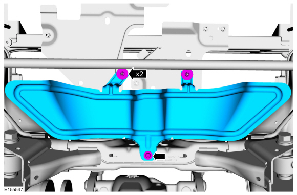
If equipped.
Remove the retainers and the underbody shield.
-
Remove the retainers and the underbody shields.
-
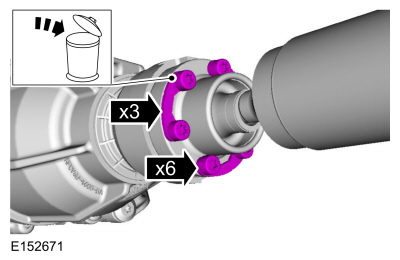
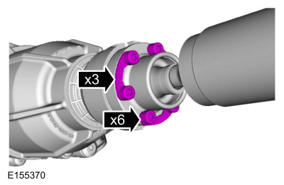
Remove and discard the driveshaft-to-RDU (rear drive unit) retainers.
-
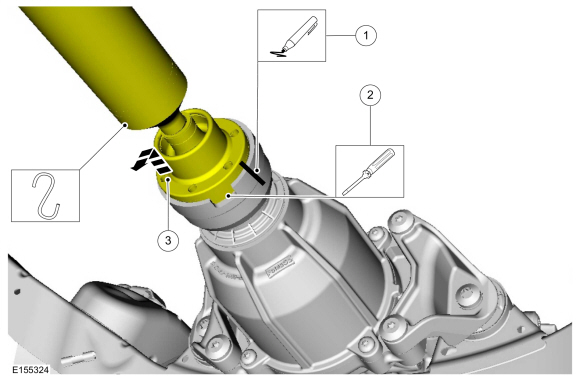
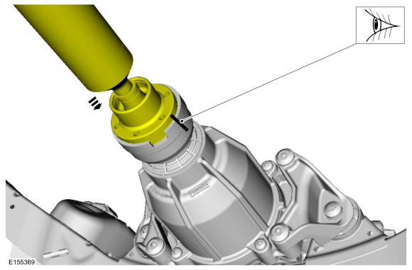
NOTE:
Do not remove driveshaft from the pinion flange by
pulling on the driveshaft tube. Damage to the CV-joint can result.
-
Index-mark the driveshaft and pinion flange.
-
Using screwdriver, separate the driveshaft from the pinion flange.
-
Position aside and support the driveshaft.
-
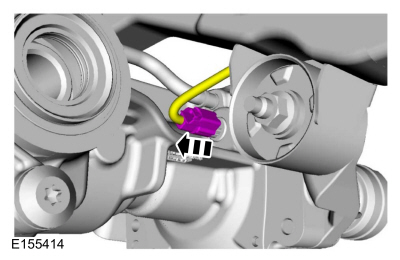
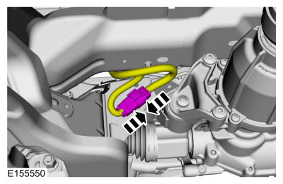
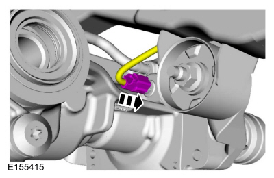
Disconnect the RDU electrical connector.
-
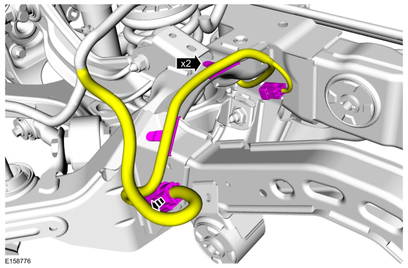
Discconect electrical connector.
-
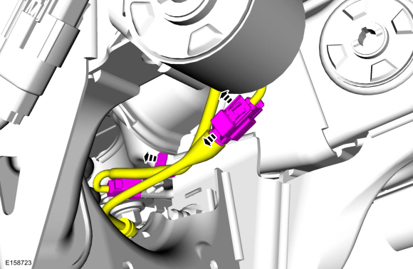
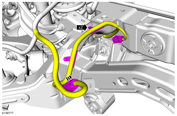
On both sides.
Detach the harness retainer and disconnect the electrical connectors.
-
Detach the harness retainers and disconnect the electrical connectors.
-
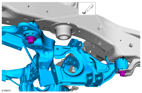
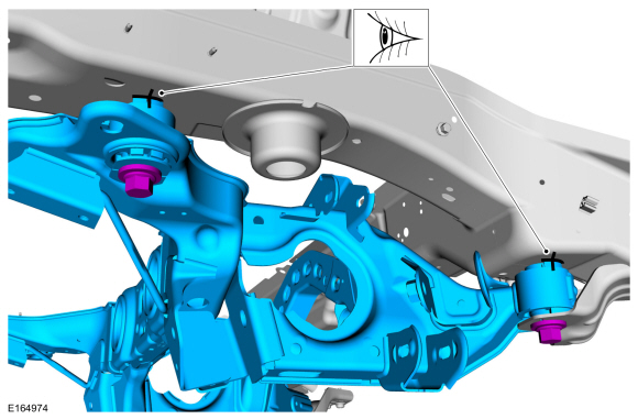
NOTE:
Index-mark the subframe for reference during installation.
On both sides.
Mark the position of the rear subframe.
-
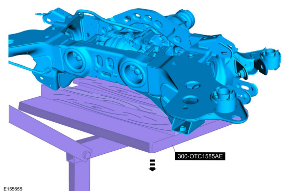
Position a powertrain lift and wooden blocks under the rear subframe.
Use Special Service Tool: 300-OTC1585AE
Powertrain Lift.
Use the General Equipment: Wooden Block
-
-
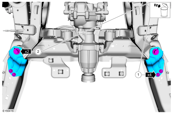
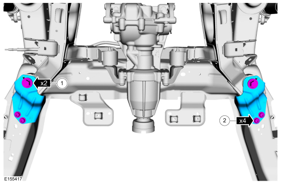
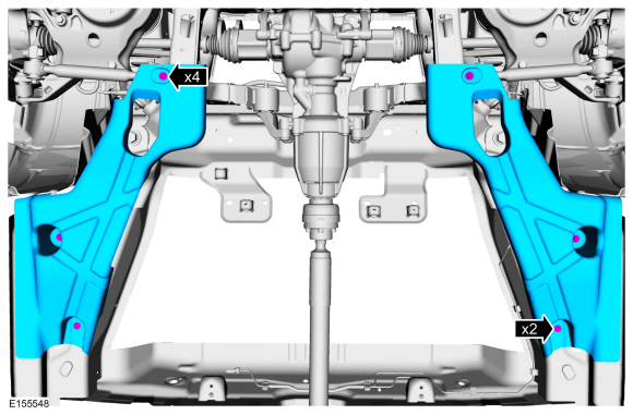
Remove and discard the rear subframe bracket bolts.
-
Remove and discard the rear subframe forward bolts.
-
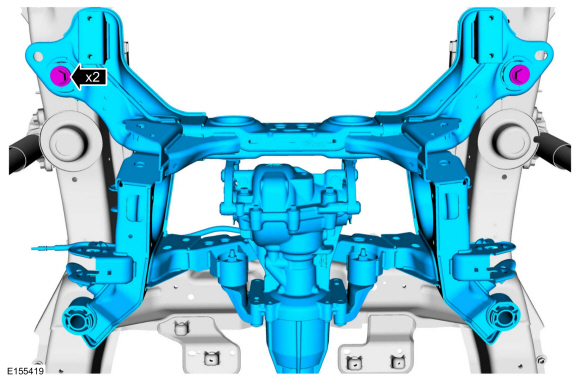
Remove and discard the rear subframe rearward bolts.
-
Lower the rear subframe.
Use Special Service Tool: 300-OTC1585AE
Powertrain Lift.
Use the General Equipment: Wooden Block
Installation
-
Partially raise the rear subframe and position it to the vehicle.
Use Special Service Tool: 300-OTC1585AE
Powertrain Lift.
Use the General Equipment: Wooden Block
-
On both sides.
Align the index marks made during removal.
-
-
Position the brackets and install the new rear subframe forward bolts.
Torque:
129 lb.ft (175 Nm)
-
Install the bracket bolts.
Torque:
41 lb.ft (55 Nm)
-
Install the rear subframe rearward bolts.
Torque:
129 lb.ft (175 Nm)
-
Attach the harness retainers and connect the electrical connectors.
-
On both sides.
Attach the harness retainer and connect the electrical connectors.
-
Connect the electrical connector.
-
Connect the RDU electrical connector.
-
NOTE:
Align the reference mark made during removal.
Position the driveshaft to the RDU flange.
-
Install the new driveshaft-to-RDU retainers.
Torque:
26 lb.ft (35 Nm)
-
Install the underbody shields and the retainers.
-
If equipped.
Install the underbody shield and retainers.
-
On both sides. Install the rear suspension height sensor.
Refer to: Rear Suspension Height Sensor (204-05 Vehicle Dynamic Suspension, Removal and Installation).
-
Install the rear stabilizer bar.
Refer to: Rear Stabilizer Bar (204-02 Rear Suspension, Removal and Installation).
-
Install the muffler and tailpipe.
Refer to: Muffler and Tailpipe (309-00B Exhaust System - 2.0L EcoBoost (184kW/250PS) – MI4, Removal and Installation).
Refer to: Muffler and Tailpipe (309-00B Exhaust System - 2.0L EcoBoost (184kW/250PS) – MI4, Removal and Installation).
-
On both sides. Install the spring.
Refer to: Spring (204-02 Rear Suspension, Removal and Installation).
-
On both sides. Install the toe link.
Refer to: Toe Link (204-02 Rear Suspension, Removal and Installation).
-
On both sides. Install the rear halfshaft.
Refer to: Rear Halfshaft (205-05 Rear Drive Halfshafts, Removal and Installation).
-
Calibrate the suspension system. Connect the scan tool
and carry out the Ride Height Calibration routine. Follow the scan tool
directions.