Ford Fusion: Handles, Locks, Latches and Entry Systems / Rear Door Latch. Removal and Installation
Removal
NOTE: LHside shown, RH side similar.
NOTE: Removal steps in this procedure may contain installation details.
-
Remove the exterior rear door handle.
Refer to: Exterior Rear Door Handle (501-14 Handles, Locks, Latches and Entry Systems, Removal and Installation).
-
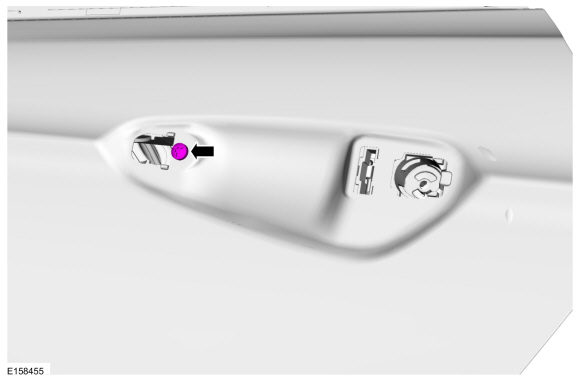
Remove the exterior rear door handle reinforcement screw.
Torque: 62 lb.in (7 Nm)
 |
-
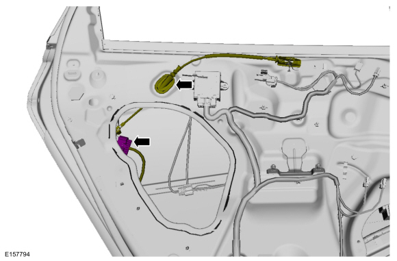
Disconnect the electrical connector and release the interior rear door handle cable routing clip.
 |
-
-
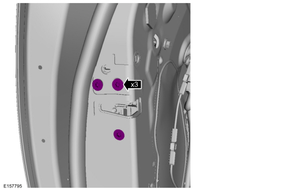
Remove the rear door latch bolts.
Torque: 71 lb.in (8 Nm)
-
Remove the rear door latch bolts.
 |
-
Remove the aft rear door glass run bolt.
Torque: 106 lb.in (12 Nm)
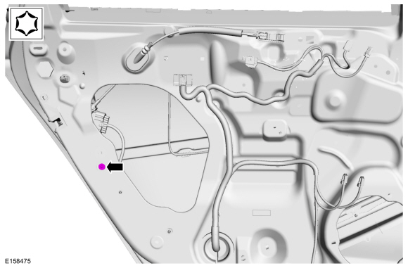 |
-
Remove the rear door latch.
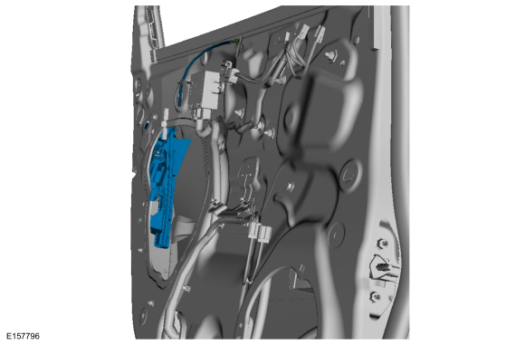 |
-
NOTE: This step is only necessary when installing a new component.
Remove the interior rear door handle cable from the rear door latch.
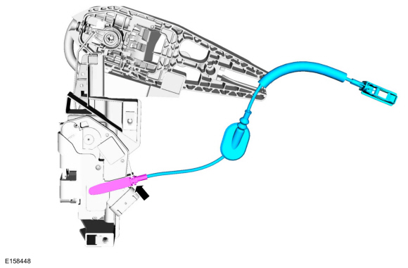 |
-
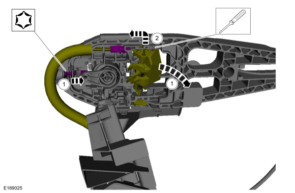
NOTE: This step is only necessary when installing a new component.
Remove the cable eyelet from the lever.
-
While turning the release screw the handle rotates the lever releasing the tension on the cable.
-
Remove the cable eyelet from the lever.
-
While turning the release screw the handle rotates the lever releasing the tension on the cable.
 |
-
NOTE: This step is only necessary when installing a new component.
Remove the rear door latch.
-
Remove the screws.
-
Detach and position aside the cable from the rear door latch.
-
Remove the screws.
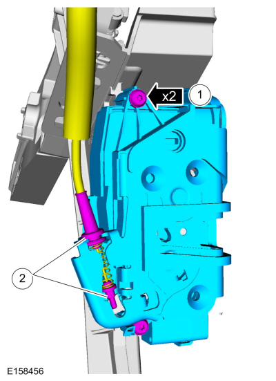 |
Installation
-
To install, reverse the removal procedure.
-
NOTE: This step is only necessary when installing a new component.
Install the rear door latch.
-
Install the screws.
-
Attach and position the cable from the rear door latch.
-
Install the screws.
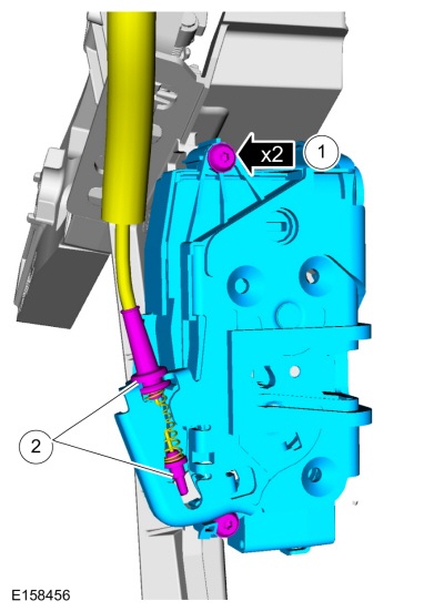 |
-
NOTE: This step is only necessary when installing a new component.
NOTE: This step must be done correctly or the exterior door handle will not engage the lever on installation.
Install the cable eyelet to the lever.
-
Install the cable eyelet to the lever.
-
While keeping tension on the cable and holding the
handle lever in the engaged position, turn the release screw until the
handle lever is positioned against the stop.
-
Install the cable eyelet to the lever.
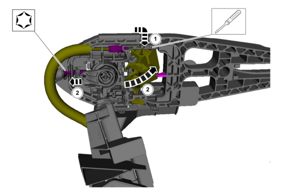 |
-
NOTE: This step is only necessary when installing a new component.
Install the interior rear door handle cable from the rear door latch.
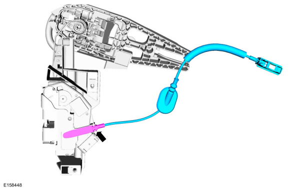 |
 Front Door Latch. Removal and Installation
Removal
NOTE:
LH side shown, RH side similar.
NOTE:
Removal steps in this procedure may contain installation details.
Remove the front door window regulator...
 Luggage Compartment Lid Latch. Removal and Installation
Special Tool(s) /
General Equipment
Flat-Bladed Screwdriver
Removal
NOTE:
Removal steps in this procedure may contain installation details...
Other information:
Ford Fusion 2013–2020 Service Manual: Fuel Charging and Controls - Component Location. Description and Operation
1.5L EcoBoost Item Description 1 High-pressure fuel pump 2 Fuel injector 3 Fuel rail 4 Throttle Body (TB) 5 High-pressure fuel pump mounting bracket FPDM Item Description 1 FPDM ..
Ford Fusion 2013–2020 Service Manual: Rear Stabilizer Bar. Removal and Installation
Removal NOTICE: Suspension fasteners are critical parts that affect the performance of vital components and systems. Failure of these fasteners may result in major service expense. Use the same or equivalent parts if replacement is necessary. Do not use a replacement part of lesser quality or substitute design. Tighten fasteners as specified. With the vehicle in NEUTRAL, position ..
Categories
- Manuals Home
- 2nd Generation Ford Fusion Owners Manual
- 2nd Generation Ford Fusion Service Manual
- Electronic Parking Brake (EPB) Service Mode Activation and Deactivation. General Procedures
- Automatic Transmission - 6-Speed Automatic Transmission – 6F35
- Load Carrying
- New on site
- Most important about car
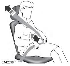
Using Seatbelts During Pregnancy
WARNING: Always ride and drive with your seatback upright and properly fasten your seatbelt. Fit the lap portion of the seatbelt snugly and low across the hips. Position the shoulder portion of the seatbelt across your chest. Pregnant women must follow this practice. See the following figure.