Ford Fusion: Driveshaft / Driveshaft Runout and Balancing. General Procedures
Special Tool(s) / General Equipment
 |
100-002
(TOOL-4201-C)
Holding Fixture with Dial Indicator Gauge |
Inspection
NOTE: Driveline vibration exhibits a higher frequency and lower amplitude then high-speed shake. Driveline vibration is directly related to the speed of the vehicle and is noticed at various speeds. Driveline vibration can be perceived as a tremor in the floorpan or heard as a rumble, hum or boom.
NOTE: Refer to Specifications in this section for runout specifications.
-
NOTE: Do not make any adjustments before carrying out a road test. Do not change the tire pressure or the vehicle load.
- Carry out a visual inspection of the vehicle. Operate the vehicle and verify the condition by reproducing it during the road test.
-
The concern should be directly related to vehicle
road speed. not affected by acceleration or deceleration or could be
reduced by coasting in NEUTRAL.
-
Refer to: Jacking and Lifting - Overview (100-02 Jacking and Lifting, Description and Operation).
-
NOTE: The driveshaft should be kept at an angle equal to or close to the curb-weighted position. Use a twin-post hoist or a frame hoist with jackstands.
- Inspect the driveshaft for damage, undercoating or incorrectly seated U-joints. Rotate the driveshaft slowly by hand and feel for binding or end play in the U-joint trunions. Remove the driveshaft. Inspect the slip yoke splines for any galling, dirt, rust or incorrect lubrication. Clean the driveshaft or install new U-joints as necessary. Install a new driveshaft if damaged. After any corrections or new components are installed, recheck for the vibration at the road test speed.
- If the vibration persists after inspection, measure the driveshaft runout.
 |
Check
-
NOTE:
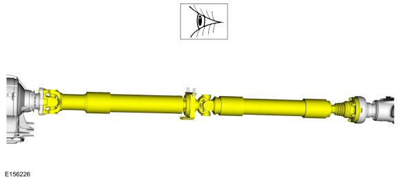
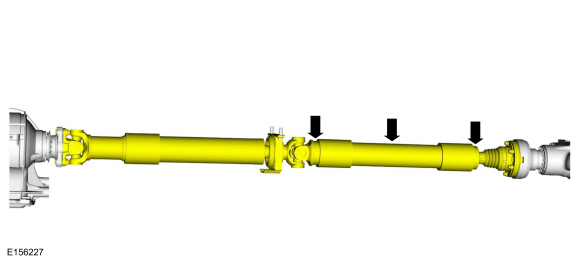
- Measure and check for the specified maximum value. Install the Dial Indicator Gauge with Holding Fixture. Rotate the driveshaft by turning the axle and measure the runout at the front, center and rear of the driveshaft. Multiple piece driveshaft measure each section at the front, center and rear.
-
If the runout exceeds 1 mm (0.040 in) at the front or center, install a new driveshaft.
Use Special Service Tool: 100-002 (TOOL-4201-C) Holding Fixture with Dial Indicator Gauge.
-
If the front and center is within 1 mm (0.040 in) ,
but the rear runout is not, index-mark the rear runout high point and
proceed to step 2.
-
If the runout is within 1 mm (0.040 in) at all
points, recheck for vibration at road test speed. If the vibration
persists, balance the driveshaft. Refer to Driveshaft Balancing in this
procedure.
 |
-
NOTE: Circular pinion flanges can be turned in 90 degree or one-fourth increments. Half-round pinion flanges are limited to 2 positions. CV joint pinion flanges that have 6 bolts, can be turned in 60 degree or one-sixth increments.
- Index-mark the driveshaft to the pinion flange. Disconnect the driveshaft and rotate it 180 degrees. Reconnect the driveshaft. Recheck the runout at the rear of the driveshaft.
-
If the runout is still over specification, mark the high point and proceed to Step 3.
-
If the runout is within specification, check for the
vibration at the road test speed. If the vibration is still present,
balance the driveshaft. Refer to Driveshaft Balancing in this procedure.
-
NOTE:
- Excessive driveshaft runout can originate in the driveshaft itself or from the pinion flange. To find the source, compare the 2 high points previously determined.
-
If the index marks are close together, within 25 mm
(1 in), the driveshaft is eccentric. Install a new driveshaft.
-
If the marks are on opposite sides of the
driveshaft, 180 degrees apart, the slip yoke or pinion flange is
responsible. Check the pinion flange runout. If the pinion flange runout
exceeds specifications, a bent pinion is indicated.
-
If the pinion flange and pinion runouts are within
specifications, road test and check for the vibration at the road test
speed. If the vibration persists, balance the driveshaft. Refer to
Driveshaft Balancing in this procedure.
 |
Driveshaft Balancing – Using the Mastertech® Series MTS 4000 Driveline Balance and NVH Analyzer (Vetronix)
-
Special Tool(s): Mastertech® Series MTS 4000
Driveline Balance and NVH Analyzer (Vetronix) 257-00018. Working under
the vehicle, install an accelerometer. The accelerometer can be attached
and mounted near either the transmission or differential end of the
driveshaft.
-
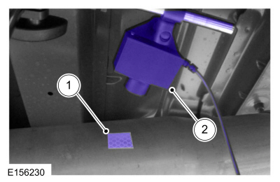
NOTE:
- Clean an area of the driveshaft and install the reflective tape, then install the photo-tachometer sensor. The sensor should be placed at approximately a 20-degree angle from perpendicular to the surface of the reflective tape. Make sure the sensor does not get moved during the balance procedure.
-
Reflective tape.
-
Photo-tachometer sensor.
 |
-
Special Tool(s): Mastertech® Series MTS 4000
Driveline Balance and NVH Analyzer (Vetronix) 257-00018. Run a
driveshaft balance test with the driveshaft unmodified.
Use Special Service Tool: 100-002 (TOOL-4201-C) Holding Fixture with Dial Indicator Gauge.
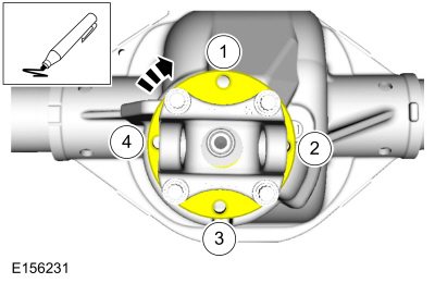
Vehicles with tapped pinion flanges
-
Label the tapped holes in the pinion flange
numerically, starting at the top hole as 1. Mark the remaining holes 2,
3, 4, (depending on flange type, 5 and 6 may also be needed). Label in
the direction of rotation.
 |
-
Special Tool(s): Mastertech® Series MTS 4000
Driveline Balance and NVH Analyzer (Vetronix) 257-00018. Run a second
test with the 12 mm (0.47 in) test weight set screw in the No. 1 hole,
previously marked on the pinion flange.
-
Remove the test weight, then install the weight
combination directed by the Mastertech® Series MTS 4000 Driveline
Balance and NVH Analyzer (Vetronix).
Vehicles without tapped pinion flanges
-
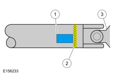
NOTE:
- Special Tool(s): Mastertech® Series MTS 4000 Driveline Balance and NVH Analyzer (Vetronix) 257-00018. Run a second test with a test weight. Using a metal band, secure the test weight to the end of the driveshaft. The weight should be placed at the end of the driveshaft tube, as close to the tube-to-yoke weld seam as possible. Mark the location of the test weight on the driveshaft, as shown in the figure below.
-
Test weight.
-
Tube-to-yoke weld seam.
-
Driveshaft pinion flange.
-
Select the test weight based on driveshaft size.
Larger driveshafts use 10 g (0.353 oz). Smaller driveshafts use 5 g
(0.176 oz).
 |
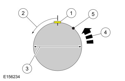
-
NOTE:
- Remove the test weight, then install the recommended weight at the position directed by the Mastertech® Series MTS 4000 Driveline Balance and NVH Analyzer (Vetronix). Using a metal band and epoxy, secure the test weight to the driveshaft, as shown in the figure below.
-
Test weight.
-
Measure in this direction.
-
Driveshaft diameter.
-
Directional rotation.
-
Balance weight relative to test weight centerline.
-
The results are displayed with respect to the location to where the test weight was placed.
 |
All vehicles
-
Special Tool(s): Mastertech® Series MTS 4000
Driveline Balance and NVH Analyzer (Vetronix) 257-00018. Run a third
test to verify the repair.
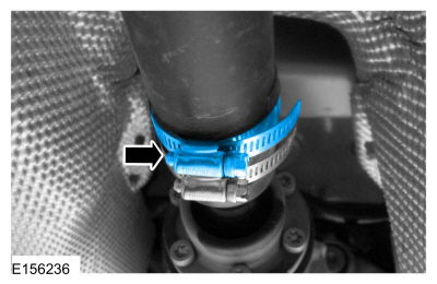
Driveshaft Balancing – Hose Clamp Method
-
Install 1 or 2 hose clamps on the driveshaft, near
the rear. Position of the hose clamp head(s) can be determined through
trial and error.
-
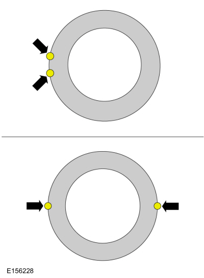
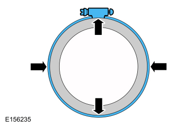
Mark the rear of the driveshaft into 4 approximately
equal sectors and number the marks 1 through 4. Install a hose clamp on
the driveshaft with its head at position No. 1, as shown in the figure
below. Check for vibration at road speed. Recheck with the clamp at each
of the other positions to find the position that shows minimum
vibration. If 2 adjacent positions show equal improvement, position the
clamp head between them.
 |
-
If the vibration persists, add a second clamp at the same position and recheck for vibration.
 |
-
If no improvement is noted, rotate the clamps in
opposite directions, equal distances from the best position determined
in Step 14. Separate the clamp heads about 13 mm (1/2 in) and recheck
for vibration at the road speed.
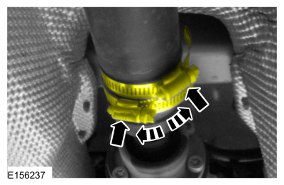 |
-
Repeat the process with increasing separation until
the best combination is found or the vibration is reduced to an
acceptable level.
 Driveshaft. Diagnosis and Testing
Preliminary Inspection
Visually inspect the CV joints for obvious signs of mechanical damage.
If an obvious cause for an observed or reported concern is
found, correct the cause (if possible) before proceeding to the next
step
If the cause is not visually evident, verify the symptom and REFER to Symptom Chart: NVH...
 Driveshaft Angle Measurement. General Procedures
Check
NOTE:
This procedure does not apply to CV joints, flex couplers or
double cardan joints that are used in some driveshafts. This check is
for single-cross and roller-style joints found in the driveshafts...
Other information:
Ford Fusion 2013–2020 Service Manual: Pinpoint Test - DTC: E. Diagnosis and Testing
B0010:11, B0010:12, B0010:13 and B0010:1A Refer to Wiring Diagrams Cell 46 for schematic and connector information. Normal Operation and Fault Conditions The RCM continuously monitors the passenger airbag stage 1 circuits for the following faults: Resistance out of range Unexpected voltage Short to ground Faulted passenger airbag If a fault is detected, t..
Ford Fusion 2013–2020 Owners Manual: Jump Starting the Vehicle
WARNING: Batteries normally produce explosive gases which can cause personal injury. Therefore, do not allow flames, sparks or lighted substances to come near the battery. When working near the battery, always shield your face and protect your eyes. Always provide correct ventilation. WARNING: Keep batteries out of reach of children. Batteries contain sulfuric acid. Avoid contact with ski..
Categories
- Manuals Home
- 2nd Generation Ford Fusion Owners Manual
- 2nd Generation Ford Fusion Service Manual
- Automatic Transmission - 6-Speed Automatic Transmission – 6F35
- Powertrain
- Automatic Transmission Fluid Check - 1.5L EcoBoost™/2.0L EcoBoost™/2.5L. Automatic Transmission Fluid Check - 2.7L EcoBoost™
- New on site
- Most important about car
Manual Climate Control

Note: Depending on your vehicle option package, the controls may look different from what you see here.