Ford Fusion: Instrumentation, Message Center and Warning Chimes / Instrument Panel Cluster (IPC) - System Operation and Component Description. Description and Operation
System Operation
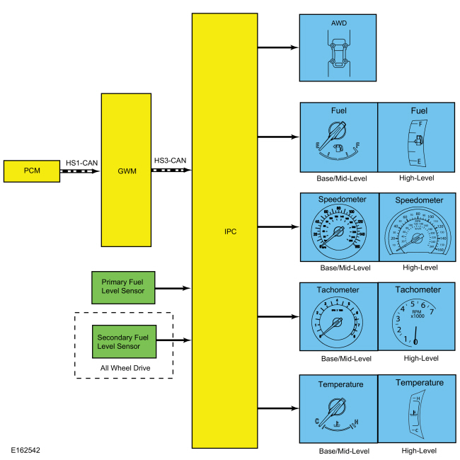
System Diagram - Gauges
.jpg)
| Item | Description |
|---|---|
| 1 | Base/mid-level |
| 2 | High-level |
| 3 | Base/mid-level |
| 4 | High-level |
| 5 | Base/mid-level |
| 6 | High-level |
| 7 | Base/mid-level |
| 8 | High-level |
| 9 | AWD |
| 10 | Temperature |
| 11 | Tachometer |
| 12 | HS-CAN1 |
| 13 | IPC |
| 14 | GWM |
| 15 | PCM |
| 16 | HS-CAN3 |
| 17 | Primary fuel level sensor |
| 18 | Tachometer |
| 19 | Temperature |
| 20 | Speedometer |
| 21 | Fuel |
| 22 | Fuel |
| 23 | Speedometer |
| 24 | Secondary fuel level sensor |
| 25 | AWD |
Network Message Chart - Gauges
Module Network Input Messages - IPC
| Broadcast Message | Originating Module | Message Purpose |
|---|---|---|
| AWD data | PCM | Input used for the virtual AWD gauge display. |
| Engine coolant temperature data | PCM | Input used for the temperature gauge indication. |
| Engine overheat indication request | PCM | Input used to send the temperature gauge to full hot. |
| Engine rpm data | PCM | Input used for tachometer indication. |
| Ignition status | BCM | Ignition RUN, START and accessory states required for the IPC operating modes and fault reporting. |
| Vehicle speed | PCM | Vehicle speed data used for the virtual AWD gauge display and speedometer indication. |
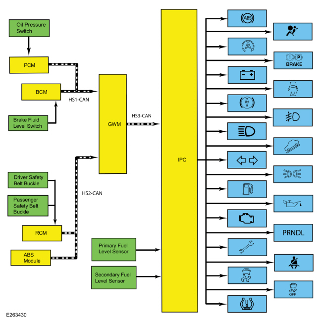
System Diagram - Indicators
.jpg)
| Item | Description |
|---|---|
| 1 | RCM |
| 2 | ABS module |
| 3 | IPC |
| 4 | Brake fluid level switch |
| 5 | Driver safety belt buckle |
| 6 | PCM |
| 7 | Passenger safety belt buckle |
| 8 | GWM |
| 9 | BCM |
| 10 | Secondary fuel level sSensor |
| 11 | Primary fuel level sensor |
| 12 | Oil pressure switch |
Network Message Chart - Indicators
Module Network Input Messages - IPC
| Broadcast Message | Originating Module | Message Purpose |
|---|---|---|
| ABS warning indicator request | ABS module | Input used to control the ABS warning indicator. |
| Airbag warning indicator request | RCM | Input used to control the airbag warning indicator. |
| AWD service required | PCM | Input used to control the powertrain malfunction (wrench) indicator |
| Body service required | BCM | Input used to control the powertrain malfunction (wrench) indicator |
| Brake warning indicator request | ABS module | Input from the ABS for the parking brake input used to control the brake warning indicator. |
| Brake (red) warning indicator request | ABS module | Input from the ABS used to control the brake warning indicator. |
| Charging system indication request | BCM | Input used to control the charging system warning indicator. |
| Door ajar status | BCM | Input used to control the door ajar warning indicator. |
| Driver safety belt buckle status | RCM | Input used to control the safety belt warning indicator. |
| Engine rpm data | PCM | Input used to control the low oil pressure warning indicator. |
| Engine service required | PCM | Input used to control the powertrain malfunction (wrench) indicator |
| Fog lamp indicator request | BCM | Input used to control the fog lamp indicator. |
| High beam status | BCM | Input used to control the high beam indicator. |
| Ignition status | BCM | Ignition RUN, START and accessory states required for the IPC operating modes and fault reporting. |
| MIL request | PCM | Input used to control the MIL. |
| Oil pressure warning indicator request | PCM | Input used to control the low oil pressure warning indicator. |
| Parking brake warning indicator request | ABS module | Input used to control the parking brake indicator. |
| Parklamp status | BCM | Input used to control the lights on indicator. |
| Red brake warning indicator request | BCM | Input for the brake fluid level status used to control the brake warning indicator. |
| Stability-traction control indicator request | ABS module | Input used to control the stability/traction control (sliding car icon) indicator. |
| Stability-traction control disabled indicator request | ABS module | Input used to control the stability/traction control disabled (sliding car OFF icon) indicator. |
| Stop/start indicator request | PCM | Input used to control the auto stop/start indicator. |
| Tire pressure warning indicator | BCM | Input used to control the TPMS indicator. |
| Transmission gear display actual | PCM | Input used to display or flash the PRNDL indication. |
| Transmission service required | PCM | Input used to control the powertrain malfunction (wrench) indicator |
| Transmission shift mode display | PCM | Input used to control the select shift segment of the PRNDL indication. |
| Transmission shift mode request | ABS module | Input used to control the grade assist indicator. |
| Turn indication status | BCM | Input used to control the RH turn, LH turn and hazard indicators. |
Networked Input Messages and Default States
NOTE: Whenever a network message is suspected as missing and confirmed by a missing message DTC (U-code), it is important to look for other symptoms that can also be present in the IPC and throughout the vehicle. Once a DTC sets in the IPC, it is helpful to review the complete message list to determine which other modules also rely on the same message and run the self-test for those modules. If the message is missing from other modules, the same or similar lost communication DTC can also be set in those modules. Confirmation of missing messages common to multiple modules can indicate the originating module is the source of the concern or the communication network may be faulted.
For a list of all the network messages,
Refer to: Communications Network - System Operation and Component Description (418-00 Module Communications Network, Description and Operation).
The IPC uses input messages from other modules to control the gauges, informational indicators, warning indicators and message center message displays over the communication networks. The IPC receives all networked data over the HS-CAN3.
The vehicle uses 4 communication networks to transmit the data used by the IPC.
- HS-CAN1
- HS-CAN2
- HS-CAN3
- MS-CAN
Refer to: Communications Network - Overview (418-00 Module Communications Network, Description and Operation).
or Refer to: Communications Network - System Operation and Component Description (418-00 Module Communications Network, Description and Operation).
All messaged inputs to the IPC from other networks are received from the GWM over the HS-CAN3. The GWM, as the name implies, acts as a gateway to convert messages from one of the other 3 networks to the HS-CAN3, which is recognized by the IPC.
Network messages can drop out or be missing for a variety of reasons, such as high network traffic on the bus. The IPC incorporates a defined strategy for handling missing network messages based on time. The required time for a network message to be missing differs between the various gauges, indicators and message center displays. The strategy is basically the same for all indication outputs (gauges, indicators or chimes), but differs in the length of time required for the network message to be missing. If a required network message is missing or invalid for less than the programmed length of time, the gauge, indicator or message center display that requires the network message remains at the last commanded state based upon the last network message received. If the messaged input is missing for longer than the programmed length of time, the IPC output (gauge, indicator etc.) reacts according to a pre-defined default action.
For example, if the stability-traction control indicator request network message is missing for less than 5 seconds, and the stability-traction control indicator (sliding car icon) was on, the indicator remains in the on state until the next network message is received. If the network message remains missing or invalid for more than 5 seconds, the IPC sets a U-code DTC and the IPC output becomes a default action for the indicator or gauge. The indicator may default on/off or the gauge may default to the rest position.
Each indicator or gauge utilizes a different default strategy depending on the nature of the indication. Refer to the diagnostic overview descriptions located before each pinpoint test for further descriptions of the default action specific to each indicator or gauge. If the missing messaged input to the IPC returns at any time, the normal function of the gauge, indicator or message center display resumes.
It is very important to understand:
- where the input originates.
- all the information necessary in order for a feature to operate.
- which module(s) receive(s) the input or command message.
- which module controls the output of the feature.
- whether the module that receives the input controls the output of the feature, or whether it outputs a message over the communication network to another module.
Startup-Shutdown
The IPC provides a startup/shutdown sequence also known as a welcome/goodbye strategy. The IPC initiates and follows a progressive strategy providing increasing IPC functionality from IPC wake up to ready to drive status. This sequence begins at RKE unlock or driver door open through the ignition RUN state. During this period, the IPC provides increasing functionality from backlighting or illuminating gauge rings, gauge pointers, illuminating the PRNDL, backlighting of the message center display, displaying a message center splash screen, gauge and LED prove out, gauge sweep and finally normal IPC operation.
MyKey®
The MyKey® feature allows the customer to program a restricted driving mode that is tied to one or more keys known as a MyKey® key. The following features are provided by the IPC when a MyKey® key is being used:
- At the beginning of vehicle start up, as part of the welcome strategy, the message center greets the MyKey® driver with MYKEY ACTIVE DRIVE SAFELY displayed in the message center. If the MyKey® speed limiter feature is turned on, the message center also displays the MyKey® administrator selected top speed setting message; SPEED LIMITED TO XXX KM/H (XX MPH). The MyKey® top speed selections are; 100, 110, 120 or 130 kmh (62, 68, 75, or 81 mph) or to the administrator desired setpoint.
- The IPC provides a periodic Belt-Minder® warning chime until the driver and passenger safety belts are buckled. When the Belt-Minder® is issued, the ACM is muted and the message center displays BUCKLE UP TO UNMUTE AUDIO.
- If the MyKey® speed limiter feature is turned on and the vehicle speed approaches the selected top speed (100, 110, 120 or 130 kmh [62, 68, 75, or 81 mph]), the message center displays NEAR VEHICLE TOP SPEED along with a chime.
- If the MyKey® speed limiter feature is turned on and the vehicle speed reaches the selected top speed (100, 110, 120 or 130 kmh [62, 68, 75, or 81 mph]), the message center displays TOP SPEED MYKEY SETTING along with a chime.
- If the speed warning is selected at one of the preset values (75, 90, 100 km/h [47, 56, 62 mph]) and the vehicle approaches the preset speed, the message center displays CHECK SPEED DRIVE SAFELY along with a chime.
- At 80 km (50 miles) DTE, the IPC illuminates the low fuel RTT indicator and the message center displays FUEL LEVEL LOW along with a chime.
- Traction control, Emergency 911 Assist® feature and the Do Not Disturb feature can be set to always on or user selectable in the MyKey® menu.
- If the traction control always on feature is turned on and the MyKey® driver attempts to disable the traction control, the message center displays ADVANCETRAC ON MYKEY SETTING.
- MyKey® miles driven by the MyKey® user can be found in the information display.
- The number of MyKey® programmed and administrator keys can be found in the MyKey® menu.
- The parking aid, Blind Spot Monitoring System/Cross Traffic Alert (BLIS® /CTA), lane departure alert (lane departure alert menu is not disabled for every MyKey® ignition cycle, however, the lane departure would be set to alert only and the MyKey® user will have the capability to change it to other options “alert only, aid only, both or off”) and collision avoidance warning menus are disabled in the message center to force these features always on.
When an administrator key is in use, the IPC provides:
- a menu in the message center guiding the user to create a MyKey®. When the maximum MyKey® limit is reached, the MyKey® creation menu is no longer available.
-
a menu in the message center with options for setting 6 MyKey® features:
- MyKey® speed limiter.
- MyKey® pre-selected speed warning.
- MyKey® radio volume limiter.
- traction control always on or user selectable.
- emergency 911 assist feature always on or user selectable.
- do not disturb feature always on or user selectable.
- a menu in the message center with the option to clear all MyKey® programmed keys at once.
- MyKey® mileage driven by the MyKey® user can be found in system check function of the message center.
- the number of MyKey® programmed keys and administrator keys can be found in the system check function of the message center.
For information on the MyKey® features, refer to the Owner's Literature.
Configuration
The IPC
contains items that are configurable. Most of the configurable items
(configurable parameters) are customer preference items, which can be
set with a scan tool. The remaining configurable items can only be set
through the vehicle configuration parameters.
Refer to: Module Configuration - System Operation and Component Description (418-01 Module Configuration, Description and Operation).
Prove-Out
The IPC carries out a display prove-out to verify the gauges function and all module controlled warning indicator lamps and monitored systems are functioning correctly within the IPC. Upon initiation of the prove-out, the gauges sweep from one stop to the other then return to the normal indication state based on the input received. The IPC also provides a timed prove-out of some indicators while other indicators illuminate upon engine start up or have no prove-out. When the ignition is cycled on, the indicators illuminate to prove-out according to the following table:
| Indicator | Indicator Type | Prove-Out Duration |
|---|---|---|
| Airbag | Warning | 6 seconds |
| ABS | Warning | 3 seconds |
| Auto stop/start | Informational | None |
| Brake | Warning | 3 seconds |
| Electric park brake | Informational | 3 seconds |
| Fog lamp | Informational | None |
| Grade assist | Informational | 3 seconds |
| High beam | Informational | None |
| MIL | Informational | Engine start up |
| Lights on | Informational | None |
| Safety belt | Informational | 65 seconds if the safety belt is unbuckled, turns off when the safety belt is buckled |
| Stability-traction control (sliding car icon) | Warning | 3 seconds |
| Stability-traction control disabled (sliding car OFF icon) | Informational | 3 seconds |
| TPMS | Warning | 3 seconds |
| Turn indicators | Informational | None |
Dealer Test Mode
NOTE: The table lists the displays as they appear when navigating using the down arrow button.
To enter the IPC engineering test mode or dealer test mode, begin with the ignition OFF. Press and hold the LH steering wheel switch OK button. Place the ignition ON and continue to hold the button for 5-8 seconds until the display indicates Test or Gauge Sweep. Press the up or down arrow buttons to navigate through each of the display windows. To exit the IPC dealer test mode, press and hold the OK button for 5-8 seconds or place the ignition in OFF. Each down arrow button press advances the viewing window to the next set of items.
| IPC Display | Description |
|---|---|
|
Initial entry display into the dealer test mode. |
|
Carries out the gauge sweep of the analog gauges. When the sweep (zero to maximum then return to zero) is complete, the actual data is displayed. |
|
Illuminates all cluster microprocessor controlled LED telltales or indicators. Also displays a color palette of boxes below the title. |
|
Displays the IPC part number information. |
|
|
|
Displays all of the Diagnostic Trouble Codes (DTCs) set (history and current Diagnostic Trouble Codes [DTCs]). An X in the HIST or CURR column means the DTC is active. Three Diagnostic Trouble Codes (DTCs) display on each screen. If more Diagnostic Trouble Codes (DTCs) are present, there will be additional screens listing them. If there are no Diagnostic Trouble Codes (DTCs) in history or current, the display will only be the title row. |
|
|
|
Displays the instant fuel level and filtered fuel level in percent. This is used for a single sender fuel level input. |
|
Displays the instant fuel level and filtered fuel level in percent. This is used for the fuel pump assembly input on a dual sender fuel tank configuration. |
|
Displays the instant fuel level and filtered fuel level in percent. This is used for the fuel level sensor input on a dual sender fuel tank configuration. |
|
Displays the values used for calculating the DTE function. |
|
Displays the running average fuel economy. The values are derived from the DTE function. |
|
Displays the key ON initialization, key OFF reference, and zero speed reference fuel level values in fuel level for a single sender fuel level input. |
|
Displays the key ON initialization, key OFF reference, and zero speed reference fuel level values in fuel level for the fuel pump assembly input on a dual sender fuel tank configuration. |
|
Displays the key ON initialization, key OFF reference, and zero speed reference fuel level values in fuel level for the fuel level sensor input on a dual sender fuel tank configuration. |
|
Displays the digital representation of the coolant temperature gauge indication in degrees Celsius. |
|
Displays the values from the odometer count signal and the trip A statistics. |
|
Displays the values from the odometer count signal and the trip B statistics. |
|
Displays the values of the fuel flow display signal from the PCM and the approximate fuel used for the trip stats A. |
|
Displays the values of the fuel flow display signal from the PCM and the approximate fuel used for the trip stats B. |
|
|
|
|
|
|
|
Park detect switch (0 = open/not park, 1 = closed/park). |
|
Repeats the test display cycle. |
AWD Gauge
The AWD gauge is a virtual gauge that displays the level of power applied to each wheel. The AWD system is almost always active, it is transferring torque whenever the vehicle is accelerating, boosting output when wheels are slipping, and shutting off on the highway to save fuel. The IPC uses the following inputs to determine the AWD gauge display:
- Wheel torque data
- AWD lock torque
- Vehicle speed
As power is applied to the wheels, the area directly in front of each displayed wheel begins to fill in. The lowest power displayed is the closest to the wheel. As the amount of power sent to the wheels increases, the area fills in either forward (front wheels) or rearward (rear wheels) of the wheels.
The IPC receives the AWD data and the vehicle speed messages from the GWM over the HS-CAN3. The GWM receives the AWD data and the vehicle speed messages from the PCM over the HS-CAN1.
Fuel Gauge
The fuel gauge is an analog gauge on the base and optional mid-level IPC. The fuel gauge is a virtual gauge on the optional high-level IPC.
The IPC sends a reference voltage to the fuel level sender(s). As the fuel level changes, a float actuates the variable resistor fuel level sender, raising or lowering the fuel level signal voltage. The IPC monitors the changes in voltage from both senders and commands the fuel gauge with a corresponding movement of the pointer.
After a fuel fill up, the time for the fuel gauge to move from empty (E) to full (F) ranges from 2 seconds to 55 minutes depending on which operating mode the fuel gauge is in.
The IPC uses 4 different operating modes to calculate the fuel level:
- Anti-slosh (default mode)
- Key OFF fueling
- Key ON fueling
- Recovery
The default fuel gauge mode is called the anti-slosh mode. To prevent fuel gauge changes from fuel slosh (gauge instability due to changes in fuel sensor readings caused by fuel moving around in the tank), the fuel gauge takes approximately 40 minutes to go from empty (E) to full (F).
The key OFF fueling mode (2 seconds to read empty [E] to full [F]) requires 3 conditions to be met:
- The ignition must be in the OFF mode when refueling the vehicle.
- At least 6% of the vehicle's fuel capacity must be added to the fuel tank.
- The IPC must receive a valid ignition ON fuel sensor reading within one second of the ignition being put into the RUN mode. The key ON sample readings are considered valid if the fuel sensor reading is between 10 ohms ± 2 ohms and 180 ohms ± 4 ohms.
If these conditions are not met, the fuel gauge stays in the anti-slosh mode, which results in a slow to read full (F) event.
The key ON fueling mode (approximately 60 seconds to read empty [E] to full [F]) requires the following conditions be met:
- The transmission is in PARK (P) or NEUTRAL (N).
- The ignition is in the RUN mode.
- At least 6% of the vehicle's fuel capacity must be added to the fuel tank
In key ON fueling mode, a 30-second timer activates after the transmission is put into the PARK (P) or NEUTRAL (N) position. When the 30-second time has elapsed and at least 9% of the vehicle's fuel capacity has been added, the fuel gauge response time is 60 seconds to read from empty (E) to full (F). When the transmission is shifted out of PARK (P) or NEUTRAL (N), the fuel gauge strategy reverts to the anti-slosh mode. The key ON fueling mode prevents slow to read full events from happening if the customer refuels the vehicle with the ignition in the RUN mode.
Recovery mode is incorporated into the IPC strategy to recover from a missing fuel level input after a refueling event. Missing fuel level inputs result from intermittent opens in the fuel sensor or its circuits. Recovery mode (empty [E] to full [F] approximately 17 minutes) is initiated when the following 2 conditions are met:
- The IPC is in the anti-slosh (default) mode.
- The actual fuel level in the tank is 5% different from what is being displayed by the fuel gauge.
Speedometer
The IPC receives the vehicle speed data from the GWM over the HS-CAN3. The GWM receives the vehicle speed message from the PCM over the HS-CAN1. The PCM receives the wheel speed data from the ABS. The PCM uses tire size stored in the vehicle configuration file along with wheel speed inputs to generate a vehicle speed signal.
The IPC provides a tolerance that allows the speed indication to display between 3% below and 7% above the actual vehicle speed. This means that with an actual vehicle speed of 97 km/h (60 mph), the speedometer can indicate between 94-103 km/h (58-64 mph). Incorrect tire size or tire size configuration could potentially affect the speedometer accuracy.
Tachometer
The tachometer is an analog gauge on the base and optional mid-level IPC. The temperature gauge is a virtual gauge on the optional high-level IPC.
The IPC receives the engine rpm data message from the GWM over the HS-CAN3. The GWM receives the engine rpm data message from the PCM over the HS-CAN1.
Temperature Gauge
The temperature gauge is an analog gauge on the base and optional mid-level IPC. The temperature gauge is a virtual gauge on the optional high-level IPC. The IPC uses 2 messages to control the temperature gauge. The first is the engine coolant temperature data, which provides the current engine temperature input to the PCM. The second message is the engine overheat indication request, which is sent by the PCM to the IPC when an overheating condition exists. When the IPC receives the engine overheat indication request message, the IPC sends the temperature gauge to full hot and turns on the over-temperature warning indicator.
The IPC receives all the temperature gauge inputs from the from the GWM over the HS-CAN3. The GWM receives the engine coolant temperature data, heater core temperature and the engine overheat indication request messages from the PCM over the HS-CAN1.
ABS Warning Indicator
The IPC receives the ABS warning indicator request message from the GWM over the HS-CAN3. The GWM receives the ABS warning indicator request message from the ABS module over the HS-CAN2. If a fault condition exists in the ABS, the ABS module sends the ABS warning indicator request message to either flash or illuminate the ABS warning indicator.
Refer to ABS/Brake/Stability-Traction Control System Indication description for information on the conditions when the ABS warning indicator is turned on.
ABS/Brake/Stability-Traction Control System Indication
The brake/stability-traction control system indication is controlled almost entirely by the ABS module. The ABS module can illuminate multiple indicators for various fault conditions. The following table provides a summary of the basic fault conditions and the indicators that are illuminated for each condition.
NOTE: Refer to the Normal Operation and Fault Condition description before each brake/stability-traction control system indicator Pinpoint Test (PPT) for the IPC default action for network/missing message conditions.
NOTE: All states listed below assume the parking brake is unapplied unless specifically stated in the event/fault condition column or specified in the status column.
| Event/Fault Condition | ABS Warning Indicator Status | Red Brake Warning Indicator Status | Amber Electric Park Brake Indicator Status | Stability-Traction Control Indicator Status | Stability-Traction Control Disabled Indicator Status |
|---|---|---|---|---|---|
| Stable driving (no control events occurring) | Off | Off or on if conditions such as low brake fluid level exist. | Off | Off | Off |
| Parking brake applied | Off |
|
Off | Off | Off |
| ACC and ABS control event active | Off | Off | Off | Flashing | Off |
| Stability-traction control disabled by driver | Off | Off | Off | Off | On |
| Low brake fluid level or brake fluid level input concern | Off | On | Off | Off | Off |
| Stability-traction control event without brake pedal applied | Off | Off | Off | Flashing | Off |
| Stability-traction control event | Off | Off | Off | Flashing | Off |
| Single wheel speed sensor faults | On | Off or on if conditions such as low brake fluid level exist. | Off | On | On |
| 2 or 3 wheel speed sensor faults | On | Flashing | On | On | On |
| HCU valve fault | On | On | Off | On | On |
| ABS module fault | On | Flashing | On | On | On |
| ABS battery voltage faults | On | Flashing or on | On | On | On |
| ABS pump motor fault | On | On | Off | On | On |
| HCUpressure sensor fault (master cylinder pressure input) | Off | Off or on if conditions such as low brake fluid level exist. | Off | On | On |
| ABS low brake booster vacuum or vacuum sensor fault | Off | On | Off | Off | Off |
| Steering wheel angle sensor center not found fault | Off | Off | Off | On | On |
| Parking brake switch fault | On | Flashing | On | Off | Off |
| Configuration mismatch | Off | Off or on if conditions such as low brake fluid level exist. | Off | Off | Off |
| Vehicle Identification Number (VIN) mismatch | On | Off or on if conditions such as low brake fluid level exist. | Off | On | On |
Airbag Warning Indicator
The IPC receives the airbag warning indicator request from the GWM over the HS-CAN3. The GWM receives the airbag indicator request from the RCM over the HS-CAN2. If a SRS concern is detected, the RCM sets a DTC and the IPC illuminates the airbag warning indicator.
Auto Stop/Start Indicator
The auto stop/start indicator informs the driver of the following states:
- Solid green-the auto stop/start feature has temporarily turned off the motor.
- Solid amber-a stop/start system concern exists.
- Flash in either green or amber-system state as determined by the PCM.
- Grayed out (mid-level IPC) indicates the auto stop/start feature is not available.
The IPC receives the stop/start indicator request from the GWM over the HS-CAN3. The GWM receives the auto stop/start indicator request from the PCM over the HS-CAN1.
Brake Warning Indicator
The brake warning indicator informs the driver the brake fluid level is low, there is a failure in the base brake system or the electric park brake is applied. The IPC uses 3 messaged inputs to control the brake warning indicator.
The IPC receives the brake (red) warning indicator request, the brake warning indicator request and the red brake warning indicator request from the GWM over the HS-CAN3.
The GWM receives the brake (red) warning indicator request and the brake warning indicator request from the ABS module over the HS-CAN2.
The GWM receives the red brake warning indicator request from the BCM over the HS-CAN1.
Refer to ABS/Brake/Stability-Traction Control System Indication description for information on the conditions when the brake warning indicator is turned on.
Electric Park Brake Indicator
The electric park brake indicator indicates a fault in the electric park brake system. The IPC receives the Parking brake warning indicator request from the GWM over the HS-CAN3. The GWM receives the Parking brake warning indicator request from the ABS module over the HS-CAN2.
Fog Lamp Indicator
The fog lamp indicator informs the driver that the fog lamps are turned on. The IPC receives the fog lamp indicator request from the GWM over the HS-CAN3. The GWM receives the fog lamp indicator request from the BCM module over the HS-CAN1.
Grade Assist
The grade assist indicator informs the driver the grade assist function is turned on and is in ready mode. The IPC receives the transmission shift mode request message from the GWM over the HS-CAN3. The GWM receives the transmission shift mode request message from the PCM over the HS-CAN1.
High Beam Indicator
The high beam indicator informs the driver that the high beams are turned. The IPC receives the high beam indicator request from the GWM over the HS-CAN3. The GWM receives the high beam indicator request from the BCM module over the HS-CAN1.
LH-RH Turn Signal/Hazard Indicator
When the multifunction switch is in the LH or RH turn position or if the hazard switch is on, the BCM sends the turn indication status message to the GWM over the HS-CAN1. The GWM sends the turn indication status message to the IPC over the HS-CAN3. Upon receipt of the applicable turn signal on/off data, the IPC flashes the turn signal indicator on and off.
Lights On Indicator
When the parking lamps are turned on, the BCM sends the parklamp status message to the GWM over the HS-CAN1. The IPC receives the parklamp status message from the GWM over the HS-CAN3 to illuminate the lights on indicator.
Low Fuel Indicator
The IPC uses the same hardwired inputs used to provide the fuel gauge indication. The IPC turns on the low fuel indicator when the fuel level is less than approximately 50 km (30 miles) DTE (without MyKey® key) or 80 km (50 miles) DTE (with MyKey® key).
Low Oil Pressure Indicator
The IPC uses the oil pressure warning indicator request and engine rpm data to control the low oil pressure indicator. The engine oil pressure switch is hardwired to the PCM. The PCM provides the oil pressure warning indicator request and the engine rpm data to the GWM over the HS-CAN1. The GWM provides the oil pressure warning indicator request and engine rpm data to the IPC over the HS-CAN3.
MIL
The IPC receives the MIL request from the GWM over the HS-CAN3. The GWM receives the MIL request from the PCM over the HS-CAN1.
Powertrain Malfunction (Wrench) Indicator
The IPC provides a powertrain malfunction (wrench) message center indicator to indicate transmission, Electronic Throttle Control (ETC), AWD, and BCM concerns.
The IPC receives all the required messages from the GWM over the HS-CAN3.
The GWM receives the transmission service required, engine service required and the AWD service required messages from the PCM over the HS-CAN1.
The GWM receives the body service required message from the BCM over the HS-CAN1.
PRNDL Indicator
The IPC uses the following messages to control the PRNDL:
- Transmission gear display actual
- Transmission shift mode display
- Vehicle speed
- Life cycle mode
The IPC receives the transmission gear display, transmission shift mode display and vehicle speed messages from the GWM over the HS-CAN3. The GWM receives the transmission gear display, transmission shift mode display and vehicle speed messages from the PCM over the HS-CAN1.
The IPC receives the life cycle mode message from the GWM over the HS-CAN3. The GWM receives the life cycle mode message from the BCM over the HS-CAN1. When the vehicle is in transport mode, the PRNDL is not displayed upon entry or exit from the vehicle to prevent battery drain during longer periods of time when the vehicle is not in use, such as those experienced during vehicle transport.
Safety Belt Warning Indicator
The RCM monitors the driver safety belt position through the driver safety belt buckle switch. The RCM provides the driver safety belt buckle status message to the GWM over the HS-CAN2. The GWM provides the driver safety belt status message to the IPC over the HS-CAN3 to either turn on or turn off the safety belt warning indicator.
Stability-Traction Control Disabled Indicator (Sliding Car OFF Icon)
The traction control is configured on/off through the message center. When the driver enables or disables the traction control system, the ABS module sends the stability-traction control disabled indicator request message to the GWM over the HS-CAN2. The GWM sends the stability-traction control disabled indicator request message to the IPC over the HS-CAN3 to illuminate or turn off the stability-traction control disabled indicator (sliding car OFF icon) based upon the system state.
Refer to ABS/Brake/Stability-Traction Control System Indication description for information on the conditions when the stability-traction control disabled indicator (sliding car OFF icon) is turned on.
When a MyKey® administrator has set the AdvanceTrac® feature to always on and a MyKey® programmed key is in use, the traction control system cannot be disabled. The menu selection in the message center used to disable the traction control system does not display when a MyKey® is in use, but remains active for the MyKey® administrator to select the AdvanceTrac® always on feature off. The stability-traction control indicator still functions normally to indicate a stability-traction control system fault and a stability-traction control active event.
Refer to ABS/Brake/Stability-Traction Control System Indication description for information on the conditions when the stability-traction control indicator (sliding car icon) is turned on.
Stability-Traction Control Indicator (Sliding Car Icon)
The IPC receives the stability-traction control indicator request message from the GWM over the HS-CAN3. The GWM receives the stability-traction control indicator request message from the ABS over the HS-CAN2.
Refer to ABS/Brake/Stability-Traction Control System Indication description for information on the conditions when the stability-traction control indicator (sliding car icon) is turned on.
TPMS Warning Indicator
The IPC receives the tire pressure warning indicator request from the GWM over the HS-CAN3. The GWM receives the tire pressure warning indicator request from the BCM over the HS-CAN1.
If the BCM determines the tire pressure has exceeded the low tire pressure limits, the tire pressure warning indicator request message is sent to the IPC to illuminate the TPMS warning indicator.
If a TPMS monitor or sensor fault condition exists, the BCM sends the tire pressure warning indicator request message to the IPC to flash the TPMS warning indicator. The IPC flashes the TPMS warning indicator for 75 seconds then turns the indicator on solid.
Component Description
Brake Fluid Level Switch
The brake fluid level switch is a reed type switch mounted in the master cylinder reservoir. The brake fluid level switch is hardwired to the BCM through a signal circuit and grounded through a separate body ground circuit. The BCM provides a reference voltage to the brake fluid level switch. When the brake fluid level is low, the float drops, allowing the reed switch to close, pulling the reference voltage low. When the brake fluid level is high, the float lifts, opening the switch contacts, sending the reference voltage high on the signal circuit to the BCM.
Fuel Level Sender
The fuel level sender is mounted to the fuel pump assembly or the fuel level sensor. The fuel level sender is a dual sweep potentiometer style resistor connected to a float mechanism. The dual sweep design provides a second resistance measurement that reduces the intermittent loss of data due to corrosion between the resistor wires and the sweep arm. As the fuel level changes, the float rises or falls with the fuel level moving the sweep arm across the resistor wires. This movement either increases or decreases the resistance through the unit. The fuel level sensor resistance ranges from 180 ohms ± 4 ohms at empty (E) to 10 ohms ± 2 ohms at full (F). When the fuel level is low, the fuel level sensor resistance is high. When the fuel level is high, the fuel level sensor resistance is low.
Both the fuel pump assembly and fuel level sensor are hardwired to the IPC through separate signal and return circuits. The fuel level return circuits are grounded internally in the IPC. The IPC provides a reference voltage on the fuel level signal circuit. As the fuel level changes, the change in resistance raises or lowers the fuel level signal voltage depending on the resistance of the fuel level sender.
IPC
The IPC provides the driver with a system status and alerts the driver when certain conditions exist in the vehicle. The IPC receives the ignition status from the BCM through the GWM over the HS-CAN3. The IPC requires Programmable Module Installation (PMI) when the IPC is replaced.
Oil Pressure Sensor (2.0L and 2.7L Engines)
The oil pressure sensor is hardwired to the PCM through VREF, signal and return circuits. The PCM provides the sensor voltage supply on the VREF circuit and monitors the change in voltage changes though the signal and return circuits as the oil pressure changes.
Oil Pressure Switch (1.5L and 2.5L)
The oil pressure switch is a normally open switch that is hardwired to the PCM through a single signal circuit. The ground is provided by the switch housing when it is mounted on the engine. The PCM provides a reference voltage to the oil pressure switch. When oil pressure is low, the oil pressure switch remains open, sending the reference voltage high. When the oil pressure is sufficient, the oil pressure switch closes, pulling the reference voltage low to the PCM.
Safety Belt Buckle Sensor
The safety belt buckles contain integrated sensors that are Hall-effect switches. The safety belt buckle sensors are serviced as one component with the safety belt buckle.

 Message Center - Overview. Description and Operation
Overview
The message center is an integral part of the IPC that receives and acts upon much of the same information that is input and used to operate the IPC
(gauges, informational indicators, and warning indicators)...
Other information:
Ford Fusion 2013–2020 Owners Manual: Breaking-In. Driving Through Water. Floor Mats
Breaking-In You need to break in new tires for approximately 300 mi (480 km). During this time, your vehicle may exhibit some unusual driving characteristics. Avoid driving too fast during the first 1,000 mi (1,600 km). Vary your speed frequently and change up through the gears early...
Ford Fusion 2013–2020 Service Manual: Seatbelt Cleaning. General Procedures
Cleaning WARNING: Do not bleach or re-dye the seatbelt webbing, as the webbing may weaken. Failure to follow this instruction may increase the risk of serious personal injury or death in a crash. Refer to the owner's literature for information on seatbelt care and the recommended cleaning solution to use...
Categories
- Manuals Home
- 2nd Generation Ford Fusion Owners Manual
- 2nd Generation Ford Fusion Service Manual
- Pre-Collision Assist (IF EQUIPPED)
- Engine
- Body Control Module (BCM). Removal and Installation
- New on site
- Most important about car
Understanding Your Tire Pressure Monitoring System
The tire pressure monitoring system measures pressure in your road tires and sends the tire pressure readings to your vehicle. You can view the tire pressure readings through the information display. The low tire pressure warning light will turn on if the tire pressure is significantly low. Once the light is illuminated, your tires are under-inflated and need to be inflated to the manufacturer’s recommended tire pressure. Even if the light turns on and a short time later turns off, your tire pressure still needs to be checked.