Ford Fusion: Instrument Panel and Interior Switches Illumination / Instrument Panel and Interior Switches Illumination - System Operation and Component Description. Description and Operation
System Operation
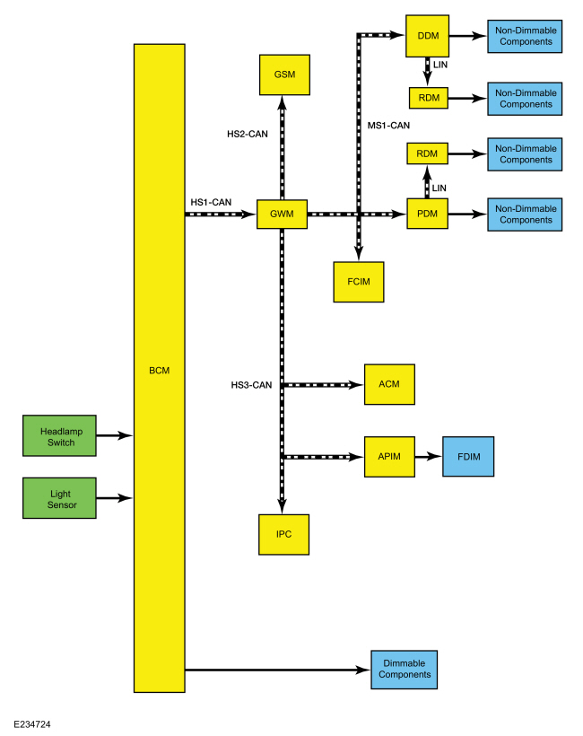
System Diagram
.jpg)
| Item | Description |
|---|---|
| 1 | FDIM |
| 2 | BCM |
| 3 | DDM |
| 4 | RDM |
| 5 | PDM |
| 6 | RDM |
| 7 | Headlamp Switch |
| 8 | Dimmable Components |
| 9 | GWM |
| 10 | Non-Dimmable Components |
| 11 | Non-Dimmable Components |
| 12 | Non-Dimmable Components |
| 13 | Non-Dimmable Components |
| 14 | Light Sensor |
| 15 | FCIM |
| 16 | APIM |
| 17 | ACM |
| 18 | IPC |
| 19 | GSM |
Network Message Chart
GSM, FCIM, IPC, ACM, RACM, APIM Network Input Messages
| Broadcast Message | Originating Module | Message Purpose |
| Illumination dimming level | BCM | Used to command the dimmable illumination level for networked modules. |
DDM, PDM Network Input Messages
| Broadcast Message | Originating Module | Message Purpose |
| Ignition status | BCM | Used to turn the non-dimmable illumination on or off for components wired to the DDM and the PDM. |
Dimmable Illumination
The BCM sends 2 voltage signals to the headlamp switch, one for the brightness increase and the other for brightness decrease. The illumination dimming level is controlled by the BCM. Based on the input from the instrument panel dimmer switch (integral to the headlamp switch), the BCM calculates the dimming level.
When the autolamp feature activates during the daytime, the message center illumination remains at full intensity and does not dim from the instrument panel dimmer switch. If the vehicle travels under a bridge or through a tunnel and a low level of ambient light is detected, the illumination brightness of the message center changes to the last level set by BCM. The message center illumination changes back to full intensity when the intense ambient light is restored.
Wired Components
The BCM provides PWM voltage to the following components for backlighting:
NOTE: Some components are optional and are not equipped on every vehicle.
- Headlamp switch
- Steering wheel control switches
- Overhead console
- Hazard flasher switch
- Heated seat switch (rear seats)
- Parking brake switch
- Front luggage compartment lid release switch
- Ignition switch
Networked Message Components
The BCM sends the illumination brightness level message to the following modules:
NOTE: Some components are optional and are not equipped on every vehicle.
- ACM
- APIM
- FCIM
- GSM
- IPC
The receiving modules use the illumination brightness level message to set the backlighting intensity of internal illumination sources. If a module does not receive the illumination brightness level message or the data received is deemed invalid, the module defaults to full nighttime intensity.
Additionally, if the IPC does not receive the ambient light level message from the BCM for up to 5 seconds, the IPC illumination remains at the last level based on the last message received.
Non-Dimmable Illumination
The non-dimmable illumination is on when the delayed accessory relay is active. The delayed accessory relay is active:
- When the ignition is on.
- For up to 10 minutes after the ignition is cycled from on to off and a front door is not opened.
The BCM sends the ignition status to the DDM and the PDM over the network. The DDM and the PDM relay that message to their respective RDM. Based on the ignition status, the DDM, the PDM and each RDM provide voltage to the following components
NOTE: Some components are optional and are not equipped on every vehicle.
DDM
- Left front door lock control switch
- Fuel filler door release switch
PDM
- Door lock control switch
- Window control switch
RDM
- Window control switch
Component Description
Dimmer Switch
The dimmer switch is a momentary contact switch that is integral to the headlamp switch. The headlamp switch is monitored by the BCM. When the dimmer up or dimmer down button is pressed, the signal from the BCM is routed to ground indicating a request to increase or decrease the illumination brightness level.
BCM
The BCM is the master module in control of the backlighting system.
The BCM requires PMI when replaced. Additionally, carry out the parameter reset procedure and program at least 2 keys.
 Instrument Panel and Interior Switches Illumination - Overview. Description and Operation
Overview
Dimmable
illumination provides backlighting to switches and control components
when the parking lamps are on or a set level of intensity when the
ignition is on for non-dimmable components...
 Instrument Panel and Interior Switches Illumination. Diagnosis and Testing
DTC Charts
Diagnostics in this manual assume a certain skill level and knowledge of Ford-specific diagnostic practices. REFER to: Diagnostic Methods (100-00 General Information, Description and Operation)...
Other information:
Ford Fusion 2013–2020 Service Manual: Gear Shift Module (GSM). Removal and Installation
Special Tool(s) / General Equipment Interior Trim Remover Removal NOTE: It is not necessary to carry out a PMI when installing a new GSM unless specifically instructed to do so in a TSB, GSB, FSA or SSM. NOTE: Removal steps in this procedure may contain installation details...
Ford Fusion 2013–2020 Service Manual: Power Transfer Unit Vent. Removal and Installation
Removal With the vehicle in NUETRAL, position it on a hoist. Refer to: Jacking and Lifting - Overview (100-02 Jacking and Lifting, Description and Operation). If equipped. Remove the retainers and the underbody shield. Remove the PTU heat shield bolts and the heat shield...
Categories
- Manuals Home
- 2nd Generation Ford Fusion Owners Manual
- 2nd Generation Ford Fusion Service Manual
- Cylinder Head. Removal and Installation
- Pre-Collision Assist (IF EQUIPPED)
- Powertrain
- New on site
- Most important about car
Parallel Parking
The system detects available parallel parking spaces and steers your vehicle into the space. You control the accelerator, gearshift and brakes. The system visually and audibly guides you into a parallel parking space.
 Press the button once to search
for a parking space.
Press the button once to search
for a parking space.