Ford Fusion: Information and Entertainment System - General Information - Vehicles With: SYNC 3 / Information and Entertainment System. Diagnosis and Testing
DTC Charts
ACM DTC Chart
Diagnostics in this manual assume a certain skill level and knowledge of Ford-specific diagnostic practices.
REFER to: Diagnostic Methods (100-00 General Information, Description and Operation).
| DTC | Description | Action |
|---|---|---|
| B150C:01 | Automobile Audio Bus (A2B) Node 1: General Electrical Failure | GO to Pinpoint Test C |
| B150C:11 | Automobile Audio Bus (A2B) Node 1: Circuit Short To Ground | GO to Pinpoint Test C |
| B150C:12 | Automobile Audio Bus (A2B) Node 1: Circuit Short To Battery | GO to Pinpoint Test C |
| B150C:13 | Automobile Audio Bus (A2B) Node 1: Circuit Open | GO to Pinpoint Test C |
| B150C:55 | Automobile Audio Bus (A2B) Node 1: Not Configured | GO to Pinpoint Test C |
| B150C:87 | Automobile Audio Bus (A2B) Node 1: Missing Message | GO to Pinpoint Test C |
| B150C:8F | Automobile Audio Bus (A2B) Node 1: Erratic | GO to Pinpoint Test C |
| B150C:95 | Automobile Audio Bus (A2B) Node 1: Incorrect Assembly | GO to Pinpoint Test C |
| B1511:01 | Automobile Audio Bus (A2B) Master Node: General Electrical Failure | GO to Pinpoint Test C |
| B1511:11 | Automobile Audio Bus (A2B) Master Node: Circuit Short To Ground | GO to Pinpoint Test C |
| B1511:12 | Automobile Audio Bus (A2B) Master Node: Circuit Short To Battery | GO to Pinpoint Test C |
| B1511:13 | Automobile Audio Bus (A2B) Master Node: Circuit Open | GO to Pinpoint Test C |
| B1511:95 | Automobile Audio Bus (A2B) Master Node: Incorrect Assembly | GO to Pinpoint Test C |
| B1A01:01 | Speaker #1: General Electrical Failure |
|
| B1A01:11 | Speaker #1: Circuit Short To Ground |
|
| B1A01:12 | Speaker #1: Circuit Short To Battery |
|
| B1A01:13 | Speaker #1: Circuit Open |
|
| B1A02:01 | Speaker #2: General Electrical Failure |
|
| B1A02:11 | Speaker #2: Circuit Short To Ground |
|
| B1A02:12 | Speaker #2: Circuit Short To Battery |
|
| B1A02:13 | Speaker #2: Circuit Open |
|
| B1A03:01 | Speaker #3: General Electrical Failure |
|
| B1A03:11 | Speaker #3: Circuit Short To Ground |
|
| B1A03:12 | Speaker #3: Circuit Short To Battery |
|
| B1A03:13 | Speaker #3: Circuit Open |
|
| B1A04:01 | Speaker #4: General Electrical Failure |
|
| B1A04:11 | Speaker #4: Circuit Short To Ground |
|
| B1A04:12 | Speaker #4: Circuit Short To Battery |
|
| B1A04:13 | Speaker #4: Circuit Open |
|
| B1A05:02 | Speaker #5: General Signal Failure | GO to Pinpoint Test G |
| B1A06:01 | Speaker #6: General Electrical Failure | GO to Pinpoint Test F |
| B1A06:02 | Speaker #6: General Signal Failure | GO to Pinpoint Test F |
| B1A06:11 | Speaker #6: Circuit Short To Ground | GO to Pinpoint Test F |
| B1A06:12 | Speaker #6: Circuit Short To Battery | GO to Pinpoint Test F |
| B1A06:13 | Speaker #6: Circuit Open | GO to Pinpoint Test F |
| B1A89:11 | Satellite Antenna: Circuit Short To Ground | GO to Pinpoint Test B |
| B1A89:13 | Satellite Antenna: Circuit Open | GO to Pinpoint Test B |
| B1D55:11 | Antenna #2: Circuit Short To Ground | GO to Pinpoint Test A |
| B1D55:15 | Antenna #2: Circuit Short To Battery or Open | GO to Pinpoint Test A |
| U0100:00 | Lost Communication With ECM/PCM "A": No Sub Type Information | GO to Pinpoint Test Y |
| U0140:00 | Lost Communication With Body Control Module: No Sub Type Information | GO to Pinpoint Test AA |
| U0155:00 | Lost Communication With Instrument Panel Cluster (IPC) Control Module: No Sub Type Information | GO to Pinpoint Test AC |
| U0237:00 | Lost Communication With Digital Audio Control Module "C": No Sub Type Information | GO to Pinpoint Test AJ |
| U0238:00 | Lost Communication With Digital Audio Control Module "D": No Sub Type Information | GO to Pinpoint Test AK |
| U0253:00 | Lost Communication With Accessory Protocol Interface Module: No Sub Type Information | GO to Pinpoint Test AL |
| U0256:00 | Lost Communication With Front Controls Interface Module "A": No Sub Type Information | GO to Pinpoint Test AM |
| U201A:51 | Control Module Main Calibration Data: Not Programmed | GO to Pinpoint Test AS |
| U2100:00 | Initial Configuration Not Complete: No Sub Type Information | GO to Pinpoint Test AS |
| U2101:00 | Control Module Configuration Incompatible: No Sub Type Information | GO to Pinpoint Test AS |
| U3000:41 | Control Module: General Checksum Failure | GO to Pinpoint Test AT |
| U3000:42 | Control Module: General Memory Failure | GO to Pinpoint Test AT |
| U3000:96 | Control Module: Component Internal Failure | GO to Pinpoint Test AT |
| U3003:16 | Battery Voltage: Circuit Voltage Below Threshold | GO to Pinpoint Test AN |
| U3003:17 | Battery Voltage: Circuit Voltage Above Threshold | GO to Pinpoint Test AO |
APIM DTC Chart
Diagnostics in this manual assume a certain skill level and knowledge of Ford-specific diagnostic practices.
REFER to: Diagnostic Methods (100-00 General Information, Description and Operation).
| DTC | Description | Action |
|---|---|---|
| B108E:01 | Display: General Electrical Failure |
|
| B108E:02 | Display: General Signal Failure |
|
| B108E:4A | Display: Incorrect Component Installed |
|
| B108E:4B | Display: Over Temperature |
|
| B108E:87 | Display: Missing Message |
|
| B119F:01 | GPS Antenna: General Electrical Failure | GO to Pinpoint Test S |
| B119F:13 | GPS Antenna: Circuit Open | GO to Pinpoint Test S |
| B1252:11 | USB Port: Circuit Short To Ground | GO to Pinpoint Test P |
| B1252:13 | USB Port: Circuit Open | GO to Pinpoint Test P |
| B14FD:11 | External Media Control Connectivity: Circuit Short To Ground | GO to Pinpoint Test P |
| B1D79:11 | Microphone Input: Circuit Short To Ground | GO to Pinpoint Test O |
| B1D79:12 | Microphone Input: Circuit Short To Battery | GO to Pinpoint Test O |
| B1D79:13 | Microphone Input: Circuit Open | GO to Pinpoint Test O |
| C1001:01 | Vision System Camera: General Electrical Failure |
REFER to: Parking Aid (413-13A Parking Aid, Diagnosis and Testing). |
| U0121:00 | Lost Communication With Anti-Lock Brake System (ABS) Control Module: No Sub Type Information | GO to Pinpoint Test Z |
| U0140:00 | Lost Communication With Body Control Module: No Sub Type Information | GO to Pinpoint Test AA |
| U0151:00 | Lost Communication With Restraints Control Module: No Sub Type Information | GO to Pinpoint Test AB |
| U0155:00 | Lost Communication With Instrument Panel Cluster (IPC) Control Module: No Sub Type Information | GO to Pinpoint Test AC |
| U0159:00 | Lost Communication With Parking Assist Control Module "A": No Sub Type Information | GO to Pinpoint Test AD |
| U0162:00 | Lost Communication With Navigation Display Module: No Sub Type Information |
|
| U0184:00 | Lost Communication With Radio: No Sub Type Information | GO to Pinpoint Test AE |
| U0198:00 | Lost Communication With Telematic Control Module: No Sub Type Information | GO to Pinpoint Test AF |
| U0208:00 | Lost Communication With "Seat Control Module A": No Sub Type Information | GO to Pinpoint Test AG |
| U0232:00 | Lost Communication With Side Obstacle Detection Control Module - Left: No Sub Type Information | GO to Pinpoint Test AH |
| U0233:00 | Lost Communication With Side Obstacle Detection Control Module - Right: No Sub Type Information | GO to Pinpoint Test AI |
| U0238:00 | Lost Communication With Digital Audio Control Module "D": No Sub Type Information | GO to Pinpoint Test AK |
| U0256:00 | Lost Communication With Front Controls Interface Module "A": No Sub Type Information | GO to Pinpoint Test AM |
| U0415:00 | Invalid Data Received From Anti-Lock Brake System (ABS) Control Module: No Sub Type Information | GO to Pinpoint Test AR |
| U0422:00 | Invalid Data Received From Body Control Module: No Sub Type Information | GO to Pinpoint Test AR |
| U0423:00 | Invalid Data Received from Instrument Panel Cluster Control Module: No Sub Type Information | GO to Pinpoint Test AR |
| U0452:00 | Invalid Data Received From Restraints Control Module: No Sub Type Information | GO to Pinpoint Test AR |
| U1A00:87 | Private Communication Network: Missing Message | GO to Pinpoint Test B |
| U2017:45 | Control Module Software #2: Program Memory Failure | GO to Pinpoint Test AS |
| U2017:51 | Control Module Software #2: Not Programmed | GO to Pinpoint Test AS |
| U2017:52 | Control Module Software #2: Not Activated | GO to Pinpoint Test AS |
| U2017:54 | Control Module Software #2: Missing Calibration | GO to Pinpoint Test AS |
| U2100:00 | Initial Configuration Not Complete: No Sub Type Information | GO to Pinpoint Test AS |
| U2101:00 | Control Module Configuration Incompatible: No Sub Type Information | GO to Pinpoint Test AS |
| U3000:04 | Control Module: System Internal Failure | GO to Pinpoint Test AT |
| U3000:09 | Control Module: Component Failure | GO to Pinpoint Test AT |
| U3000:41 | Control Module: General Checksum Failure | GO to Pinpoint Test AT |
| U3000:88 | Control Module: Bus off | GO to Pinpoint Test AQ |
| U3003:16 | Battery Voltage: Circuit Voltage Below Threshold | GO to Pinpoint Test AN |
| U3003:17 | Battery Voltage: Circuit Voltage Above Threshold | GO to Pinpoint Test AO |
DACMC DTC Chart
Diagnostics in this manual assume a certain skill level and knowledge of Ford-specific diagnostic practices.
REFER to: Diagnostic Methods (100-00 General Information, Description and Operation).
| DTC | Description | Action |
|---|---|---|
| B116A:01 | Handset Microphone: General Electrical Failure | GO to Pinpoint Test X |
| B117A:01 | Backup Microphone: General Electrical Failure | GO to Pinpoint Test X |
| B13F5:01 | Microphone 3: General Electrical Failure | GO to Pinpoint Test X |
| U0100:00 | Lost Communication With ECM/PCM "A": No Sub Type Information | GO to Pinpoint Test Y |
| U0140:00 | Lost Communication With Body Control Module: No Sub Type Information | GO to Pinpoint Test AA |
| U2024:00 | Control Module Cal-Config Data: No Sub Type Information | GO to Pinpoint Test AS |
| U2100:00 | Initial Configuration Not Complete: No Sub Type Information | GO to Pinpoint Test AS |
| U2101:00 | Control Module Configuration Incompatible: No Sub Type Information | GO to Pinpoint Test AS |
| U3000:41 | Control Module: General Checksum Failure | GO to Pinpoint Test AT |
| U3000:42 | Control Module: General Memory Failure | GO to Pinpoint Test AT |
| U3000:92 | Control Module: Performance or Incorrect Operation | GO to Pinpoint Test AT |
| U3000:94 | Control Module: Unexpected Operation | GO to Pinpoint Test AT |
| U3003:16 | Battery Voltage: Circuit Voltage Below Threshold | GO to Pinpoint Test AN |
| U3003:17 | Battery Voltage: Circuit Voltage Above Threshold | GO to Pinpoint Test AO |
DSP DTC Chart
Diagnostics in this manual assume a certain skill level and knowledge of Ford-specific diagnostic practices.
REFER to: Diagnostic Methods (100-00 General Information, Description and Operation).
| DTC | Description | Action |
|---|---|---|
| B13FB:11 | Audio Enable Line: Circuit Short To Ground | GO to Pinpoint Test C |
| B1A02:01 | Speaker #2: General Electrical Failure | GO to Pinpoint Test I |
| B1A02:11 | Speaker #2: Circuit Short To Ground | GO to Pinpoint Test I |
| B1A02:12 | Speaker #2: Circuit Short To Battery | GO to Pinpoint Test I |
| B1A02:13 | Speaker #2: Circuit Open | GO to Pinpoint Test I |
| B1A04:01 | Speaker #4: General Electrical Failure | GO to Pinpoint Test I |
| B1A04:11 | Speaker #4: Circuit Short To Ground | GO to Pinpoint Test I |
| B1A04:12 | Speaker #4: Circuit Short To Battery | GO to Pinpoint Test I |
| B1A04:13 | Speaker #4: Circuit Open | GO to Pinpoint Test I |
| B1A06:01 | Speaker #6: General Electrical Failure | GO to Pinpoint Test I |
| B1A06:11 | Speaker #6: Circuit Short To Ground | GO to Pinpoint Test I |
| B1A06:12 | Speaker #6: Circuit Short To Battery | GO to Pinpoint Test I |
| B1A06:13 | Speaker #6: Circuit Open | GO to Pinpoint Test I |
| B1A08:01 | Speaker #8: General Electrical Failure | GO to Pinpoint Test I |
| B1A08:11 | Speaker #8: Circuit Short To Ground | GO to Pinpoint Test I |
| B1A08:12 | Speaker #8: Circuit Short To Battery | GO to Pinpoint Test I |
| B1A08:13 | Speaker #8: Circuit Open | GO to Pinpoint Test I |
| B1A09:01 | Speaker #9: General Electrical Failure | GO to Pinpoint Test I |
| B1A09:11 | Speaker #9: Circuit Short To Ground | GO to Pinpoint Test I |
| B1A09:12 | Speaker #9: Circuit Short To Battery | GO to Pinpoint Test I |
| B1A09:13 | Speaker #9: Circuit Open | GO to Pinpoint Test I |
| B1A10:01 | Speaker #10: General Electrical Failure | GO to Pinpoint Test I |
| B1A10:11 | Speaker #10: Circuit Short To Ground | GO to Pinpoint Test I |
| B1A10:12 | Speaker #10: Circuit Short To Battery | GO to Pinpoint Test I |
| B1A10:13 | Speaker #10: Circuit Open | GO to Pinpoint Test I |
| U0140:00 | Lost Communication With Body Control Module: No Sub Type Information | GO to Pinpoint Test AA |
| U0155:00 | Lost Communication With Instrument Panel Cluster (IPC) Control Module: No Sub Type Information | GO to Pinpoint Test AC |
| U0184:00 | Lost Communication With Radio: No Sub Type Information | GO to Pinpoint Test AE |
| U0237:00 | Lost Communication With Digital Audio Control Module "D": No Sub Type Information | GO to Pinpoint Test AJ |
| U0253:00 | Lost Communication With Accessory Protocol Interface Module: No Sub Type Information | GO to Pinpoint Test AL |
| U0256:00 | Lost Communication With Front Controls Interface Module "A": No Sub Type Information | GO to Pinpoint Test AM |
| U0423:00 | Invalid Data Received from Instrument Panel Cluster Control Module: No Sub Type Information | GO to Pinpoint Test AR |
| U2014:01 | Control Module Hardware: General Electrical Failure | GO to Pinpoint Test AS |
| U2016:57 | Control Module Main Software: Invalid / Incompatible Software Component | GO to Pinpoint Test AS |
| U201A:51 | Control Module Main Calibration Data: Not Programmed | GO to Pinpoint Test AS |
| U201A:56 | Control Module Main Calibration Data: Invalid / Incompatible Configuration | GO to Pinpoint Test AS |
| U2100:00 | Initial Configuration Not Complete: No Sub Type Information | GO to Pinpoint Test AS |
| U2101:00 | Control Module Configuration Incompatible: No Sub Type Information | GO to Pinpoint Test AS |
| U3000:41 | Control Module: General Checksum Failure | GO to Pinpoint Test AT |
| U3000:42 | Control Module: General Memory Failure | GO to Pinpoint Test AT |
| U3003:16 | Battery Voltage: Circuit Voltage Below Threshold | GO to Pinpoint Test AN |
| U3003:17 | Battery Voltage: Circuit Voltage Above Threshold | GO to Pinpoint Test AO |
FCIM DTC Chart
Diagnostics in this manual assume a certain skill level and knowledge of Ford-specific diagnostic practices.
REFER to: Diagnostic Methods (100-00 General Information, Description and Operation).
| DTC | Description | Action |
|---|---|---|
| B102E:11 | Air Quality Sensor: Circuit Short To Ground |
REFER to: Climate Control System - Vehicles With: Electronic Manual Temperature Control (EMTC) (412-00 Climate Control System - General Information, Diagnosis and Testing). REFER to: Climate Control System - Vehicles With: Dual Automatic Temperature Control (DATC) (412-00 Climate Control System - General Information, Diagnosis and Testing). |
| B102E:15 | Air Quality Sensor: Circuit Short To Battery or Open |
REFER to: Climate Control System - Vehicles With: Electronic Manual Temperature Control (EMTC) (412-00 Climate Control System - General Information, Diagnosis and Testing). REFER to: Climate Control System - Vehicles With: Dual Automatic Temperature Control (DATC) (412-00 Climate Control System - General Information, Diagnosis and Testing). |
| B102E:92 | Air Quality Sensor: Performance or Incorrect Operation |
REFER to: Climate Control System - Vehicles With: Electronic Manual Temperature Control (EMTC) (412-00 Climate Control System - General Information, Diagnosis and Testing). REFER to: Climate Control System - Vehicles With: Dual Automatic Temperature Control (DATC) (412-00 Climate Control System - General Information, Diagnosis and Testing). |
| B1034:11 | Left Front Seat Heater Element: Circuit Short To Ground |
REFER to: Front Seats (501-10A Front Seats, Diagnosis and Testing). |
| B1034:12 | Left Front Seat Heater Element: Circuit Short To Battery |
REFER to: Front Seats (501-10A Front Seats, Diagnosis and Testing). |
| B1034:13 | Left Front Seat Heater Element: Circuit Open |
REFER to: Front Seats (501-10A Front Seats, Diagnosis and Testing). |
| B1036:11 | Right Front Seat Heater Element: Circuit Short To Ground |
REFER to: Front Seats (501-10A Front Seats, Diagnosis and Testing). |
| B1036:12 | Right Front Seat Heater Element: Circuit Short To Battery |
REFER to: Front Seats (501-10A Front Seats, Diagnosis and Testing). |
| B1036:13 | Right Front Seat Heater Element: Circuit Open |
REFER to: Front Seats (501-10A Front Seats, Diagnosis and Testing). |
| B1038:11 | Left Front Seat Heater Sensor: Circuit Short To Ground |
REFER to: Front Seats (501-10A Front Seats, Diagnosis and Testing). |
| B1038:15 | Left Front Seat Heater Sensor: Circuit Short To Battery or Open |
REFER to: Front Seats (501-10A Front Seats, Diagnosis and Testing). |
| B103A:11 | Right Front Seat Heater Sensor: Circuit Short To Ground |
REFER to: Front Seats (501-10A Front Seats, Diagnosis and Testing). |
| B103A:15 | Right Front Seat Heater Sensor: Circuit Short To Battery or Open |
REFER to: Front Seats (501-10A Front Seats, Diagnosis and Testing). |
| B105A:12 | Cabin Temperature Sensor Fan: Circuit Short To Battery |
REFER to: Climate Control System - Vehicles With: Electronic Manual Temperature Control (EMTC) (412-00 Climate Control System - General Information, Diagnosis and Testing). REFER to: Climate Control System - Vehicles With: Dual Automatic Temperature Control (DATC) (412-00 Climate Control System - General Information, Diagnosis and Testing). |
| B105A:14 | Cabin Temperature Sensor Fan: Circuit Short To Ground or Open |
REFER to: Climate Control System - Vehicles With: Electronic Manual Temperature Control (EMTC) (412-00 Climate Control System - General Information, Diagnosis and Testing). REFER to: Climate Control System - Vehicles With: Dual Automatic Temperature Control (DATC) (412-00 Climate Control System - General Information, Diagnosis and Testing). |
| B1081:07 | Left Temperature Damper Motor: Mechanical Failure |
REFER to: Climate Control System - Vehicles With: Electronic Manual Temperature Control (EMTC) (412-00 Climate Control System - General Information, Diagnosis and Testing). REFER to: Climate Control System - Vehicles With: Dual Automatic Temperature Control (DATC) (412-00 Climate Control System - General Information, Diagnosis and Testing). |
| B1081:11 | Left Temperature Damper Motor: Circuit Short To Ground |
REFER to: Climate Control System - Vehicles With: Electronic Manual Temperature Control (EMTC) (412-00 Climate Control System - General Information, Diagnosis and Testing). REFER to: Climate Control System - Vehicles With: Dual Automatic Temperature Control (DATC) (412-00 Climate Control System - General Information, Diagnosis and Testing). |
| B1081:12 | Left Temperature Damper Motor: Circuit Short To Battery |
REFER to: Climate Control System - Vehicles With: Electronic Manual Temperature Control (EMTC) (412-00 Climate Control System - General Information, Diagnosis and Testing). REFER to: Climate Control System - Vehicles With: Dual Automatic Temperature Control (DATC) (412-00 Climate Control System - General Information, Diagnosis and Testing). |
| B1081:13 | Left Temperature Damper Motor: Circuit Open |
REFER to: Climate Control System - Vehicles With: Electronic Manual Temperature Control (EMTC) (412-00 Climate Control System - General Information, Diagnosis and Testing). REFER to: Climate Control System - Vehicles With: Dual Automatic Temperature Control (DATC) (412-00 Climate Control System - General Information, Diagnosis and Testing). |
| B1082:07 | Right Temperature Damper Motor: Mechanical Failure |
REFER to: Climate Control System - Vehicles With: Electronic Manual Temperature Control (EMTC) (412-00 Climate Control System - General Information, Diagnosis and Testing). REFER to: Climate Control System - Vehicles With: Dual Automatic Temperature Control (DATC) (412-00 Climate Control System - General Information, Diagnosis and Testing). |
| B1082:11 | Right Temperature Damper Motor: Circuit Short To Ground |
REFER to: Climate Control System - Vehicles With: Electronic Manual Temperature Control (EMTC) (412-00 Climate Control System - General Information, Diagnosis and Testing). REFER to: Climate Control System - Vehicles With: Dual Automatic Temperature Control (DATC) (412-00 Climate Control System - General Information, Diagnosis and Testing). |
| B1082:12 | Right Temperature Damper Motor: Circuit Short To Battery |
REFER to: Climate Control System - Vehicles With: Electronic Manual Temperature Control (EMTC) (412-00 Climate Control System - General Information, Diagnosis and Testing). REFER to: Climate Control System - Vehicles With: Dual Automatic Temperature Control (DATC) (412-00 Climate Control System - General Information, Diagnosis and Testing). |
| B1082:13 | Right Temperature Damper Motor: Circuit Open |
REFER to: Climate Control System - Vehicles With: Electronic Manual Temperature Control (EMTC) (412-00 Climate Control System - General Information, Diagnosis and Testing). REFER to: Climate Control System - Vehicles With: Dual Automatic Temperature Control (DATC) (412-00 Climate Control System - General Information, Diagnosis and Testing). |
| B1083:07 | Recirculation Damper Motor: Mechanical Failure |
REFER to: Climate Control System - Vehicles With: Electronic Manual Temperature Control (EMTC) (412-00 Climate Control System - General Information, Diagnosis and Testing). REFER to: Climate Control System - Vehicles With: Dual Automatic Temperature Control (DATC) (412-00 Climate Control System - General Information, Diagnosis and Testing). |
| B1083:11 | Recirculation Damper Motor: Circuit Short To Ground |
REFER to: Climate Control System - Vehicles With: Electronic Manual Temperature Control (EMTC) (412-00 Climate Control System - General Information, Diagnosis and Testing). REFER to: Climate Control System - Vehicles With: Dual Automatic Temperature Control (DATC) (412-00 Climate Control System - General Information, Diagnosis and Testing). |
| B1083:12 | Recirculation Damper Motor: Circuit Short To Battery |
REFER to: Climate Control System - Vehicles With: Electronic Manual Temperature Control (EMTC) (412-00 Climate Control System - General Information, Diagnosis and Testing). REFER to: Climate Control System - Vehicles With: Dual Automatic Temperature Control (DATC) (412-00 Climate Control System - General Information, Diagnosis and Testing). |
| B1083:13 | Recirculation Damper Motor: Circuit Open |
REFER to: Climate Control System - Vehicles With: Electronic Manual Temperature Control (EMTC) (412-00 Climate Control System - General Information, Diagnosis and Testing). REFER to: Climate Control System - Vehicles With: Dual Automatic Temperature Control (DATC) (412-00 Climate Control System - General Information, Diagnosis and Testing). |
| B1086:07 | Air Distribution Damper Motor: Mechanical Failure |
REFER to: Climate Control System - Vehicles With: Electronic Manual Temperature Control (EMTC) (412-00 Climate Control System - General Information, Diagnosis and Testing). REFER to: Climate Control System - Vehicles With: Dual Automatic Temperature Control (DATC) (412-00 Climate Control System - General Information, Diagnosis and Testing). |
| B1086:11 | Air Distribution Damper Motor: Circuit Short To Ground |
REFER to: Climate Control System - Vehicles With: Electronic Manual Temperature Control (EMTC) (412-00 Climate Control System - General Information, Diagnosis and Testing). REFER to: Climate Control System - Vehicles With: Dual Automatic Temperature Control (DATC) (412-00 Climate Control System - General Information, Diagnosis and Testing). |
| B1086:12 | Air Distribution Damper Motor: Circuit Short To Battery |
REFER to: Climate Control System - Vehicles With: Electronic Manual Temperature Control (EMTC) (412-00 Climate Control System - General Information, Diagnosis and Testing). REFER to: Climate Control System - Vehicles With: Dual Automatic Temperature Control (DATC) (412-00 Climate Control System - General Information, Diagnosis and Testing). |
| B1086:13 | Air Distribution Damper Motor: Circuit Open |
REFER to: Climate Control System - Vehicles With: Electronic Manual Temperature Control (EMTC) (412-00 Climate Control System - General Information, Diagnosis and Testing). REFER to: Climate Control System - Vehicles With: Dual Automatic Temperature Control (DATC) (412-00 Climate Control System - General Information, Diagnosis and Testing). |
| B10AF:11 | Blower Fan Relay: Circuit Short To Ground |
REFER to: Climate Control System - Vehicles With: Electronic Manual Temperature Control (EMTC) (412-00 Climate Control System - General Information, Diagnosis and Testing). REFER to: Climate Control System - Vehicles With: Dual Automatic Temperature Control (DATC) (412-00 Climate Control System - General Information, Diagnosis and Testing). |
| B10AF:12 | Blower Fan Relay: Circuit Short To Battery |
REFER to: Climate Control System - Vehicles With: Electronic Manual Temperature Control (EMTC) (412-00 Climate Control System - General Information, Diagnosis and Testing). REFER to: Climate Control System - Vehicles With: Dual Automatic Temperature Control (DATC) (412-00 Climate Control System - General Information, Diagnosis and Testing). |
| B10AF:13 | Blower Fan Relay: Circuit Open |
REFER to: Climate Control System - Vehicles With: Electronic Manual Temperature Control (EMTC) (412-00 Climate Control System - General Information, Diagnosis and Testing). REFER to: Climate Control System - Vehicles With: Dual Automatic Temperature Control (DATC) (412-00 Climate Control System - General Information, Diagnosis and Testing). |
| B10B3:11 | Right Panel Air Discharge Temperature: Circuit Short To Ground |
REFER to: Climate Control System - Vehicles With: Electronic Manual Temperature Control (EMTC) (412-00 Climate Control System - General Information, Diagnosis and Testing). REFER to: Climate Control System - Vehicles With: Dual Automatic Temperature Control (DATC) (412-00 Climate Control System - General Information, Diagnosis and Testing). |
| B10B3:15 | Right Panel Air Discharge Temperature: Circuit Short To Battery or Open |
REFER to: Climate Control System - Vehicles With: Electronic Manual Temperature Control (EMTC) (412-00 Climate Control System - General Information, Diagnosis and Testing). REFER to: Climate Control System - Vehicles With: Dual Automatic Temperature Control (DATC) (412-00 Climate Control System - General Information, Diagnosis and Testing). |
| B10B4:11 | Right Floor Air Discharge Temperature: Circuit Short To Ground |
REFER to: Climate Control System - Vehicles With: Electronic Manual Temperature Control (EMTC) (412-00 Climate Control System - General Information, Diagnosis and Testing). REFER to: Climate Control System - Vehicles With: Dual Automatic Temperature Control (DATC) (412-00 Climate Control System - General Information, Diagnosis and Testing). |
| B10B4:15 | Right Floor Air Discharge Temperature: Circuit Short To Battery or Open |
REFER to: Climate Control System - Vehicles With: Electronic Manual Temperature Control (EMTC) (412-00 Climate Control System - General Information, Diagnosis and Testing). REFER to: Climate Control System - Vehicles With: Dual Automatic Temperature Control (DATC) (412-00 Climate Control System - General Information, Diagnosis and Testing). |
| B10B5:11 | Left Panel Air Discharge Temperature: Circuit Short To Ground |
REFER to: Climate Control System - Vehicles With: Electronic Manual Temperature Control (EMTC) (412-00 Climate Control System - General Information, Diagnosis and Testing). REFER to: Climate Control System - Vehicles With: Dual Automatic Temperature Control (DATC) (412-00 Climate Control System - General Information, Diagnosis and Testing). |
| B10B5:15 | Left Panel Air Discharge Temperature: Circuit Short To Battery or Open |
REFER to: Climate Control System - Vehicles With: Electronic Manual Temperature Control (EMTC) (412-00 Climate Control System - General Information, Diagnosis and Testing). REFER to: Climate Control System - Vehicles With: Dual Automatic Temperature Control (DATC) (412-00 Climate Control System - General Information, Diagnosis and Testing). |
| B10B6:11 | Left Floor Air Discharge Temperature: Circuit Short To Ground |
REFER to: Climate Control System - Vehicles With: Electronic Manual Temperature Control (EMTC) (412-00 Climate Control System - General Information, Diagnosis and Testing). REFER to: Climate Control System - Vehicles With: Dual Automatic Temperature Control (DATC) (412-00 Climate Control System - General Information, Diagnosis and Testing). |
| B10B6:15 | Left Floor Air Discharge Temperature: Circuit Short To Battery or Open |
REFER to: Climate Control System - Vehicles With: Electronic Manual Temperature Control (EMTC) (412-00 Climate Control System - General Information, Diagnosis and Testing). REFER to: Climate Control System - Vehicles With: Dual Automatic Temperature Control (DATC) (412-00 Climate Control System - General Information, Diagnosis and Testing). |
| B10B8:63 | Push Buttons: Circuit / Component Protection Time-Out | GO to Pinpoint Test AT |
| B10B9:12 | Blower Control: Circuit Short To Battery |
REFER to: Climate Control System - Vehicles With: Electronic Manual Temperature Control (EMTC) (412-00 Climate Control System - General Information, Diagnosis and Testing). REFER to: Climate Control System - Vehicles With: Dual Automatic Temperature Control (DATC) (412-00 Climate Control System - General Information, Diagnosis and Testing). |
| B10B9:14 | Blower Control: Circuit Short To Ground or Open |
REFER to: Climate Control System - Vehicles With: Electronic Manual Temperature Control (EMTC) (412-00 Climate Control System - General Information, Diagnosis and Testing). REFER to: Climate Control System - Vehicles With: Dual Automatic Temperature Control (DATC) (412-00 Climate Control System - General Information, Diagnosis and Testing). |
| B11E5:11 | Left HVAC Damper Position Sensor: Circuit Short To Ground |
REFER to: Climate Control System - Vehicles With: Electronic Manual Temperature Control (EMTC) (412-00 Climate Control System - General Information, Diagnosis and Testing). REFER to: Climate Control System - Vehicles With: Dual Automatic Temperature Control (DATC) (412-00 Climate Control System - General Information, Diagnosis and Testing). |
| B11E5:15 | Left HVAC Damper Position Sensor: Circuit Short To Battery or Open |
REFER to: Climate Control System - Vehicles With: Electronic Manual Temperature Control (EMTC) (412-00 Climate Control System - General Information, Diagnosis and Testing). REFER to: Climate Control System - Vehicles With: Dual Automatic Temperature Control (DATC) (412-00 Climate Control System - General Information, Diagnosis and Testing). |
| B11E6:11 | Right HVAC Damper Position Sensor: Circuit Short To Ground |
REFER to: Climate Control System - Vehicles With: Electronic Manual Temperature Control (EMTC) (412-00 Climate Control System - General Information, Diagnosis and Testing). REFER to: Climate Control System - Vehicles With: Dual Automatic Temperature Control (DATC) (412-00 Climate Control System - General Information, Diagnosis and Testing). |
| B11E6:15 | Right HVAC Damper Position Sensor: Circuit Short To Battery or Open |
REFER to: Climate Control System - Vehicles With: Electronic Manual Temperature Control (EMTC) (412-00 Climate Control System - General Information, Diagnosis and Testing). REFER to: Climate Control System - Vehicles With: Dual Automatic Temperature Control (DATC) (412-00 Climate Control System - General Information, Diagnosis and Testing). |
| B11E7:11 | Air Distribution Damper Position Sensor: Circuit Short To Ground |
REFER to: Climate Control System - Vehicles With: Electronic Manual Temperature Control (EMTC) (412-00 Climate Control System - General Information, Diagnosis and Testing). REFER to: Climate Control System - Vehicles With: Dual Automatic Temperature Control (DATC) (412-00 Climate Control System - General Information, Diagnosis and Testing). |
| B11E7:15 | Air Distribution Damper Position Sensor: Circuit Short To Battery or Open |
REFER to: Climate Control System - Vehicles With: Electronic Manual Temperature Control (EMTC) (412-00 Climate Control System - General Information, Diagnosis and Testing). REFER to: Climate Control System - Vehicles With: Dual Automatic Temperature Control (DATC) (412-00 Climate Control System - General Information, Diagnosis and Testing). |
| B11F0:11 | Air Intake Damper Position Sensor: Circuit Short To Ground |
REFER to: Climate Control System - Vehicles With: Electronic Manual Temperature Control (EMTC) (412-00 Climate Control System - General Information, Diagnosis and Testing). REFER to: Climate Control System - Vehicles With: Dual Automatic Temperature Control (DATC) (412-00 Climate Control System - General Information, Diagnosis and Testing). |
| B11F0:15 | Air Intake Damper Position Sensor: Circuit Short To Battery or Open |
REFER to: Climate Control System - Vehicles With: Electronic Manual Temperature Control (EMTC) (412-00 Climate Control System - General Information, Diagnosis and Testing). REFER to: Climate Control System - Vehicles With: Dual Automatic Temperature Control (DATC) (412-00 Climate Control System - General Information, Diagnosis and Testing). |
| B12CA:11 | Start/Stop "Eco-Start" Status Indicator: Circuit Short To Ground | REFER to Diagnosis and Testing in the appropriate 303-06 section. |
| B12CA:15 | Start/Stop "Eco-Start" Status Indicator: Circuit Short To Battery or Open | REFER to Diagnosis and Testing in the appropriate 303-06 section. |
| B1474:11 | Heater Relay 1: Circuit Short To Ground |
REFER to: Climate Control System - Vehicles With: Electronic Manual Temperature Control (EMTC) (412-00 Climate Control System - General Information, Diagnosis and Testing). REFER to: Climate Control System - Vehicles With: Dual Automatic Temperature Control (DATC) (412-00 Climate Control System - General Information, Diagnosis and Testing). |
| B1474:12 | Heater Relay 1: Circuit Short To Battery |
REFER to: Climate Control System - Vehicles With: Electronic Manual Temperature Control (EMTC) (412-00 Climate Control System - General Information, Diagnosis and Testing). REFER to: Climate Control System - Vehicles With: Dual Automatic Temperature Control (DATC) (412-00 Climate Control System - General Information, Diagnosis and Testing). |
| B1474:13 | Heater Relay 1: Circuit Open |
REFER to: Climate Control System - Vehicles With: Electronic Manual Temperature Control (EMTC) (412-00 Climate Control System - General Information, Diagnosis and Testing). REFER to: Climate Control System - Vehicles With: Dual Automatic Temperature Control (DATC) (412-00 Climate Control System - General Information, Diagnosis and Testing). |
| B147A:11 | Heater Relay 2: Circuit Short To Ground |
REFER to: Climate Control System - Vehicles With: Electronic Manual Temperature Control (EMTC) (412-00 Climate Control System - General Information, Diagnosis and Testing). REFER to: Climate Control System - Vehicles With: Dual Automatic Temperature Control (DATC) (412-00 Climate Control System - General Information, Diagnosis and Testing). |
| B147A:12 | Heater Relay 2: Circuit Short To Battery |
REFER to: Climate Control System - Vehicles With: Electronic Manual Temperature Control (EMTC) (412-00 Climate Control System - General Information, Diagnosis and Testing). REFER to: Climate Control System - Vehicles With: Dual Automatic Temperature Control (DATC) (412-00 Climate Control System - General Information, Diagnosis and Testing). |
| B147A:13 | Heater Relay 2: Circuit Open |
REFER to: Climate Control System - Vehicles With: Electronic Manual Temperature Control (EMTC) (412-00 Climate Control System - General Information, Diagnosis and Testing). REFER to: Climate Control System - Vehicles With: Dual Automatic Temperature Control (DATC) (412-00 Climate Control System - General Information, Diagnosis and Testing). |
| B147B:11 | Heater Relay 3: Circuit Short To Ground |
REFER to: Climate Control System - Vehicles With: Electronic Manual Temperature Control (EMTC) (412-00 Climate Control System - General Information, Diagnosis and Testing). REFER to: Climate Control System - Vehicles With: Dual Automatic Temperature Control (DATC) (412-00 Climate Control System - General Information, Diagnosis and Testing). |
| B147B:12 | Heater Relay 3: Circuit Short To Battery |
REFER to: Climate Control System - Vehicles With: Electronic Manual Temperature Control (EMTC) (412-00 Climate Control System - General Information, Diagnosis and Testing). REFER to: Climate Control System - Vehicles With: Dual Automatic Temperature Control (DATC) (412-00 Climate Control System - General Information, Diagnosis and Testing). |
| B147B:13 | Heater Relay 3: Circuit Open |
REFER to: Climate Control System - Vehicles With: Electronic Manual Temperature Control (EMTC) (412-00 Climate Control System - General Information, Diagnosis and Testing). REFER to: Climate Control System - Vehicles With: Dual Automatic Temperature Control (DATC) (412-00 Climate Control System - General Information, Diagnosis and Testing). |
| B1A61:11 | Cabin Temperature Sensor: Circuit Short To Ground |
REFER to: Climate Control System - Vehicles With: Electronic Manual Temperature Control (EMTC) (412-00 Climate Control System - General Information, Diagnosis and Testing). REFER to: Climate Control System - Vehicles With: Dual Automatic Temperature Control (DATC) (412-00 Climate Control System - General Information, Diagnosis and Testing). |
| B1A61:15 | Cabin Temperature Sensor: Circuit Short To Battery or Open |
REFER to: Climate Control System - Vehicles With: Electronic Manual Temperature Control (EMTC) (412-00 Climate Control System - General Information, Diagnosis and Testing). REFER to: Climate Control System - Vehicles With: Dual Automatic Temperature Control (DATC) (412-00 Climate Control System - General Information, Diagnosis and Testing). |
| B1A63:11 | Right Solar Sensor: Circuit Short To Ground |
REFER to: Climate Control System - Vehicles With: Electronic Manual Temperature Control (EMTC) (412-00 Climate Control System - General Information, Diagnosis and Testing). REFER to: Climate Control System - Vehicles With: Dual Automatic Temperature Control (DATC) (412-00 Climate Control System - General Information, Diagnosis and Testing). |
| B1A63:15 | Right Solar Sensor: Circuit Short To Battery or Open |
REFER to: Climate Control System - Vehicles With: Electronic Manual Temperature Control (EMTC) (412-00 Climate Control System - General Information, Diagnosis and Testing). REFER to: Climate Control System - Vehicles With: Dual Automatic Temperature Control (DATC) (412-00 Climate Control System - General Information, Diagnosis and Testing). |
| B1A64:11 | Left Solar Sensor: Circuit Short To Ground |
REFER to: Climate Control System - Vehicles With: Electronic Manual Temperature Control (EMTC) (412-00 Climate Control System - General Information, Diagnosis and Testing). REFER to: Climate Control System - Vehicles With: Dual Automatic Temperature Control (DATC) (412-00 Climate Control System - General Information, Diagnosis and Testing). |
| B1A64:15 | Left Solar Sensor: Circuit Short To Battery or Open |
REFER to: Climate Control System - Vehicles With: Electronic Manual Temperature Control (EMTC) (412-00 Climate Control System - General Information, Diagnosis and Testing). REFER to: Climate Control System - Vehicles With: Dual Automatic Temperature Control (DATC) (412-00 Climate Control System - General Information, Diagnosis and Testing). |
| B1A69:11 | Humidity Sensor: Circuit Short To Ground |
REFER to: Climate Control System - Vehicles With: Electronic Manual Temperature Control (EMTC) (412-00 Climate Control System - General Information, Diagnosis and Testing). REFER to: Climate Control System - Vehicles With: Dual Automatic Temperature Control (DATC) (412-00 Climate Control System - General Information, Diagnosis and Testing). |
| B1A69:15 | Humidity Sensor: Circuit Short To Battery or Open |
REFER to: Climate Control System - Vehicles With: Electronic Manual Temperature Control (EMTC) (412-00 Climate Control System - General Information, Diagnosis and Testing). REFER to: Climate Control System - Vehicles With: Dual Automatic Temperature Control (DATC) (412-00 Climate Control System - General Information, Diagnosis and Testing). |
| B1B71:11 | Evaporator Temperature Sensor: Circuit Short To Ground |
REFER to: Climate Control System - Vehicles With: Electronic Manual Temperature Control (EMTC) (412-00 Climate Control System - General Information, Diagnosis and Testing). REFER to: Climate Control System - Vehicles With: Dual Automatic Temperature Control (DATC) (412-00 Climate Control System - General Information, Diagnosis and Testing). |
| B1B71:15 | Evaporator Temperature Sensor: Circuit Short To Battery or Open |
REFER to: Climate Control System - Vehicles With: Electronic Manual Temperature Control (EMTC) (412-00 Climate Control System - General Information, Diagnosis and Testing). REFER to: Climate Control System - Vehicles With: Dual Automatic Temperature Control (DATC) (412-00 Climate Control System - General Information, Diagnosis and Testing). |
| B1C83:12 | Rear Defog Relay: Circuit Short To Battery |
REFER to: Glass, Frames and Mechanisms (501-11 Glass, Frames and Mechanisms, Diagnosis and Testing). |
| B1C83:14 | Rear Defog Relay: Circuit Short To Ground or Open |
REFER to: Glass, Frames and Mechanisms (501-11 Glass, Frames and Mechanisms, Diagnosis and Testing). |
| C1B14:11 | Sensor Supply Voltage A: Circuit Short To Ground |
REFER to: Climate Control System - Vehicles With: Electronic Manual Temperature Control (EMTC) (412-00 Climate Control System - General Information, Diagnosis and Testing). REFER to: Climate Control System - Vehicles With: Dual Automatic Temperature Control (DATC) (412-00 Climate Control System - General Information, Diagnosis and Testing). |
| C1B14:12 | Sensor Supply Voltage A: Circuit Short To Battery |
REFER to: Climate Control System - Vehicles With: Electronic Manual Temperature Control (EMTC) (412-00 Climate Control System - General Information, Diagnosis and Testing). REFER to: Climate Control System - Vehicles With: Dual Automatic Temperature Control (DATC) (412-00 Climate Control System - General Information, Diagnosis and Testing). |
| U0140:00 | Lost Communication With Body Control Module: No Sub Type Information | GO to Pinpoint Test AA |
| U0155:00 | Lost Communication With Instrument Panel Cluster (IPC) Control Module: No Sub Type Information | GO to Pinpoint Test AC |
| U0253:00 | Lost Communication With Accessory Protocol Interface Module: No Sub Type Information | GO to Pinpoint Test AL |
| U0401:00 | Invalid Data Received from ECM/PCM A: No Sub Type Information | GO to Pinpoint Test AR |
| U0401:68 | Invalid Data Received from ECM/PCM A: Event Information | GO to Pinpoint Test AR |
| U0401:81 | Invalid Data Received from ECM/PCM A: Invalid Serial Data Received | GO to Pinpoint Test AR |
| U0401:82 | Invalid Data Received from ECM/PCM A: Alive / Sequence Counter Incorrect / Not Updated | GO to Pinpoint Test AR |
| U0422:68 | Invalid Data Received From Body Control Module: Event Information | GO to Pinpoint Test AR |
| U0422:81 | Invalid Data Received From Body Control Module: Invalid Serial Data Received | GO to Pinpoint Test AR |
| U1000:00 | Solid State Driver Protection Active - Driver Disabled: No Sub Type Information | GO to Pinpoint Test AP |
| U2024:51 | Control Module Cal-Config Data: Not Programmed | GO to Pinpoint Test AS |
| U2100:00 | Initial Configuration Not Complete: No Sub Type Information | GO to Pinpoint Test AS |
| U3000:41 | Control Module: General Checksum Failure | GO to Pinpoint Test AT |
| U3000:49 | Control Module: Internal Electronic Failure | GO to Pinpoint Test AT |
| U3003:16 | Battery Voltage: Circuit Voltage Below Threshold | GO to Pinpoint Test AN |
| U3003:17 | Battery Voltage: Circuit Voltage Above Threshold | GO to Pinpoint Test AO |
SCCM DTC Chart
Diagnostics in this manual assume a certain skill level and knowledge of Ford-specific diagnostic practices.
REFER to: Diagnostic Methods (100-00 General Information, Description and Operation).
| DTC | Description | Action |
|---|---|---|
| B137F:09 | Steering Wheel Left Switch Pack: Component Failure | GO to Pinpoint Test K |
| B137F:11 | Steering Wheel Left Switch Pack: Circuit Short To Ground | GO to Pinpoint Test K |
| B137F:17 | Steering Wheel Left Switch Pack: Circuit Voltage Above Threshold | GO to Pinpoint Test K |
| B1380:09 | Steering Wheel Right Switch Pack: Component Failure | GO to Pinpoint Test K |
| B1380:11 | Steering Wheel Right Switch Pack: Circuit Short To Ground | GO to Pinpoint Test K |
| B1380:17 | Steering Wheel Right Switch Pack: Circuit Voltage Above Threshold | GO to Pinpoint Test K |
| All other Diagnostic Trouble Codes (DTCs) | — |
REFER to: Steering Wheel and Column Electrical Components (211-05 Steering Wheel and Column Electrical Components, Diagnosis and Testing). |
TCU DTC Chart
Diagnostics in this manual assume a certain skill level and knowledge of Ford-specific diagnostic practices.
REFER to: Diagnostic Methods (100-00 General Information, Description and Operation).
| DTC | Description | Action |
|---|---|---|
| B116C:04 | External SIM Cable/SIM Card: System Internal Failure | GO to Pinpoint Test AT |
| B1246:11 | GSM (Group System for Mobile) Antenna: Circuit Short To Ground | GO to Pinpoint Test T |
| B1246:13 | GSM (Group System for Mobile) Antenna: Circuit Open | GO to Pinpoint Test T |
| B156D:55 | TCU Customer Connectivity Settings Synchronization With HMI: Not Configured | GO to Pinpoint Test AS |
| B156D:89 | TCU Customer Connectivity Settings Synchronization With HMI: ISO/SAE Reserved | GO to Pinpoint Test AS |
| B1D55:11 | Antenna #2: Circuit Short To Ground | GO to Pinpoint Test U |
| B1D55:13 | Antenna #2: Circuit Open | GO to Pinpoint Test U |
| U0100:00 | Lost Communication With ECM/PCM "A": No Sub Type Information | GO to Pinpoint Test Y |
| U0140:00 | Lost Communication With Body Control Module: No Sub Type Information | GO to Pinpoint Test AA |
| U0253:00 | Lost Communication With Accessory Protocol Interface Module: No Sub Type Information | GO to Pinpoint Test AL |
| U0422:00 | Invalid Data Received From Body Control Module: No Sub Type Information | GO to Pinpoint Test AR |
| U0554:00 | Invalid Data Received From Accessory Protocol Interface Module: No Sub Type Information | GO to Pinpoint Test AR |
| U2024:00 | Control Module Cal-Config Data: No Sub Type Information | GO to Pinpoint Test AS |
| U2100:00 | Initial Configuration Not Complete: No Sub Type Information | GO to Pinpoint Test AS |
| U2101:00 | Control Module Configuration Incompatible: No Sub Type Information | GO to Pinpoint Test AS |
| U3000:04 | Control Module: System Internal Failure | GO to Pinpoint Test AU |
| U3000:09 | Control Module: Component Failure | GO to Pinpoint Test AU |
| U3000:41 | Control Module: General Checksum Failure | GO to Pinpoint Test AT |
| U3000:42 | Control Module: General Memory Failure | GO to Pinpoint Test AT |
| U3000:52 | Control Module: Not Activated | GO to Pinpoint Test AU |
| U3000:56 | Control Module: Invalid/Incompatible Configuration | GO to Pinpoint Test AT |
| U3003:16 | Battery Voltage: Circuit Voltage Below Threshold | GO to Pinpoint Test AN |
| U3003:17 | Battery Voltage: Circuit Voltage Above Threshold | GO to Pinpoint Test AO |
Symptom Charts
Symptom Chart: Radio
Diagnostics in this manual assume a certain skill level and knowledge of Ford-specific diagnostic practices.
REFER to: Diagnostic Methods (100-00 General Information, Description and Operation).
| Condition | Actions |
|---|---|
| A module does not respond to the diagnostic scan tool |
REFER to: Communications Network (418-00 Module Communications Network, Diagnosis and Testing). |
| The AM radio is inoperative | GO to Pinpoint Test A |
| The FM radio is inoperative | GO to Pinpoint Test A |
| Poor AM reception | GO to Pinpoint Test A |
| Poor FM reception | GO to Pinpoint Test A |
| Continuous seek or scan in AM/ FM mode | GO to Pinpoint Test A |
| Poor satellite radio reception | GO to Pinpoint Test B |
| Poor sound quality or no sound while in satellite radio mode - all other functions operate correctly | GO to Pinpoint Test B |
| The satellite radio is inoperative or does not operate correctly | GO to Pinpoint Test B |
| Unable to change the audio source | GO to Pinpoint Test C |
| Audio System Off displays at regular intervals | GO to Pinpoint Test C |
| The speed compensated volume is inoperative | GO to Pinpoint Test E |
| The audio system does not operate correctly from the FCIM | GO to Pinpoint Test J |
| One or more audio steering wheel control button is inoperative | GO to Pinpoint Test K |
Symptom Chart: Speakers and Sound Quality - 4 or 5 Speaker System - Police
Diagnostics in this manual assume a certain skill level and knowledge of Ford-specific diagnostic practices.
REFER to: Diagnostic Methods (100-00 General Information, Description and Operation).
| Condition | Actions |
|---|---|
| No sound from all speakers | GO to Pinpoint Test C |
| The left speakers are inoperative when using Bluetooth and USB hub SYNC features | GO to Pinpoint Test N |
| The right speakers are inoperative when using Bluetooth and USB hub SYNC features | GO to Pinpoint Test N |
| Poor sound quality or distorted sound from one or more speakers (not all speakers) | GO to Pinpoint Test D |
| The left front door tweeter speaker is inoperative | GO to Pinpoint Test F |
| The right front door tweeter speaker is inoperative | GO to Pinpoint Test F |
| The left front door woofer speaker is inoperative | GO to Pinpoint Test F |
| The right front door woofer speaker is inoperative | GO to Pinpoint Test F |
| The left rear parcel shelf speaker is inoperative | GO to Pinpoint Test F |
| The right rear parcel shelf speaker is inoperative | GO to Pinpoint Test F |
Symptom Chart: Speakers and Sound Quality - 4 Speaker System
Diagnostics in this manual assume a certain skill level and knowledge of Ford-specific diagnostic practices.
REFER to: Diagnostic Methods (100-00 General Information, Description and Operation).
| Condition | Actions |
|---|---|
| No sound from all speakers | GO to Pinpoint Test C |
| The left speakers are inoperative when using Bluetooth and USB hub SYNC features | GO to Pinpoint Test N |
| The right speakers are inoperative when using Bluetooth and USB hub SYNC features | GO to Pinpoint Test N |
| Poor sound quality or distorted sound from one or more speakers (not all speakers) | GO to Pinpoint Test D |
| The left front door speaker is inoperative | GO to Pinpoint Test F |
| The right front door speaker is inoperative | GO to Pinpoint Test F |
| The left rear door speaker is inoperative | GO to Pinpoint Test F |
| The right rear door speaker is inoperative | GO to Pinpoint Test F |
Symptom Chart: Speakers and Sound Quality - 6, 9 or 11 Speaker System
Diagnostics in this manual assume a certain skill level and knowledge of Ford-specific diagnostic practices.
REFER to: Diagnostic Methods (100-00 General Information, Description and Operation).
| Condition | Actions |
|---|---|
| No sound from all speakers | GO to Pinpoint Test C |
| The left speakers are inoperative when using Bluetooth and USB hub SYNC features | GO to Pinpoint Test N |
| The right speakers are inoperative when using Bluetooth and USB hub SYNC features | GO to Pinpoint Test N |
| Poor sound quality or distorted sound from one or more speakers (not all speakers) | GO to Pinpoint Test D |
| The instrument panel center speaker is inoperative | GO to Pinpoint Test F |
| The left front door tweeter speaker is inoperative | GO to Pinpoint Test F |
| The right front door tweeter speaker is inoperative | GO to Pinpoint Test F |
| The left front door woofer speaker is inoperative | GO to Pinpoint Test F |
| The right front door woofer speaker is inoperative | GO to Pinpoint Test F |
| The left rear door tweeter speaker is inoperative | GO to Pinpoint Test F |
| The right rear door tweeter speaker is inoperative | GO to Pinpoint Test F |
| The left rear door woofer speaker is inoperative | GO to Pinpoint Test F |
| The right rear door woofer speaker is inoperative | GO to Pinpoint Test F |
| The left subwoofer speaker is inoperative | GO to Pinpoint Test G |
| The left subwoofer speaker is inoperative | GO to Pinpoint Test G |
Symptom Chart: Speakers and Sound Quality - 12 Speaker System
Diagnostics in this manual assume a certain skill level and knowledge of Ford-specific diagnostic practices.
REFER to: Diagnostic Methods (100-00 General Information, Description and Operation).
| Condition | Actions |
|---|---|
| No sound from all speakers | GO to Pinpoint Test C |
| The left speakers are inoperative when using Bluetooth and USB hub SYNC features | GO to Pinpoint Test N |
| The right speakers are inoperative when using Bluetooth and USB hub SYNC features | GO to Pinpoint Test N |
| Poor sound quality or distorted sound from one or more speakers (not all speakers) | GO to Pinpoint Test D |
| The instrument panel center speaker is inoperative | GO to Pinpoint Test H |
| The left front door tweeter speaker is inoperative | GO to Pinpoint Test H |
| The right front door tweeter speaker is inoperative | GO to Pinpoint Test H |
| The left front door woofer speaker is inoperative | GO to Pinpoint Test I |
| The right front door woofer speaker is inoperative | GO to Pinpoint Test I |
| The left rear door tweeter speaker is inoperative | GO to Pinpoint Test I |
| The right rear door tweeter speaker is inoperative | GO to Pinpoint Test I |
| The left rear door woofer speaker is inoperative | GO to Pinpoint Test I |
| The right rear door woofer speaker is inoperative | GO to Pinpoint Test I |
| The parcel shelf center speaker is inoperative | GO to Pinpoint Test H |
| The left subwoofer speaker is inoperative | GO to Pinpoint Test I |
| The left subwoofer speaker is inoperative | GO to Pinpoint Test I |
Symptom Chart: Display Unit - Non-Touchscreen
Diagnostics in this manual assume a certain skill level and knowledge of Ford-specific diagnostic practices.
REFER to: Diagnostic Methods (100-00 General Information, Description and Operation).
| Condition | Actions |
|---|---|
| The display unit is blank or black | GO to Pinpoint Test L |
| The image on the display unit is incorrect, the image color is incorrect, or the image is distorted, flickering, or unclear | GO to Pinpoint Test L |
| The image on the display unit is locked or frozen | GO to Pinpoint Test L |
Symptom Chart: Display Unit - Touchscreen
Diagnostics in this manual assume a certain skill level and knowledge of Ford-specific diagnostic practices.
REFER to: Diagnostic Methods (100-00 General Information, Description and Operation).
| Condition | Actions |
|---|---|
| The display unit is blank or black | GO to Pinpoint Test M |
| The display unit is not responsive to touch | GO to Pinpoint Test M |
| The display unit is slow to respond to touch | GO to Pinpoint Test M |
| The image on the display unit is incorrect, the image color is incorrect, or the image is distorted, flickering, or unclear | GO to Pinpoint Test M |
| The image on the display unit is locked or frozen | GO to Pinpoint Test M |
Symptom Chart: SYNC Features/Media/Phone
Diagnostics in this manual assume a certain skill level and knowledge of Ford-specific diagnostic practices.
REFER to: Diagnostic Methods (100-00 General Information, Description and Operation).
| Condition | Actions |
|---|---|
| The SYNC system does not operate correctly from the FCIM | GO to Pinpoint Test J |
| One or more steering wheel SYNC control button is inoperative | GO to Pinpoint Test K |
| The left speakers are inoperative when using Bluetooth and media hub SYNC features | GO to Pinpoint Test N |
| The right speakers are inoperative when using Bluetooth and media hub SYNC features | GO to Pinpoint Test N |
| The SYNC system audible prompts are inoperative or do not operate correctly | GO to Pinpoint Test N |
| During a phone call, no incoming audio is heard in the vehicle | GO to Pinpoint Test N |
| Poor sound quality, distorted, or no sound while in SYNC mode | GO to Pinpoint Test N |
| Voice commands are inoperative or outgoing audio is not transmitted during a phone call | GO to Pinpoint Test O |
| Unable to pair Bluetooth device or a Bluetooth functionality is inoperative | GO to Pinpoint Test Q |
| A USB device is not recognized by the SYNC system or audio files on a USB device are not found using the SYNC system from one or both USB ports | GO to Pinpoint Test P |
| The 911 Assist or Emergency Assistance Not Operational message displays | GO to Pinpoint Test R |
| SYNC AppLink is inoperative or does not operate correctly | GO to Pinpoint Test V |
| SYNC Connect is inoperative or does not operate correctly | GO to Pinpoint Test T |
| Android Auto™ or Apple CarPlay™ is inoperative | GO to Pinpoint Test W |
| The vehicle Wi-Fi hotspot feature is inoperative, experiencing poor data speed or cannot stream any data | GO to Pinpoint Test U |
Symptom Chart: Navigation/Compass
Diagnostics in this manual assume a certain skill level and knowledge of Ford-specific diagnostic practices.
REFER to: Diagnostic Methods (100-00 General Information, Description and Operation).
| Condition | Actions |
|---|---|
| The compass is inoperative or does not operate correctly | GO to Pinpoint Test S |
| Navigation is inoperative or does not operate correctly | GO to Pinpoint Test S |
| SIRIUS Travel Link™ or traffic announcement is inoperative | GO to Pinpoint Test B |
Pinpoint Tests
 PINPOINT TEST A : POOR AM (AMPLITUDE MODULATION)
- FM (FREQUENCY MODULATION)
RECEPTION
PINPOINT TEST A : POOR AM (AMPLITUDE MODULATION)
- FM (FREQUENCY MODULATION)
RECEPTION|
Refer to Wiring Diagrams Cell 130 for schematic and connector information. Normal Operation and Fault Conditions
REFER to: Information and Entertainment System - Component Location (415-00 Information and Entertainment System - General Information - Vehicles With: SYNC 3, Description and Operation). Audio Unit Coaxial Cable Connections 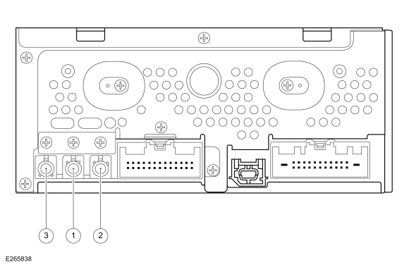
Possible Sources
Visual Inspection and Pre-checks
|
||||||||||||||||
| NOTE: Prior to carrying out diagnostics, it may be beneficial to determine the cause using the Antenna Kit Tool 420-525 (Rotunda part number NUD420-525) or equivalent tool. | ||||||||||||||||
| NOTE: The AM/ FM1 antenna cable is also known as the audio unit antenna cable. | ||||||||||||||||
| A1 CHECK THE VEHICLE FOR THE WI-FI (CELLPHONE INTERFACE) OPTION | ||||||||||||||||
Is the vehicle equipped with the vehicle Wi-Fi (cellphone interface) option (IEPAM)?
|
||||||||||||||||
| A2 CHECK THE AUDIO SYSTEM RECEPTION WITH THE REAR WINDOW DEFROST ACTIVATED AND DEACTIVATED | ||||||||||||||||
Does the poor reception only occur with the rear window defrost activated?
|
||||||||||||||||
| A3 CHECK THE REAR WINDOW DEFROST GRID FOR CORRECT OPERATION | ||||||||||||||||
Does the rear window defrost grid operate correctly?
|
||||||||||||||||
| A4 CHECK THE AUDIO SYSTEM RECEPTION WITH THE ENGINE RUNNING | ||||||||||||||||
Does the poor reception occur only with the engine running?
|
||||||||||||||||
| A5 CHECK THE GENERATOR | ||||||||||||||||
Is the reception OK?
|
||||||||||||||||
| A6 CHECK THE IGNITION CIRCUITS | ||||||||||||||||
Are the ignition components OK?
|
||||||||||||||||
| A7 INSPECT THE AERIAL ANTENNA | ||||||||||||||||
Is the antenna and mount OK?
|
||||||||||||||||
| A8 CHECK FOR VOLTAGE TO THE AM (AMPLITUDE MODULATION) / FM (FREQUENCY MODULATION) 1 ANTENNA AMPLIFIER | ||||||||||||||||
Is the voltage greater than 11 volts?
|
||||||||||||||||
| A9 CHECK THE AM (AMPLITUDE MODULATION) / FM (FREQUENCY MODULATION) 1 ANTENNA AMPLIFIER CIRCUIT FOR A SHORT TO GROUND | ||||||||||||||||
Is the resistance greater than 10,000 ohms?
|
||||||||||||||||
| A10 CHECK THE AM (AMPLITUDE MODULATION) / FM (FREQUENCY MODULATION) 1 ANTENNA AMPLIFIER CIRCUIT FOR AN OPEN | ||||||||||||||||
Is the resistance less than 3 ohms?
|
||||||||||||||||
| A11 CHECK FOR ACM (AUDIO FRONT CONTROL MODULE) FM (FREQUENCY MODULATION) 2 ANTENNA VOLTAGE OUTPUT | ||||||||||||||||
Is the voltage greater than 11 volts?
|
||||||||||||||||
| A12 CHECK FOR VOLTAGE TO THE FM (FREQUENCY MODULATION) 2 ANTENNA AMPLIFIER | ||||||||||||||||
Is the voltage greater than 11 volts?
|
||||||||||||||||
| A13 CHECK THE AM (AMPLITUDE MODULATION) / FM (FREQUENCY MODULATION) 1 ANTENNA CABLE FOR AN OPEN | ||||||||||||||||
Is the resistance less than 3 ohms?
|
||||||||||||||||
| A14 CHECK THE ANTENNA BASE AND MOUNTING SURFACE | ||||||||||||||||
Is audio unit base and mounting free of corrosion?
|
||||||||||||||||
| A15 ISOLATE THE ROOF MOUNTED ANTENNA | ||||||||||||||||
Is the reception OK?
|
||||||||||||||||
| A16 ISOLATE THE AM (AMPLITUDE MODULATION) / FM (FREQUENCY MODULATION) 1 ANTENNA AMPLIFIER | ||||||||||||||||
Is the reception OK?
|
||||||||||||||||
| A17 ISOLATE THE FM (FREQUENCY MODULATION) 2 ANTENNA AMPLIFIER | ||||||||||||||||
Is the reception OK?
|
||||||||||||||||
| A18 CHECK FOR CORRECT ACM (AUDIO FRONT CONTROL MODULE) OPERATION | ||||||||||||||||
Is the concern still present?
|


 FM2 antenna cable core at the FM2 antenna amplifier

 AM/ FM1 antenna cable core at the ACM

 AM/ FM1 antenna cable core at the roof mounted antenna, pin 2
 AM/ FM1 antenna cable core at the ACM

 AM/ FM1 antenna amplifier
 PINPOINT TEST B : SATELLITE RADIO/SIRIUS TRAVEL LINK ™/TRAFFIC ANNOUNCEMENT CONCERN
|
Refer to Wiring Diagrams Cell 130 for schematic and connector information. Normal Operation and Fault Conditions
REFER to: Information and Entertainment System - Component Location (415-00 Information and Entertainment System - General Information - Vehicles With: SYNC 3, Description and Operation). When a satellite radio subscription is active, the ESN of the satellite radio receiver built into the ACM associates with the VIN. Audio Unit Coaxial Cable Connections 
DTC Fault Trigger Conditions
Possible Sources
|
||||||||||||||||||||||||
| NOTE: Prior to carrying out diagnostics, it may be beneficial to determine the cause using the Antenna Kit Tool 420-525 (Rotunda part number NUD420-525) or equivalent tool. | ||||||||||||||||||||||||
| B1 CHECK FOR DTC (DIAGNOSTIC TROUBLE CODE) U1A00:87 | ||||||||||||||||||||||||
Is DTC U1A00:87 present?
|
||||||||||||||||||||||||
| B2 CHECK FOR PROMOTIONAL CHANNEL 1 | ||||||||||||||||||||||||
Does the satellite radio system receive channel 1 with normal sound quality?
|
||||||||||||||||||||||||
| B3 VERIFY AN ACTIVE SUBSCRIPTION | ||||||||||||||||||||||||
Does the display indicate the subscription has expired?
|
||||||||||||||||||||||||
| B4 CHECK THE VEHICLE SERVICE HISTORY FOR ACM (AUDIO FRONT CONTROL MODULE) REPLACEMENT | ||||||||||||||||||||||||
Does the vehicle service history indicate the ACM was recently replaced?
|
||||||||||||||||||||||||
| B5 VERIFY THE VIN (VEHICLE IDENTIFICATION NUMBER) AND THE ESN (ELECTRONIC SERIAL NUMBER) ON FILE MATCHES THE VIN (VEHICLE IDENTIFICATION NUMBER) AND THE ESN (ELECTRONIC SERIAL NUMBER) FROM THE VEHICLE | ||||||||||||||||||||||||
Does the VIN and the ESN on the SIRIUS customer file match the ESN and VIN retrieved from the vehicle?
|
||||||||||||||||||||||||
| B6 VERIFY THE VIN (VEHICLE IDENTIFICATION NUMBER) AND THE ESN (ELECTRONIC SERIAL NUMBER) ON FILE MATCHES THE VIN (VEHICLE IDENTIFICATION NUMBER) AND THE ESN (ELECTRONIC SERIAL NUMBER) FROM THE VEHICLE | ||||||||||||||||||||||||
Does the satellite radio system receive multiple channels with normal sound quality?
|
||||||||||||||||||||||||
| B7 SEND THE SIRIUS ACTIVATION SIGNAL AND RECHECK SIRIUS TRAVEL LINK™ FOR CORRECT OPERATION | ||||||||||||||||||||||||
Does the SIRIUS Travel Link™ operate correctly?
|
||||||||||||||||||||||||
| B8 ALLOW THE CATEGORIES TO UPDATE AND THEN CHECK SIRIUS TRAVEL LINK™ FOR CORRECT OPERATION | ||||||||||||||||||||||||
|
NOTE: The frequency of category updates varies and depends on the category and the SIRIUS infrastructure data load.
Does SIRIUS Travel Link™ operate correctly?
|
||||||||||||||||||||||||
| B9 CHECK FOR CORRECT ACM (AUDIO FRONT CONTROL MODULE) OUTPUT VOLTAGE TO THE SATELLITE RADIO ANTENNA CABLE | ||||||||||||||||||||||||
Is the voltage between 4.7 and 5.8 volts?
|
||||||||||||||||||||||||
| B10 CHECK FOR VOLTAGE TO THE GPS (GLOBAL POSITIONING SYSTEM) /SATELLITE RADIO ANTENNA | ||||||||||||||||||||||||
Is the voltage between 4.7 and 5.8 volts?
|
||||||||||||||||||||||||
| B11 ISOLATE THE GPS (GLOBAL POSITIONING SYSTEM) /SATELLITE RADIO ANTENNA SPLITTER CABLE | ||||||||||||||||||||||||
Does the system in question operate correctly?
|
||||||||||||||||||||||||
| B12 CHECK THE ANTENNA BASE AND MOUNTING SURFACE | ||||||||||||||||||||||||
Is antenna base and mounting free of corrosion?
|
||||||||||||||||||||||||
| B13 VERIFY THE COMPASS OPERATES CORRECTLY | ||||||||||||||||||||||||
Does the compass operate correctly?
|
||||||||||||||||||||||||
| B14 ISOLATE THE GPS (GLOBAL POSITIONING SYSTEM) /SATELLITE RADIO ANTENNA | ||||||||||||||||||||||||
Does the system in question operate correctly?
|
||||||||||||||||||||||||
| B15 CHECK THE SERIAL DATA CIRCUITS FOR A SHORT TO GROUND | ||||||||||||||||||||||||
Are the resistances greater than 10,000 ohms?
|
||||||||||||||||||||||||
| B16 CHECK THE SERIAL DATA CIRCUITS FOR A SHORT TO VOLTAGE | ||||||||||||||||||||||||
Is any voltage present?
|
||||||||||||||||||||||||
| B17 CHECK THE SERIAL DATA CIRCUITS FOR A SHORT TOGETHER | ||||||||||||||||||||||||
Is the resistance greater than 10,000 ohms?
|
||||||||||||||||||||||||
| B18 CHECK THE SERIAL DATA CIRCUITS FOR AN OPEN | ||||||||||||||||||||||||
Are the resistances less than 3 ohms?
|
||||||||||||||||||||||||
| B19 CHECK FOR CORRECT ACM (AUDIO FRONT CONTROL MODULE) OPERATION | ||||||||||||||||||||||||
Is the concern still present?
|
||||||||||||||||||||||||
| B20 CHECK FOR CORRECT APIM (SYNC MODULE) OPERATION | ||||||||||||||||||||||||
Is the concern still present?
|

 GPS antenna cable core at the roof mounted antenna, pin 1


 Click here to access Guided Routine (APIM).
 Internet Explorer version 11 or greater is required to perform this Pinpoint Test.
 PINPOINT TEST C : NO SOUND FROM ALL SPEAKERS
|
Refer to Wiring Diagrams Cell 130 for schematic and connector information. Normal Operation and Fault Conditions
REFER to: Information and Entertainment System - Component Location (415-00 Information and Entertainment System - General Information - Vehicles With: SYNC 3, Description and Operation). A short to ground or voltage in the circuitry to one of the speakers may cause multiple speakers to lose sound due to the built-in overload protection feature of the ACM or the DSP. In this case, a speaker fault DTC sets. DTC Fault Trigger Conditions
Possible Sources
|
|||||||||||||||||||||||||||||||||||||||||||||
| C1 VERIFY THE ACM (AUDIO FRONT CONTROL MODULE) PASSES THE NETWORK TEST | |||||||||||||||||||||||||||||||||||||||||||||
Does the ACM pass the network test?
|
|||||||||||||||||||||||||||||||||||||||||||||
| C2 VERIFY THE APIM (SYNC MODULE) PASSES THE NETWORK TEST | |||||||||||||||||||||||||||||||||||||||||||||
Does the APIM pass the network test?
|
|||||||||||||||||||||||||||||||||||||||||||||
| C3 VERIFY THE DSP (AUDIO DIGITAL SIGNAL PROCESSING MODULE) PASSES THE NETWORK TEST | |||||||||||||||||||||||||||||||||||||||||||||
Does the DSP pass the network test?
|
|||||||||||||||||||||||||||||||||||||||||||||
| C4 CHECK FOR APIM (SYNC MODULE) DIAGNOSTIC TROUBLE CODES (DTCS) | |||||||||||||||||||||||||||||||||||||||||||||
Are any Diagnostic Trouble Codes (DTCs) present?
|
|||||||||||||||||||||||||||||||||||||||||||||
| C5 CHECK FOR ACM (AUDIO FRONT CONTROL MODULE) DIAGNOSTIC TROUBLE CODES (DTCS) | |||||||||||||||||||||||||||||||||||||||||||||
Are any Diagnostic Trouble Codes (DTCs) present?
|
|||||||||||||||||||||||||||||||||||||||||||||
| C6 CHECK FOR DSP (AUDIO DIGITAL SIGNAL PROCESSING MODULE) SPEAKER-RELATED DIAGNOSTIC TROUBLE CODES (DTCS) | |||||||||||||||||||||||||||||||||||||||||||||
Are any speaker-related Diagnostic Trouble Codes (DTCs) present?
|
|||||||||||||||||||||||||||||||||||||||||||||
| C7 CHECK THE DSP (AUDIO DIGITAL SIGNAL PROCESSING MODULE) ENABLE CIRCUIT FOR CORRECT VOLTAGE | |||||||||||||||||||||||||||||||||||||||||||||
Is the voltage between 3.5 and 7 volts?
|
|||||||||||||||||||||||||||||||||||||||||||||
| C8 CHECK THE DSP (AUDIO DIGITAL SIGNAL PROCESSING MODULE) ENABLE CIRCUIT FOR A SHORT TO GROUND | |||||||||||||||||||||||||||||||||||||||||||||
Is the resistance greater than 10,000 ohms?
|
|||||||||||||||||||||||||||||||||||||||||||||
| C9 CHECK THE DSP (AUDIO DIGITAL SIGNAL PROCESSING MODULE) ENABLE CIRCUIT FOR A SHORT TO VOLTAGE | |||||||||||||||||||||||||||||||||||||||||||||
Is any voltage present?
|
|||||||||||||||||||||||||||||||||||||||||||||
| C10 CHECK THE DSP (AUDIO DIGITAL SIGNAL PROCESSING MODULE) ENABLE CIRCUIT FOR AN OPEN | |||||||||||||||||||||||||||||||||||||||||||||
Is the resistance less than 3 ohms?
|
|||||||||||||||||||||||||||||||||||||||||||||
| C11 CHECK THE ACM (AUDIO FRONT CONTROL MODULE) CONFIGURATION | |||||||||||||||||||||||||||||||||||||||||||||
Is sound heard from all of the speakers?
|
|||||||||||||||||||||||||||||||||||||||||||||
| C12 CHECK THE DSP (AUDIO DIGITAL SIGNAL PROCESSING MODULE) CONFIGURATION | |||||||||||||||||||||||||||||||||||||||||||||
Is sound heard from all of the speakers?
|
|||||||||||||||||||||||||||||||||||||||||||||
| C13 CHECK THE FRONT AUTOMOBILE AUDIO BUS (A2B) CABLE | |||||||||||||||||||||||||||||||||||||||||||||
Is sound heard from all of the speakers?
|
|||||||||||||||||||||||||||||||||||||||||||||
| C14 CHECK THE REAR AUTOMOBILE AUDIO BUS (A2B) CABLE | |||||||||||||||||||||||||||||||||||||||||||||
Is sound heard from all of the speakers?
|
|||||||||||||||||||||||||||||||||||||||||||||
| C15 CHECK FOR CORRECT DSP (AUDIO DIGITAL SIGNAL PROCESSING MODULE) OPERATION | |||||||||||||||||||||||||||||||||||||||||||||
Is the concern still present?
|
|||||||||||||||||||||||||||||||||||||||||||||
| C16 CHECK FOR CORRECT ACM (AUDIO FRONT CONTROL MODULE) OPERATION | |||||||||||||||||||||||||||||||||||||||||||||
Is the concern still present?
|


 PINPOINT TEST D : POOR SOUND QUALITY OR DISTORTED SOUND FROM ONE OR MORE SPEAKERS (NOT ALL SPEAKERS)
|
Normal Operation and Fault Conditions
REFER to: Information and Entertainment System - Component Location (415-00 Information and Entertainment System - General Information - Vehicles With: SYNC 3, Description and Operation). Audio signals are sent to the speakers in the form of AC voltage, resulting in clear audio output. Possible Sources
Visual Inspection and Pre-checks
|
||||
| D1 ISOLATE THE ZONE | ||||
Does applying pressure to a trim panel reduce or eliminate the noise?
|
||||
| D2 REMOVE AND INSPECT BEHIND/UNDERNEATH THE SUSPECT TRIM PANEL | ||||
Is the source of the noise located?
|
||||
| D3 CHECK THE SUSPECT SPEAKER FOR WATER INTRUSION | ||||
Are any watermarks present on the speaker?
|
||||
| D4 ISOLATE THE SUSPECT SPEAKER TO VERIFY NOISE | ||||
Is the noise still present in the suspect speaker?
|
 PINPOINT TEST E : THE SPEED COMPENSATED VOLUME IS INOPERATIVE
|
Normal Operation and Fault Conditions
REFER to: Information and Entertainment System - System Operation and Component Description (415-00 Information and Entertainment System - General Information - Vehicles With: SYNC 3, Description and Operation). Possible Sources
|
||||
| E1 CHECK THE SPEED COMPENSATED VOLUME SETTING | ||||
|
NOTE: Refer to the Owner Literature to access the speed compensated volume settings.
Does the volume remain constant with the speed compensated volume turned off, and increase and decrease with vehicle speed with the speed compensated volume set to maximum?
|
||||
| E2 CHECK FOR COMMUNICATION DIAGNOSTIC TROUBLE CODES (DTCS) | ||||
Are any Diagnostic Trouble Codes (DTCs) present?
|
||||
| E3 CARRY OUT PMI (PROGRAMMABLE MODULE INSTALLATION) FOR THE SUSPECT MODULE | ||||
Does the speed compensated volume feature operate?
|
||||
| E4 CHECK FOR CORRECT DSP (AUDIO DIGITAL SIGNAL PROCESSING MODULE) OPERATION | ||||
Is the concern still present?
|
||||
| E5 CHECK FOR CORRECT ACM (AUDIO FRONT CONTROL MODULE) OPERATION | ||||
Is the concern still present?
|
 PINPOINT TEST F : ONE OR MORE SPEAKER IS INOPERATIVE - ACM (AUDIO FRONT CONTROL MODULE)
CONTROLLED - EXCEPT 12 SPEAKER SYSTEM
PINPOINT TEST F : ONE OR MORE SPEAKER IS INOPERATIVE - ACM (AUDIO FRONT CONTROL MODULE)
CONTROLLED - EXCEPT 12 SPEAKER SYSTEM|
Refer to Wiring Diagrams Cell 130 for schematic and connector information. Normal Operation and Fault Conditions
REFER to: Information and Entertainment System - Component Location (415-00 Information and Entertainment System - General Information - Vehicles With: SYNC 3, Description and Operation). DTC Fault Trigger Conditions
Possible Sources
|
|||||||||||||||||||||||||||||||||||||||||||||||||||||||||||||||||||||||||||||||||||||||||||||||||||||||
| NOTE: If equipped with door tweeter speakers, the door tweeter speaker receives the signal from the corresponding door woofer speaker. If a concern exists with both speakers, retest the system with the tweeter speaker disconnected to determine if the tweeter speaker is the cause of the concern. | |||||||||||||||||||||||||||||||||||||||||||||||||||||||||||||||||||||||||||||||||||||||||||||||||||||||
| F1 CHECK THE AUDIO CIRCUITS TO THE SPEAKER FOR A SHORT TO GROUND | |||||||||||||||||||||||||||||||||||||||||||||||||||||||||||||||||||||||||||||||||||||||||||||||||||||||
|
NOTE: If a concern exist with a door speaker, the door woofer speaker and the corresponding door tweeter speaker (if equipped) must be disconnected for correct test results.
Are the resistances greater than 10,000 ohms?
|
|||||||||||||||||||||||||||||||||||||||||||||||||||||||||||||||||||||||||||||||||||||||||||||||||||||||
| F2 CHECK THE AUDIO CIRCUITS TO THE SPEAKER FOR A SHORT TO VOLTAGE | |||||||||||||||||||||||||||||||||||||||||||||||||||||||||||||||||||||||||||||||||||||||||||||||||||||||
Is any voltage present?
|
|||||||||||||||||||||||||||||||||||||||||||||||||||||||||||||||||||||||||||||||||||||||||||||||||||||||
| F3 CHECK THE AUDIO CIRCUITS TO THE SPEAKER FOR A SHORT TOGETHER | |||||||||||||||||||||||||||||||||||||||||||||||||||||||||||||||||||||||||||||||||||||||||||||||||||||||
Are the resistances greater than 10,000 ohms?
|
|||||||||||||||||||||||||||||||||||||||||||||||||||||||||||||||||||||||||||||||||||||||||||||||||||||||
| F4 CHECK THE AUDIO CIRCUITS TO THE SPEAKER FOR AN OPEN | |||||||||||||||||||||||||||||||||||||||||||||||||||||||||||||||||||||||||||||||||||||||||||||||||||||||
Are the resistances less than 3 ohms?
|
|||||||||||||||||||||||||||||||||||||||||||||||||||||||||||||||||||||||||||||||||||||||||||||||||||||||
| F5 CHECK THE AUDIO SIGNAL TO THE SUSPECT SPEAKER | |||||||||||||||||||||||||||||||||||||||||||||||||||||||||||||||||||||||||||||||||||||||||||||||||||||||
|
NOTE: If a concern exist with a door tweeter speaker, the corresponding door woofer speaker must be connected for correct test results.
Is a fluctuating AC voltage present?
|
|||||||||||||||||||||||||||||||||||||||||||||||||||||||||||||||||||||||||||||||||||||||||||||||||||||||
| F6 CHECK FOR CORRECT ACM (AUDIO FRONT CONTROL MODULE) OPERATION | |||||||||||||||||||||||||||||||||||||||||||||||||||||||||||||||||||||||||||||||||||||||||||||||||||||||
Is the concern still present?
|


 PINPOINT TEST G : ONE OR BOTH SUBWOOFER SPEAKERS ARE INOPERATIVE
|
Refer to Wiring Diagrams Cell 130 for schematic and connector information. Normal Operation and Fault Conditions
REFER to: Information and Entertainment System - Component Location (415-00 Information and Entertainment System - General Information - Vehicles With: SYNC 3, Description and Operation). DTC Fault Trigger Conditions
Possible Sources
Visual Inspection and Pre-checks
|
||||||||||||||||||||||
| G1 CHECK FOR VOLTAGE TO THE SUBWOOFER AMPLIFIER | ||||||||||||||||||||||
Is the voltage greater than 11 volts?
|
||||||||||||||||||||||
| G2 CHECK THE SUBWOOFER AMPLIFIER VOLTAGE SUPPLY CIRCUIT FOR AN OPEN | ||||||||||||||||||||||
Is the resistance less than 3 ohms?
|
||||||||||||||||||||||
| G3 CHECK THE SUBWOOFER AMPLIFIER GROUND CIRCUIT FOR AN OPEN | ||||||||||||||||||||||
Is the voltage greater than 11 volts?
|
||||||||||||||||||||||
| G4 CHECK THE AMPLIFIER ENABLE CIRCUIT FOR CORRECT VOLTAGE | ||||||||||||||||||||||
Is the voltage between 3.5 and 7 volts?
|
||||||||||||||||||||||
| G5 CHECK THE AMPLIFIER ENABLE CIRCUIT FOR A SHORT TO GROUND | ||||||||||||||||||||||
Is the resistance greater than 10,000 ohms?
|
||||||||||||||||||||||
| G6 CHECK THE AMPLIFIER ENABLE CIRCUIT FOR A SHORT TO VOLTAGE | ||||||||||||||||||||||
Is any voltage present?
|
||||||||||||||||||||||
| G7 CHECK THE AMPLIFIER ENABLE CIRCUIT FOR AN OPEN | ||||||||||||||||||||||
Is the resistance less than 3 ohms?
|
||||||||||||||||||||||
| G8 CHECK THE AUDIO CIRCUITS TO THE AMPLIFIER FOR A SHORT TO GROUND | ||||||||||||||||||||||
Are the resistances greater than 10,000 ohms?
|
||||||||||||||||||||||
| G9 CHECK THE AUDIO CIRCUITS TO THE AMPLIFIER FOR A SHORT TO VOLTAGE | ||||||||||||||||||||||
Is any voltage present?
|
||||||||||||||||||||||
| G10 CHECK THE AUDIO CIRCUITS TO THE AMPLIFIER FOR A SHORT TOGETHER | ||||||||||||||||||||||
Is the resistance greater than 10,000 ohms?
|
||||||||||||||||||||||
| G11 CHECK THE AUDIO CIRCUITS TO THE AMPLIFIER FOR AN OPEN | ||||||||||||||||||||||
Are the resistances less than 3 ohms?
|
||||||||||||||||||||||
| G12 CHECK THE SUBWOOFER AUDIO SIGNAL TO THE SUBWOOFER AMPLIFIER | ||||||||||||||||||||||
Is a fluctuating AC voltage present?
|
||||||||||||||||||||||
| G13 CHECK THE AUDIO CIRCUITS TO THE SUBWOOFER SPEAKER FOR A SHORT TO GROUND | ||||||||||||||||||||||
Are the resistances greater than 10,000 ohms?
|
||||||||||||||||||||||
| G14 CHECK THE AUDIO CIRCUITS TO THE SUBWOOFER SPEAKER FOR A SHORT TO VOLTAGE | ||||||||||||||||||||||
Is any voltage present?
|
||||||||||||||||||||||
| G15 CHECK THE AUDIO CIRCUITS TO THE SUBWOOFER SPEAKER FOR A SHORT TOGETHER | ||||||||||||||||||||||
Are the resistances greater than 10,000 ohms?
|
||||||||||||||||||||||
| G16 CHECK THE AUDIO CIRCUITS TO THE SUBWOOFER SPEAKER FOR AN OPEN | ||||||||||||||||||||||
Are the resistances less than 3 ohms?
|
||||||||||||||||||||||
| G17 CHECK THE AUDIO SIGNAL TO THE SUBWOOFER SPEAKER | ||||||||||||||||||||||
Is a fluctuating AC voltage present?
|
||||||||||||||||||||||
| G18 CHECK FOR CORRECT BCM (BODY CONTROL MODULE) OPERATION | ||||||||||||||||||||||
Is the concern still present?
|
||||||||||||||||||||||
| G19 CHECK FOR CORRECT ACM (AUDIO FRONT CONTROL MODULE) OPERATION | ||||||||||||||||||||||
Is the concern still present?
|


 PINPOINT TEST H : ONE OR MORE SPEAKER IS INOPERATIVE - ACM (AUDIO FRONT CONTROL MODULE)
CONTROLLED - 12 SPEAKER SYSTEM
PINPOINT TEST H : ONE OR MORE SPEAKER IS INOPERATIVE - ACM (AUDIO FRONT CONTROL MODULE)
CONTROLLED - 12 SPEAKER SYSTEM|
Refer to Wiring Diagrams Cell 130 for schematic and connector information. Normal Operation and Fault Conditions
REFER to: Information and Entertainment System - Component Location (415-00 Information and Entertainment System - General Information - Vehicles With: SYNC 3, Description and Operation). DTC Fault Trigger Conditions
Possible Sources
|
|||||||||||||||||||||||||||||||||||||||||||||||||||
| H1 CHECK THE AUDIO CIRCUITS TO THE SPEAKER FOR A SHORT TO GROUND | |||||||||||||||||||||||||||||||||||||||||||||||||||
Are the resistances greater than 10,000 ohms?
|
|||||||||||||||||||||||||||||||||||||||||||||||||||
| H2 CHECK THE AUDIO CIRCUITS TO THE SPEAKER FOR A SHORT TO VOLTAGE | |||||||||||||||||||||||||||||||||||||||||||||||||||
Is any voltage present?
|
|||||||||||||||||||||||||||||||||||||||||||||||||||
| H3 CHECK THE AUDIO CIRCUITS TO THE SPEAKER FOR A SHORT TOGETHER | |||||||||||||||||||||||||||||||||||||||||||||||||||
Are the resistances greater than 10,000 ohms?
|
|||||||||||||||||||||||||||||||||||||||||||||||||||
| H4 CHECK THE AUDIO CIRCUITS TO THE SPEAKER FOR AN OPEN | |||||||||||||||||||||||||||||||||||||||||||||||||||
Are the resistances less than 3 ohms?
|
|||||||||||||||||||||||||||||||||||||||||||||||||||
| H5 CHECK THE AUDIO SIGNAL TO THE SUSPECT SPEAKER | |||||||||||||||||||||||||||||||||||||||||||||||||||
Is a fluctuating AC voltage present?
|
|||||||||||||||||||||||||||||||||||||||||||||||||||
| H6 CHECK FOR CORRECT ACM (AUDIO FRONT CONTROL MODULE) OPERATION | |||||||||||||||||||||||||||||||||||||||||||||||||||
Is the concern still present?
|


 PINPOINT TEST I : ONE OR MORE SPEAKER IS INOPERATIVE - DSP (AUDIO DIGITAL SIGNAL PROCESSING MODULE)
CONTROLLED SPEAKERS
PINPOINT TEST I : ONE OR MORE SPEAKER IS INOPERATIVE - DSP (AUDIO DIGITAL SIGNAL PROCESSING MODULE)
CONTROLLED SPEAKERS|
Refer to Wiring Diagrams Cell 130 for schematic and connector information. Normal Operation and Fault Conditions
REFER to: Information and Entertainment System - Component Location (415-00 Information and Entertainment System - General Information - Vehicles With: SYNC 3, Description and Operation). DTC Fault Trigger Conditions
Possible Sources
|
||||||||||||||||||||||||||||||||||||||||||||||||||||||||||||||||||||||||||||
| NOTE: The rear door tweeter speakers receive the signal from the corresponding door woofer speaker. If a concern exists with both speakers, retest the system with the tweeter speaker disconnected to determine if the tweeter speaker is the cause of the concern. | ||||||||||||||||||||||||||||||||||||||||||||||||||||||||||||||||||||||||||||
| I1 CHECK FOR ACM (AUDIO FRONT CONTROL MODULE) DIAGNOSTIC TROUBLE CODES (DTCS) | ||||||||||||||||||||||||||||||||||||||||||||||||||||||||||||||||||||||||||||
Are any Diagnostic Trouble Codes (DTCs) present?
|
||||||||||||||||||||||||||||||||||||||||||||||||||||||||||||||||||||||||||||
| I2 CHECK THE AUDIO CIRCUITS TO THE SPEAKER FOR A SHORT TO GROUND | ||||||||||||||||||||||||||||||||||||||||||||||||||||||||||||||||||||||||||||
|
NOTE: If a concern exist with a rear door speaker, the rear door woofer speaker and the corresponding rear door tweeter speaker must be disconnected for correct test results.
Are the resistances greater than 10,000 ohms?
|
||||||||||||||||||||||||||||||||||||||||||||||||||||||||||||||||||||||||||||
| I3 CHECK THE AUDIO CIRCUITS TO THE SPEAKER FOR A SHORT TO VOLTAGE | ||||||||||||||||||||||||||||||||||||||||||||||||||||||||||||||||||||||||||||
Is any voltage present?
|
||||||||||||||||||||||||||||||||||||||||||||||||||||||||||||||||||||||||||||
| I4 CHECK THE AUDIO CIRCUITS TO THE SPEAKER FOR A SHORT TOGETHER | ||||||||||||||||||||||||||||||||||||||||||||||||||||||||||||||||||||||||||||
Are the resistances greater than 10,000 ohms?
|
||||||||||||||||||||||||||||||||||||||||||||||||||||||||||||||||||||||||||||
| I5 CHECK THE AUDIO CIRCUITS TO THE SPEAKER FOR AN OPEN | ||||||||||||||||||||||||||||||||||||||||||||||||||||||||||||||||||||||||||||
Are the resistances less than 3 ohms?
|
||||||||||||||||||||||||||||||||||||||||||||||||||||||||||||||||||||||||||||
| I6 CHECK THE AUDIO SIGNAL TO THE SUSPECT SPEAKER | ||||||||||||||||||||||||||||||||||||||||||||||||||||||||||||||||||||||||||||
|
NOTE: For a rear door tweeter speaker concern, make sure the corresponding rear door woofer speaker is connected.
Is a fluctuating AC voltage present?
|
||||||||||||||||||||||||||||||||||||||||||||||||||||||||||||||||||||||||||||
| I7 CHECK FOR CORRECT DSP (AUDIO DIGITAL SIGNAL PROCESSING MODULE) OPERATION | ||||||||||||||||||||||||||||||||||||||||||||||||||||||||||||||||||||||||||||
Is the concern still present?
|


 PINPOINT TEST J : THE AUDIO/SYNC SYSTEM DOES NOT OPERATE CORRECTLY FROM THE FCIM (FRONT CONTROLS INTERFACE MODULE)
|
Normal Operation and Fault Conditions
REFER to: Information and Entertainment System - System Operation and Component Description (415-00 Information and Entertainment System - General Information - Vehicles With: SYNC 3, Description and Operation). Possible Sources
|
||||
| J1 VERIFY THE ACM (AUDIO FRONT CONTROL MODULE) , THE APIM (SYNC MODULE) AND THE FCIM (FRONT CONTROLS INTERFACE MODULE) PASS THE NETWORK TEST | ||||
Does the ACM, the APIM and the FCIM pass the network test?
|
||||
| J2 CHECK FOR ACM (AUDIO FRONT CONTROL MODULE) DIAGNOSTIC TROUBLE CODES (DTCS) | ||||
Are any Diagnostic Trouble Codes (DTCs) present?
|
||||
| J3 CHECK FOR APIM (SYNC MODULE) DIAGNOSTIC TROUBLE CODES (DTCS) | ||||
Are any Diagnostic Trouble Codes (DTCs) present?
|
||||
| J4 CHECK FOR FCIM (FRONT CONTROLS INTERFACE MODULE) DIAGNOSTIC TROUBLE CODES (DTCS) | ||||
Are any Diagnostic Trouble Codes (DTCs) present?
|
||||
| J5 CHECK FOR CORRECT FCIM (FRONT CONTROLS INTERFACE MODULE) OPERATION | ||||
Is the concern still present?
|
 PINPOINT TEST K : ONE OR MORE AUDIO/SYNC STEERING WHEEL CONTROL BUTTON IS INOPERATIVE
|
Refer to Wiring Diagrams Cell 130 for schematic and connector information. Normal Operation and Fault Conditions
REFER to: Information and Entertainment System - System Operation and Component Description (415-00 Information and Entertainment System - General Information - Vehicles With: SYNC 3, Description and Operation). DTC Fault Trigger Conditions
Possible Sources
|
||||||||||||||||||||||||||||||||||
| K1 CHECK FOR VOLTAGE TO THE STEERING WHEEL SWITCH | ||||||||||||||||||||||||||||||||||
Are the voltages approximately 5 volts?
|
||||||||||||||||||||||||||||||||||
| K2 CHECK THE STEERING WHEEL HARNESS | ||||||||||||||||||||||||||||||||||
Are the voltages approximately 5 volts?
|
||||||||||||||||||||||||||||||||||
| K3 CHECK THE CLOCKSPRING FOR AN OPEN | ||||||||||||||||||||||||||||||||||
Are the resistances less than 3 ohms?
|
||||||||||||||||||||||||||||||||||
| K4 CHECK FOR CORRECT SCCM (STEERING COLUMN CONTROL MODULE) OPERATION | ||||||||||||||||||||||||||||||||||
Is the concern still present?
|


 Upper Clockspring C218B, pin 6 (component side)

 Upper Clockspring C218B, pin 16 (component side)
 Upper Clockspring C218B, pin 7 (component side)

 Upper Clockspring C218B, pin 16 (component side)
 Upper Clockspring C218B, pin 14 (component side)

 Upper Clockspring C218B, pin 8 (component side)
 Upper Clockspring C218B, pin 15 (component side)

 Upper Clockspring C218B, pin 8 (component side)
 Upper Clockspring C218B, pin 6 (component side)

 Lower Clockspring C218C, pin 5 (component side)
 Upper Clockspring C218B, pin 7 (component side)

 Lower Clockspring C218C, pin 7 (component side)
 Upper Clockspring C218B, pin 8 (component side)

 Lower Clockspring C218C, pin 9 (component side)
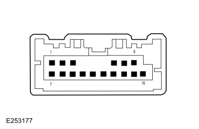 Upper Clockspring C218B, pin 14 (component side)

 Lower Clockspring C218C, pin 6 (component side)
 Upper Clockspring C218B, pin 15 (component side)

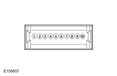 Lower Clockspring C218C, pin 8 (component side)
 Upper Clockspring C218B, pin 16 (component side)

 Lower Clockspring C218C, pin 10 (component side)
 PINPOINT TEST L : THE DISPLAY UNIT IS INOPERATIVE OR DOES NOT OPERATE CORRECTLY - NON-TOUCHSCREEN
|
NOTE: The display unit calibrates after each ignition cycle. Touching the display during an ignition cycle may cause the touchscreen to be inoperative. Refer to Wiring Diagrams Cell 130 for schematic and connector information. Normal Operation and Fault Conditions
REFER to: Information and Entertainment System - System Operation and Component Description (415-00 Information and Entertainment System - General Information - Vehicles With: SYNC 3, Description and Operation). DTC Fault Trigger Conditions
Possible Sources
|
|||||||||||||||||||||
| NOTE: Prior to carrying out diagnostics, it may be beneficial to determine the cause using the Circuit Tester and LVDS Adapter Kit 420-912 (Rotunda part number NUD420-912) or equivalent tool. | |||||||||||||||||||||
| L1 CHECK FOR A NETWORK CONCERN | |||||||||||||||||||||
|
NOTE: The display screen is blank if a concern with the HS-CAN3 is present.
Does the ACM and the APIM pass the network test?
|
|||||||||||||||||||||
| L2 CHECK FOR CAN (CONTROLLER AREA NETWORK) COMMUNICATION AND CONFIGURATION DIAGNOSTIC TROUBLE CODES (DTCS) | |||||||||||||||||||||
Are any CAN communication or configuration related Diagnostic Trouble Codes (DTCs) present?
|
|||||||||||||||||||||
| L3 CHECK FOR ACM (AUDIO FRONT CONTROL MODULE) DIAGNOSTIC TROUBLE CODES (DTCS) | |||||||||||||||||||||
Are any Diagnostic Trouble Codes (DTCs) present?
|
|||||||||||||||||||||
| L4 CHECK FOR APIM (SYNC MODULE) DIAGNOSTIC TROUBLE CODES (DTCS) | |||||||||||||||||||||
Are any Diagnostic Trouble Codes (DTCs) present?
|
|||||||||||||||||||||
| L5 CHECK THE LVDS (LOW VOLTAGE DIFFERENTIAL SIGNALING) CABLE FOR AN OPEN | |||||||||||||||||||||
|
NOTICE: Use the male Flex Probe 300-08057 (0.5 mm) or equivalent. Failure to use the correct probe may damage the LVDS cable.
Are the resistances less than 3 ohms?
|
|||||||||||||||||||||
| L6 CHECK FOR CORRECT VOLTAGE TO THE DISPLAY UNIT | |||||||||||||||||||||
|
NOTICE: Use the male Flex Probe 300-08057 (0.5 mm) or equivalent. Failure to use the correct probe may damage the LVDS cable.
Is the voltage greater than 11 volts?
|
|||||||||||||||||||||
| L7 TEMPORARILY REMOVE THE POWER FROM THE APIM (SYNC MODULE) AND RECHECK THE SYSTEM OPERATION | |||||||||||||||||||||
Is the concern still present?
|
|||||||||||||||||||||
| L8 CHECK FOR CORRECT APIM (SYNC MODULE) OPERATION | |||||||||||||||||||||
Is the concern still present?
|


 Click here to access Guided Routine (APIM).
 Internet Explorer version 11 or greater is required to perform this Pinpoint Test.
 PINPOINT TEST M : THE DISPLAY UNIT IS INOPERATIVE OR DOES NOT OPERATE CORRECTLY - TOUCHSCREEN
|
NOTE: The display unit calibrates after each ignition cycle. Touching the display during an ignition cycle may cause the touchscreen to be inoperative. Refer to Wiring Diagrams Cell 130 for schematic and connector information. Normal Operation and Fault Conditions
REFER to: Information and Entertainment System - System Operation and Component Description (415-00 Information and Entertainment System - General Information - Vehicles With: SYNC 3, Description and Operation). DTC Fault Trigger Conditions
Possible Sources
|
|||||||||||||||||||||
| NOTE: Prior to carrying out diagnostics, it may be beneficial to determine the cause using the Circuit Tester and LVDS Adapter Kit 420-912 (Rotunda part number NUD420-912) or equivalent tool. | |||||||||||||||||||||
| M1 CHECK FOR A NETWORK CONCERN | |||||||||||||||||||||
|
NOTE: The display screen is blank if a concern with the HS-CAN3 is present.
Does the ACM and the APIM pass the network test?
|
|||||||||||||||||||||
| M2 CHECK FOR APIM (SYNC MODULE) DIAGNOSTIC TROUBLE CODES (DTCS) | |||||||||||||||||||||
Are any Diagnostic Trouble Codes (DTCs) present?
|
|||||||||||||||||||||
| M3 CHECK FOR CAN (CONTROLLER AREA NETWORK) COMMUNICATION AND CONFIGURATION DIAGNOSTIC TROUBLE CODES (DTCS) | |||||||||||||||||||||
Are any CAN communication or configuration related Diagnostic Trouble Codes (DTCs) present?
|
|||||||||||||||||||||
| M4 CHECK FOR ACM (AUDIO FRONT CONTROL MODULE) DIAGNOSTIC TROUBLE CODES (DTCS) | |||||||||||||||||||||
Are any Diagnostic Trouble Codes (DTCs) present?
|
|||||||||||||||||||||
| M5 REBOOT THE APIM (SYNC MODULE) AND RECHECK THE SYSTEM OPERATION | |||||||||||||||||||||
Is the concern still present?
|
|||||||||||||||||||||
| M6 ACCESS THE BEZEL DIAGNOSTICS | |||||||||||||||||||||
Does the touchscreen enter the "RGB Pixel Test" mode?
|
|||||||||||||||||||||
| M7 INSPECT THE DISPLAY FOR CRACKS | |||||||||||||||||||||
Are any cracks present on the display?
|
|||||||||||||||||||||
| M8 CONFIRM THE TOUCH RESPONSE | |||||||||||||||||||||
Does the display respond correctly and respond in a timely manner to each touch point?
|
|||||||||||||||||||||
| M9 INSPECT THE TOUCHSCREEN DISPLAY IMAGE CLARITY | |||||||||||||||||||||
Is the image quality concern present when using the "RGB Pixel Test" and "Display Test Pattern" functions?
|
|||||||||||||||||||||
| M10 CHECK IF THE IPC (INSTRUMENT PANEL CLUSTER) POWERS UP | |||||||||||||||||||||
Does the IPC power up when the ignition is cycled on?
|
|||||||||||||||||||||
| M11 CHECK THE LVDS (LOW VOLTAGE DIFFERENTIAL SIGNALING) CABLE FOR AN OPEN | |||||||||||||||||||||
|
NOTICE: Use the male Flex Probe 300-08057 (0.5 mm) or equivalent. Failure to use the correct probe may damage the LVDS cable.
Are the resistances less than 3 ohms?
|
|||||||||||||||||||||
| M12 CHECK FOR CORRECT VOLTAGE TO THE DISPLAY UNIT | |||||||||||||||||||||
|
NOTICE: Use the male Flex Probe 300-08057 (0.5 mm) or equivalent. Failure to use the correct probe may damage the LVDS cable.
Is the voltage greater than 11 volts?
|
|||||||||||||||||||||
| M13 TEMPORARILY REMOVE THE POWER FROM THE APIM (SYNC MODULE) AND RECHECK THE SYSTEM OPERATION | |||||||||||||||||||||
Is the concern still present?
|
|||||||||||||||||||||
| M14 CHECK FOR CORRECT APIM (SYNC MODULE) OPERATION | |||||||||||||||||||||
Is the concern still present?
|
 Click here to access Guided Routine (FDIM).
 Internet Explorer version 11 or greater is required to perform this Pinpoint Test.


 Click here to access Guided Routine (FDIM).
 Internet Explorer version 11 or greater is required to perform this Pinpoint Test.
 Click here to access Guided Routine (APIM).
 Internet Explorer version 11 or greater is required to perform this Pinpoint Test.
 PINPOINT TEST N : SOUND FROM THE SYNC SYSTEM (MUSIC/AUDIBLE PROMPTS) IS INOPERATIVE OR DOES NOT OPERATE CORRECTLY
|
Refer to Wiring Diagrams Cell 130 for schematic and connector information. Normal Operation and Fault Conditions
REFER to: Information and Entertainment System - System Operation and Component Description (415-00 Information and Entertainment System - General Information - Vehicles With: SYNC 3, Description and Operation). Possible Sources
|
|||||||||||||||||||||||||||||||
| N1 CHECK THE OPERATION OF THE SPEAKERS USING THE AM (AMPLITUDE MODULATION) / FM (FREQUENCY MODULATION) MODE | |||||||||||||||||||||||||||||||
Do all of the speakers operate?
|
|||||||||||||||||||||||||||||||
| N2 CHECK THE SCCM (STEERING COLUMN CONTROL MODULE) STEERING WHEEL SWITCH PARAMETER IDENTIFICATIONS (PIDS) | |||||||||||||||||||||||||||||||
Do the Parameter Identifications (PIDs) correspond correctly?
|
|||||||||||||||||||||||||||||||
| N3 CHECK THE APIM (SYNC MODULE) OUTPUT CIRCUITS FOR A SHORT TO GROUND | |||||||||||||||||||||||||||||||
Are the resistances greater than 10,000 ohms?
|
|||||||||||||||||||||||||||||||
| N4 CHECK THE APIM (SYNC MODULE) OUTPUT CIRCUITS FOR A SHORT TO VOLTAGE | |||||||||||||||||||||||||||||||
Is any voltage present?
|
|||||||||||||||||||||||||||||||
| N5 CHECK THE APIM (SYNC MODULE) OUTPUT CIRCUITS FOR A SHORT TOGETHER | |||||||||||||||||||||||||||||||
Are the resistances greater than 10,000 ohms?
|
|||||||||||||||||||||||||||||||
| N6 CHECK THE APIM (SYNC MODULE) OUTPUT CIRCUITS FOR AN OPEN | |||||||||||||||||||||||||||||||
Are the resistances less than 3 ohms?
|
|||||||||||||||||||||||||||||||
| N7 CHECK FOR AN AC (ALTERNATING CURRENT) VOLTAGE SIGNAL FROM THE APIM (SYNC MODULE) OUTPUT CIRCUITS | |||||||||||||||||||||||||||||||
Is a fluctuating AC voltage present?
|
|||||||||||||||||||||||||||||||
| N8 CHECK FOR CORRECT APIM (SYNC MODULE) OPERATION | |||||||||||||||||||||||||||||||
Is the concern still present?
|
|||||||||||||||||||||||||||||||
| N9 CHECK FOR CORRECT ACM (AUDIO FRONT CONTROL MODULE) OPERATION | |||||||||||||||||||||||||||||||
Is the concern still present?
|


 Click here to access Guided Routine (APIM).
 Internet Explorer version 11 or greater is required to perform this Pinpoint Test.
 PINPOINT TEST O : VOICE COMMANDS ARE INOPERATIVE OR OUTGOING AUDIO IS NOT TRANSMITTED DURING A PHONE CALL
|
Refer to Wiring Diagrams Cell 130 for schematic and connector information. Normal Operation and Fault Conditions
REFER to: Information and Entertainment System - System Operation and Component Description (415-00 Information and Entertainment System - General Information - Vehicles With: SYNC 3, Description and Operation). DTC Fault Trigger Conditions
Possible Sources
|
|||||||||||||
| O1 CHECK THE SCCM (STEERING COLUMN CONTROL MODULE) STEERING WHEEL SWITCH PARAMETER IDENTIFICATIONS (PIDS) | |||||||||||||
Do the Parameter Identifications (PIDs) correspond correctly?
|
|||||||||||||
| O2 CHECK THE MICROPHONE CIRCUITS FOR A SHORT TO GROUND | |||||||||||||
Are the resistances greater than 10,000 ohms?
|
|||||||||||||
| O3 CHECK THE MICROPHONE CIRCUITS FOR A SHORT TO VOLTAGE | |||||||||||||
Is any voltage present?
|
|||||||||||||
| O4 CHECK THE MICROPHONE CIRCUITS FOR A SHORT TOGETHER | |||||||||||||
Is the resistance greater than 10,000 ohms?
|
|||||||||||||
| O5 CHECK THE MICROPHONE CIRCUITS FOR AN OPEN | |||||||||||||
Are the resistances less than 3 ohms?
|
|||||||||||||
| O6 CHECK THE MICROPHONE | |||||||||||||
Does the outgoing call audio operate correctly?
|
|||||||||||||
| O7 CHECK FOR CORRECT APIM (SYNC MODULE) OPERATION | |||||||||||||
Is the concern still present?
|


 Click here to access Guided Routine (APIM).
 Internet Explorer version 11 or greater is required to perform this Pinpoint Test.
 PINPOINT TEST P : A USB (UNIVERSAL SERIAL BUS)
INPUT CONCERN
PINPOINT TEST P : A USB (UNIVERSAL SERIAL BUS)
INPUT CONCERN|
Refer to Wiring Diagrams Cell 130 for schematic and connector information. Normal Operation and Fault Conditions
REFER to: Information and Entertainment System - Component Location (415-00 Information and Entertainment System - General Information - Vehicles With: SYNC 3, Description and Operation). DTC Fault Trigger Conditions
Possible Sources
|
|||||||||||||
| P1 CHECK FOR FOREIGN MATERIAL IN THE USB (UNIVERSAL SERIAL BUS) PORT(S) | |||||||||||||
Is any foreign material present in either USB port?
|
|||||||||||||
| P2 CHECK THE OPERATION FROM THE USB (UNIVERSAL SERIAL BUS) PORT | |||||||||||||
Is the audio output OK?
|
|||||||||||||
| P3 BYPASS THE USB (UNIVERSAL SERIAL BUS) CABLE | |||||||||||||
Is the audio output OK?
|
|||||||||||||
| P4 CHECK THE OPERATION FROM BOTH USB (UNIVERSAL SERIAL BUS) PORTS | |||||||||||||
Is the audio output OK for both USB ports?
|
|||||||||||||
| P5 BYPASS THE SECONDARY USB (UNIVERSAL SERIAL BUS) CABLE | |||||||||||||
Is the audio output OK?
|
|||||||||||||
| P6 CHECK FOR POWER TO THE MEDIA HUB | |||||||||||||
Is the voltage greater than 11 volts?
|
|||||||||||||
| P7 CHECK THE MEDIA HUB POWER AND RETURN CIRCUITS FOR A SHORT TO GROUND | |||||||||||||
Are the resistances greater than 10,000 ohms?
|
|||||||||||||
| P8 CHECK THE MEDIA HUB POWER AND RETURN CIRCUITS FOR A SHORT TO VOLTAGE | |||||||||||||
Is any voltage present?
|
|||||||||||||
| P9 CHECK THE MEDIA HUB POWER AND RETURN CIRCUITS FOR A SHORT TO EACH OTHER | |||||||||||||
Is the resistance greater than 10,000 ohms?
|
|||||||||||||
| P10 CHECK THE MEDIA HUB POWER AND RETURN CIRCUITS FOR AN OPEN | |||||||||||||
Are the resistances less than 3 ohms?
|
|||||||||||||
| P11 BYPASS THE MEDIA HUB | |||||||||||||
Is the audio output OK?
|
|||||||||||||
| P12 BYPASS THE PRIMARY USB (UNIVERSAL SERIAL BUS) CABLE | |||||||||||||
Is the audio output OK?
|
|||||||||||||
| P13 CHECK FOR CORRECT APIM (SYNC MODULE) OPERATION | |||||||||||||
Is the concern still present?
|


 Connect a Type A 4 Pin To
Female Type Mini-B 5 Pin USB 2.0 Adaptor (Rotunda part number
CCMUSB-AF-BF5) or equivalent to the rear USB cable.
Connect a Type A 4 Pin To
Female Type Mini-B 5 Pin USB 2.0 Adaptor (Rotunda part number
CCMUSB-AF-BF5) or equivalent to the rear USB cable.
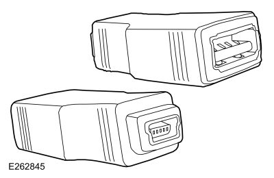 Connect a Type A 4 Pin To
Female Type Mini-B 5 Pin USB 2.0 Adaptor (Rotunda part number
CCMUSB-AF-BF5) or equivalent to the other end of the new primary front USB cable.
Connect a Type A 4 Pin To
Female Type Mini-B 5 Pin USB 2.0 Adaptor (Rotunda part number
CCMUSB-AF-BF5) or equivalent to the other end of the new primary front USB cable.
 Click here to access Guided Routine (APIM).
 Internet Explorer version 11 or greater is required to perform this Pinpoint Test.
 PINPOINT TEST Q : UNABLE TO PAIR BLUETOOTH DEVICE OR A BLUETOOTH FUNCTIONALITY IS INOPERATIVE
|
Normal Operation and Fault Conditions
REFER to: Information and Entertainment System - System Operation and Component Description (415-00 Information and Entertainment System - General Information - Vehicles With: SYNC 3, Description and Operation). Possible Sources
|
||||
| Q1 CHECK THE APIM (SYNC MODULE) BLUETOOTH PAIRING CAPABILITY | ||||
Do the Parameter Identifications (PIDs) both read "Yes"?
|
||||
| Q2 CHECK FOR CORRECT APIM (SYNC MODULE) OPERATION | ||||
Is the concern still present?
|
 Click here to access Guided Routine (APIM).
 Internet Explorer version 11 or greater is required to perform this Pinpoint Test.
 PINPOINT TEST R : THE 911 ASSIST OR EMERGENCY ASSISTANCE NOT OPERATIONAL MESSAGE DISPLAYS
|
Normal Operation and Fault Conditions
REFER to: Information and Entertainment System - System Operation and Component Description (415-00 Information and Entertainment System - General Information - Vehicles With: SYNC 3, Description and Operation). If a fault message appears indicating the 911 Assist or emergency assistance is not operational, the concern may be caused due to modules not communicating or incorrect APIM procedures. Possible Sources
|
||||
| R1 VERIFY THE 911 ASSIST OR EMERGENCY ASSISTANCE FEATURE IS ENABLED | ||||
Is the 911 Assist or emergency assistance setting enabled?
|
||||
| R2 CHECK FOR CONTINUOUS MEMORY DIAGNOSTIC TROUBLE CODES (CMDTCS) | ||||
Are any Continuous Memory Diagnostic Trouble Codes (CMDTCs) present?
|
||||
| R3 CHECK THE VEHICLE SERVICE HISTORY | ||||
Is any recent service action noted with the RCM or the APIM?
|
||||
| R4 CHECK FOR CORRECT APIM (SYNC MODULE) OPERATION | ||||
Is the concern still present?
|
 Click here to access Guided Routine (APIM).
 Internet Explorer version 11 or greater is required to perform this Pinpoint Test.
 PINPOINT TEST S : THE COMPASS/NAVIGATION IS INOPERATIVE OR DOES NOT OPERATE CORRECTLY
|
Refer to Wiring Diagrams Cell 130 for schematic and connector information. Normal Operation and Fault Conditions
REFER to: Information and Entertainment System - Component Location (415-00 Information and Entertainment System - General Information - Vehicles With: SYNC 3, Description and Operation). Audio Unit Coaxial Cable Connections 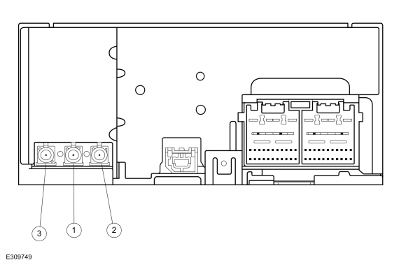
DTC Fault Trigger Conditions
Possible Sources
|
|||||||||||||||||||||
| NOTE: Prior to carrying out diagnostics, it may be beneficial to determine the cause using the Antenna Kit Tool 420-525 (Rotunda part number NUD420-525) or equivalent tool. | |||||||||||||||||||||
| S1 CHECK FOR ABS (ANTI-LOCK BRAKE SYSTEM) MODULE NETWORK COMMUNICATION | |||||||||||||||||||||
Is DTC U0121:00 present?
|
|||||||||||||||||||||
| S2 CHECK THE GPS (GLOBAL POSITIONING SYSTEM) ANTENNA RECEPTION | |||||||||||||||||||||
Are 3 or more satellites displayed for "Number of Satellites" and is "3D fix obtained" displayed for "fix Mode"?
|
|||||||||||||||||||||
| S3 CHECK COMPASS FOR CORRECT OPERATION | |||||||||||||||||||||
Does the compass operate correctly?
|
|||||||||||||||||||||
| S4 CHECK FOR CORRECT APIM (SYNC MODULE) OUTPUT VOLTAGE AT THE GPS (GLOBAL POSITIONING SYSTEM) CABLE CONNECTION | |||||||||||||||||||||
Is the voltage between 4.7 and 5.8 volts?
|
|||||||||||||||||||||
| S5 CHECK FOR PROMOTIONAL CHANNEL 1 | |||||||||||||||||||||
Does the satellite radio system receive channel 1 with normal sound quality?
|
|||||||||||||||||||||
| S6 CHECK FOR CORRECT ACM (AUDIO FRONT CONTROL MODULE) OUTPUT VOLTAGE TO THE SATELLITE RADIO ANTENNA CABLE | |||||||||||||||||||||
Is the voltage between 4.7 and 5.8 volts?
|
|||||||||||||||||||||
| S7 CHECK FOR VOLTAGE TO THE GPS (GLOBAL POSITIONING SYSTEM) /SATELLITE RADIO ANTENNA | |||||||||||||||||||||
Is the voltage between 4.7 and 5.8 volts?
|
|||||||||||||||||||||
| S8 ISOLATE THE GPS (GLOBAL POSITIONING SYSTEM) /SATELLITE RADIO ANTENNA SPLITTER CABLE | |||||||||||||||||||||
Does the compass operate correctly?
|
|||||||||||||||||||||
| S9 CHECK FOR VOLTAGE TO THE GPS (GLOBAL POSITIONING SYSTEM) ANTENNA | |||||||||||||||||||||
Is the voltage between 4.7 and 5.8 volts?
|
|||||||||||||||||||||
| S10 CHECK THE ANTENNA BASE AND MOUNTING SURFACE | |||||||||||||||||||||
Is audio unit base and mounting free of corrosion?
|
|||||||||||||||||||||
| S11 CHECK THE ROOF MOUNTED ANTENNA | |||||||||||||||||||||
Does the compass operate correctly?
|
|||||||||||||||||||||
| S12 CHECK FOR CORRECT ACM (AUDIO FRONT CONTROL MODULE) OPERATION | |||||||||||||||||||||
Is the concern still present?
|
|||||||||||||||||||||
| S13 CHECK FOR CORRECT APIM (SYNC MODULE) OPERATION | |||||||||||||||||||||
Is the concern still present?
|
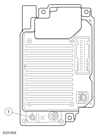 GPS cable core at the APIM
(component side)
GPS cable core at the APIM
(component side)


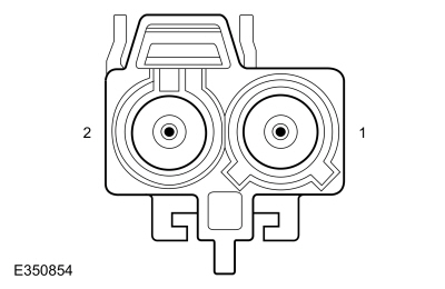 GPS/satellite radio antenna cable core at the antenna, cavity 1

 GPS antenna cable core at the antenna, cavity 1

 Click here to access Guided Routine (APIM).
 Internet Explorer version 11 or greater is required to perform this Pinpoint Test.
 PINPOINT TEST T : THE SYNC CONNECT FEATURE IS INOPERATIVE OR DOES NOT OPERATE CORRECTLY
|
Refer to Wiring Diagrams Cell 130 for schematic and connector information. Normal Operation and Fault Conditions
REFER to: Information and Entertainment System - Component Location (415-00 Information and Entertainment System - General Information - Vehicles With: SYNC 3, Description and Operation). TCU Antenna Cable Connections 
DTC Fault Trigger Conditions
Possible Sources
Visual Inspection and Pre-checks
|
||||||||||||||||||
| NOTE: This pinpoint test presumes the Diagnostic Pre-Checks have been completed. | ||||||||||||||||||
| T1 CHECK FOR CORRECT VEHICLE OPERATION | ||||||||||||||||||
Does the base function in question operate when tested on the vehicle?
|
||||||||||||||||||
| T2 VERIFY THE TCU (TELEMATIC CONTROL UNIT MODULE) PASSES THE NETWORK TEST | ||||||||||||||||||
Does the TCU pass the network test?
|
||||||||||||||||||
| T3 CHECK FOR LOST COMMUNICATION DIAGNOSTIC TROUBLE CODES (DTCS) | ||||||||||||||||||
Are any lost communication Diagnostic Trouble Codes (DTCs) set in any audio system module?
|
||||||||||||||||||
| T4 CHECK FOR PRIMARY CELLULAR ANTENNA VOLTAGE OUTPUT | ||||||||||||||||||
Is the voltage approximately 1.8 volts?
|
||||||||||||||||||
| T5 CHECK FOR VOLTAGE TO THE CELLULAR ANTENNA | ||||||||||||||||||
Is the voltage approximately 1.8 volts?
|
||||||||||||||||||
| T6 CHECK FOR CORRECT TCU (TELEMATIC CONTROL UNIT MODULE) OPERATION | ||||||||||||||||||
Is the concern still present?
|

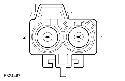 Primary cellular antenna cable core at the GPS/satellite radio antenna, cavity 2

 PINPOINT TEST U : THE VEHICLE WI-FI HOTSPOT FEATURE IS INOPERATIVE, EXPERIENCING POOR DATA SPEED OR CANNOT STREAM ANY DATA
|
Refer to Wiring Diagrams Cell 130 for schematic and connector information. Normal Operation and Fault Conditions
REFER to: Information and Entertainment System - Component Location (415-00 Information and Entertainment System - General Information - Vehicles With: SYNC 3, Description and Operation). TCU Antenna Cable Connections 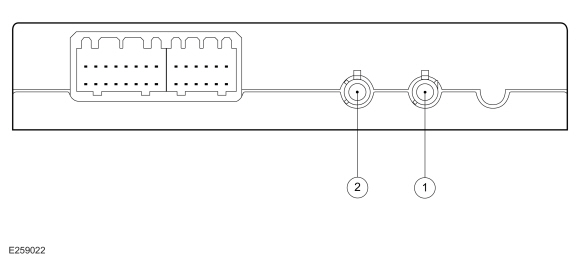
DTC Fault Trigger Conditions
Possible Sources
|
||||||||||||||||||
| U1 CHECK FOR CORRECT SYNC CONNECT OPERATION | ||||||||||||||||||
Does the SYNC Connect feature operate?
|
||||||||||||||||||
| U2 COMPARE THE WI-FI SPEED TO A SECOND DEVICE | ||||||||||||||||||
Is the data speed of the vehicle 50% or less than the second device?
|
||||||||||||||||||
| U3 CHECK FOR TCU (TELEMATIC CONTROL UNIT MODULE) SECONDARY CELLULAR ANTENNA VOLTAGE OUTPUT | ||||||||||||||||||
Is the voltage approximately 1.8 volts?
|
||||||||||||||||||
| U4 CHECK FOR VOLTAGE TO THE SECONDARY CELLULAR ANTENNA | ||||||||||||||||||
Is the voltage approximately 1.8 volts?
|
||||||||||||||||||
| U5 CHECK FOR CORRECT TCU (TELEMATIC CONTROL UNIT MODULE) OPERATION | ||||||||||||||||||
Is the concern still present?
|

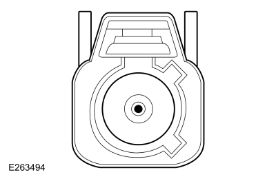 secondary cellular antenna cable core at the secondary cellular (TCU) antenna

 PINPOINT TEST V : SYNC APPLINK CONCERN
|
Normal Operation and Fault Conditions
REFER to: Information and Entertainment System - System Operation and Component Description (415-00 Information and Entertainment System - General Information - Vehicles With: SYNC 3, Description and Operation).
Possible Sources
|
| Diagnostic steps are not provided for this symptom or DTC. REFER to: Diagnostic Methods (100-00 General Information, Description and Operation). |
 PINPOINT TEST W : ANDROID AUTO™ OR APPLE CARPLAY™ CONCERN
|
Normal Operation and Fault Conditions
REFER to: Information and Entertainment System - System Operation and Component Description (415-00 Information and Entertainment System - General Information - Vehicles With: SYNC 3, Description and Operation).
Possible Sources
|
| Diagnostic steps are not provided for this symptom or DTC. REFER to: Diagnostic Methods (100-00 General Information, Description and Operation). |
 PINPOINT TEST X :
ANC (ACTIVE NOISE CONTROL)
-RELATED CONCERN
PINPOINT TEST X :
ANC (ACTIVE NOISE CONTROL)
-RELATED CONCERN|
Refer to Wiring Diagrams Cell 130 for schematic and connector information. Normal Operation and Fault Conditions
REFER to: Information and Entertainment System - System Operation and Component Description (415-00 Information and Entertainment System - General Information - Vehicles With: SYNC 3, Description and Operation). DTC Fault Trigger Conditions
Possible Sources
Visual Inspection and Pre-checks
|
|||||||||||||||||||||||||||||||
| NOTE: The ANC system is not compatible with aftermarket audio system components and architectures not approved by Ford. | |||||||||||||||||||||||||||||||
| X1 CHECK FOR ACM (AUDIO FRONT CONTROL MODULE) SPEAKER-RELATED DIAGNOSTIC TROUBLE CODES (DTCS) | |||||||||||||||||||||||||||||||
Are any ACM speaker-related Diagnostic Trouble Codes (DTCs) present?
|
|||||||||||||||||||||||||||||||
| X2 CHECK FOR DSP (AUDIO DIGITAL SIGNAL PROCESSING MODULE) SPEAKER-RELATED DIAGNOSTIC TROUBLE CODES (DTCS) | |||||||||||||||||||||||||||||||
Are any DSP speaker-related Diagnostic Trouble Codes (DTCs) present?
|
|||||||||||||||||||||||||||||||
| X3 INSPECT THE ANC (ACTIVE NOISE CONTROL) MICROPHONES | |||||||||||||||||||||||||||||||
Are the ANC microphones installed correctly?
|
|||||||||||||||||||||||||||||||
| X4 CHECK THE SUSPECT ANC (ACTIVE NOISE CONTROL) MICROPHONE INPUT CIRCUITS FOR A SHORT TO GROUND | |||||||||||||||||||||||||||||||
Are the resistances greater than 10,000 ohms?
|
|||||||||||||||||||||||||||||||
| X5 CHECK THE SUSPECT ANC (ACTIVE NOISE CONTROL) MICROPHONE INPUT CIRCUITS FOR A SHORT TO VOLTAGE | |||||||||||||||||||||||||||||||
Is any voltage present?
|
|||||||||||||||||||||||||||||||
| X6 CHECK THE SUSPECT ANC (ACTIVE NOISE CONTROL) MICROPHONE INPUT CIRCUITS FOR A SHORT TOGETHER | |||||||||||||||||||||||||||||||
Is the resistance greater than 10,000 ohms?
|
|||||||||||||||||||||||||||||||
| X7 CHECK THE SUSPECT ANC (ACTIVE NOISE CONTROL) MICROPHONE INPUT CIRCUITS FOR AN OPEN | |||||||||||||||||||||||||||||||
Are the resistances less than 3 ohms?
|
|||||||||||||||||||||||||||||||
| X8 CHECK FOR CORRECT ACM (AUDIO FRONT CONTROL MODULE) OPERATION | |||||||||||||||||||||||||||||||
Is the concern still present?
|


 PINPOINT TEST Y : U0100:00 (ACM (AUDIO FRONT CONTROL MODULE)
, DACMC (DIGITAL AUDIO CONTROL MODULE C)
, TCU (TELEMATIC CONTROL UNIT MODULE)
)
PINPOINT TEST Y : U0100:00 (ACM (AUDIO FRONT CONTROL MODULE)
, DACMC (DIGITAL AUDIO CONTROL MODULE C)
, TCU (TELEMATIC CONTROL UNIT MODULE)
)|
Normal Operation and Fault Conditions The ACM, the DACMC and the TCU communicate with the PCM over the CAN. If messages are missing or not received from the PCM module, features such as the speed compensated volume can be inoperative. DTC Fault Trigger Conditions
Possible Sources
|
||||||||||||
| Y1 VERIFY THE CONCERN | ||||||||||||
Is an observable symptom present?
|
||||||||||||
| Y2 CHECK THE NETWORK COMMUNICATION | ||||||||||||
Does the PCM pass the network test?
|
||||||||||||
| Y3 CHECK FOR NON-NETWORK DIAGNOSTIC TROUBLE CODES (DTCS) | ||||||||||||
Are any non-network Diagnostic Trouble Codes (DTCs) present?
|
||||||||||||
| Y4 CHECK FOR PCM (POWERTRAIN CONTROL MODULE) TROUBLE CODES (DTCS) | ||||||||||||
Are any non-network Diagnostic Trouble Codes (DTCs) present?
|
||||||||||||
| Y5 RECHECK FOR DTC (DIAGNOSTIC TROUBLE CODE) U0100:00 | ||||||||||||
Is DTC U0100:00 still present?
|
||||||||||||
| Y6 CHECK FOR OTHER CAUSES OF NETWORK COMMUNICATION CONCERN | ||||||||||||
|
NOTE: If new modules were installed prior to the DTC being set, the module configuration can be incorrectly set during the PMI or the PMI may not have been carried out.
Is the observable symptom still present?
|
||||||||||||
| Y7 CHECK FOR CORRECT PCM (POWERTRAIN CONTROL MODULE) OPERATION | ||||||||||||
Is the concern still present?
|
 Click here to access Guided Routine (PCM).
 Internet Explorer version 11 or greater is required to perform this Pinpoint Test.
 PINPOINT TEST Z : U0121:00 (APIM (SYNC MODULE)
)
PINPOINT TEST Z : U0121:00 (APIM (SYNC MODULE)
)|
Normal Operation and Fault Conditions The APIM communicates with the ABS module over the CAN. If messages are missing or not received from the ABS module, the GPS feature may not be accurate. DTC Fault Trigger Conditions
Possible Sources
|
||||||
| Z1 VERIFY THE CONCERN | ||||||
Is an observable symptom present?
|
||||||
| Z2 CHECK THE NETWORK COMMUNICATION | ||||||
Does the ABS module pass the network test?
|
||||||
| Z3 CHECK FOR NON-NETWORK DIAGNOSTIC TROUBLE CODES (DTCS) | ||||||
Are any non-network Diagnostic Trouble Codes (DTCs) present?
|
||||||
| Z4 CHECK FOR NON-NETWORK ABS (ANTI-LOCK BRAKE SYSTEM) MODULE DIAGNOSTIC TROUBLE CODES (DTCS) | ||||||
Are any non-network Diagnostic Trouble Codes (DTCs) present?
|
||||||
| Z5 RECHECK FOR DTC (DIAGNOSTIC TROUBLE CODE) U0121:00 | ||||||
Is DTC U0121:00 still present?
|
||||||
| Z6 CHECK FOR OTHER CAUSES OF NETWORK COMMUNICATION CONCERN | ||||||
|
NOTE: If new modules were installed prior to the DTC being set, the module configuration can be incorrectly set during the PMI or the PMI may not have been carried out.
Is the observable symptom still present?
|
||||||
| Z7 CHECK FOR CORRECT ABS (ANTI-LOCK BRAKE SYSTEM) MODULE OPERATION | ||||||
Is the concern still present?
|
 PINPOINT TEST AA : U0140:00 (ACM (AUDIO FRONT CONTROL MODULE)
, APIM (SYNC MODULE)
, DACMC (DIGITAL AUDIO CONTROL MODULE C)
, DSP (AUDIO DIGITAL SIGNAL PROCESSING MODULE)
, FCIM (FRONT CONTROLS INTERFACE MODULE)
, TCU (TELEMATIC CONTROL UNIT MODULE)
)
PINPOINT TEST AA : U0140:00 (ACM (AUDIO FRONT CONTROL MODULE)
, APIM (SYNC MODULE)
, DACMC (DIGITAL AUDIO CONTROL MODULE C)
, DSP (AUDIO DIGITAL SIGNAL PROCESSING MODULE)
, FCIM (FRONT CONTROLS INTERFACE MODULE)
, TCU (TELEMATIC CONTROL UNIT MODULE)
)|
Normal Operation and Fault Conditions The ACM, the APIM, the DACMC, the DSP, the FCIM and the TCU communicate with the BCM over the CAN. If messages are missing or not received from the BCM, the display screen brightness may not operate not operate correctly. DTC Fault Trigger Conditions
Possible Sources
|
|||||||||||||||||||||
| AA1 VERIFY THE CONCERN | |||||||||||||||||||||
Is an observable symptom present?
|
|||||||||||||||||||||
| AA2 CHECK THE NETWORK COMMUNICATION | |||||||||||||||||||||
Does the BCM pass the network test?
|
|||||||||||||||||||||
| AA3 CHECK FOR NON-NETWORK DIAGNOSTIC TROUBLE CODES (DTCS) | |||||||||||||||||||||
Are any non-network Diagnostic Trouble Codes (DTCs) present?
|
|||||||||||||||||||||
| AA4 CHECK FOR NON-NETWORK BCM (BODY CONTROL MODULE) DIAGNOSTIC TROUBLE CODES (DTCS) | |||||||||||||||||||||
Are any non-network Diagnostic Trouble Codes (DTCs) present?
|
|||||||||||||||||||||
| AA5 RECHECK FOR DTC (DIAGNOSTIC TROUBLE CODE) U0140:00 | |||||||||||||||||||||
Is DTC U0140:00 still present?
|
|||||||||||||||||||||
| AA6 CHECK FOR OTHER CAUSES OF NETWORK COMMUNICATION CONCERN | |||||||||||||||||||||
|
NOTE: If new modules were installed prior to the DTC being set, the module configuration can be incorrectly set during the PMI or the PMI may not have been carried out.
Is the observable symptom still present?
|
|||||||||||||||||||||
| AA7 CHECK FOR CORRECT BCM (BODY CONTROL MODULE) OPERATION | |||||||||||||||||||||
Is the concern still present?
|
 PINPOINT TEST AB : U0151:00 (APIM (SYNC MODULE)
)
PINPOINT TEST AB : U0151:00 (APIM (SYNC MODULE)
)|
Normal Operation and Fault Conditions The APIM communicates with the RCM over the CAN. If messages are missing or not received from the RCM, features such as the 911 Assist or Emergency Assist or the passenger airbag disable indicator may be inoperative. DTC Fault Trigger Conditions
Possible Sources
|
||||||
| AB1 VERIFY THE CONCERN | ||||||
Is an observable symptom present?
|
||||||
| AB2 CHECK THE NETWORK COMMUNICATION | ||||||
Does the RCM pass the network test?
|
||||||
| AB3 CHECK FOR NON-NETWORK DIAGNOSTIC TROUBLE CODES (DTCS) | ||||||
Are any non-network Diagnostic Trouble Codes (DTCs) present?
|
||||||
| AB4 CHECK FOR NON-NETWORK RCM (RESTRAINTS CONTROL MODULE) DIAGNOSTIC TROUBLE CODES (DTCS) | ||||||
Are any non-network Diagnostic Trouble Codes (DTCs) present?
|
||||||
| AB5 RECHECK FOR DTC (DIAGNOSTIC TROUBLE CODE) U0151:00 | ||||||
Is DTC U0151:00 still present?
|
||||||
| AB6 CHECK FOR OTHER CAUSES OF NETWORK COMMUNICATION CONCERN | ||||||
|
NOTE: If new modules were installed prior to the DTC being set, the module configuration can be incorrectly set during the PMI or the PMI may not have been carried out.
Is the observable symptom still present?
|
||||||
| AB7 CHECK FOR CORRECT RCM (RESTRAINTS CONTROL MODULE) OPERATION | ||||||
Is the concern still present?
|
 PINPOINT TEST AC : U0155:00 (ACM (AUDIO FRONT CONTROL MODULE)
, APIM (SYNC MODULE)
, DSP (AUDIO DIGITAL SIGNAL PROCESSING MODULE)
, FCIM (FRONT CONTROLS INTERFACE MODULE)
)
PINPOINT TEST AC : U0155:00 (ACM (AUDIO FRONT CONTROL MODULE)
, APIM (SYNC MODULE)
, DSP (AUDIO DIGITAL SIGNAL PROCESSING MODULE)
, FCIM (FRONT CONTROLS INTERFACE MODULE)
)|
Normal Operation and Fault Conditions The ACM, the APIM, the DSP and the FCIM communicate with the IPC over the CAN . If messages are missing or not received from the IPC, features such as the display illumination or warning chimes may not operate correctly. DTC Fault Trigger Conditions
Possible Sources
|
|||||||||||||||
| AC1 VERIFY THE CONCERN | |||||||||||||||
Is an observable symptom present?
|
|||||||||||||||
| AC2 CHECK THE NETWORK COMMUNICATION | |||||||||||||||
Does the IPC pass the network test?
|
|||||||||||||||
| AC3 CHECK FOR NON-NETWORK DIAGNOSTIC TROUBLE CODES (DTCS) | |||||||||||||||
Are any non-network Diagnostic Trouble Codes (DTCs) present?
|
|||||||||||||||
| AC4 CHECK FOR NON-NETWORK IPC (INSTRUMENT PANEL CLUSTER) DIAGNOSTIC TROUBLE CODES (DTCS) | |||||||||||||||
Are any non-network Diagnostic Trouble Codes (DTCs) present?
|
|||||||||||||||
| AC5 RECHECK FOR DTC (DIAGNOSTIC TROUBLE CODE) U0155:00 | |||||||||||||||
Is DTC U0155:00 still present?
|
|||||||||||||||
| AC6 CHECK FOR OTHER CAUSES OF NETWORK COMMUNICATION CONCERN | |||||||||||||||
|
NOTE: If new modules were installed prior to the DTC being set, the module configuration can be incorrectly set during the PMI or the PMI may not have been carried out.
Is the observable symptom still present?
|
|||||||||||||||
| AC7 CHECK FOR CORRECT IPC (INSTRUMENT PANEL CLUSTER) OPERATION | |||||||||||||||
Is the concern still present?
|
 PINPOINT TEST AD : U0159:00 (APIM (SYNC MODULE)
)
PINPOINT TEST AD : U0159:00 (APIM (SYNC MODULE)
)|
Normal Operation and Fault Conditions The APIM communicates with the PAM over the CAN. If messages are missing or not received from the PAM, features such as the parking aid may not operate correctly. DTC Fault Trigger Conditions
Possible Sources
|
||||||
| AD1 VERIFY THE CONCERN | ||||||
Is an observable symptom present?
|
||||||
| AD2 CHECK THE NETWORK COMMUNICATION | ||||||
Does the PAM pass the network test?
|
||||||
| AD3 CHECK FOR NON-NETWORK DIAGNOSTIC TROUBLE CODES (DTCS) | ||||||
Are any non-network Diagnostic Trouble Codes (DTCs) present?
|
||||||
| AD4 CHECK FOR NON-NETWORK PAM (PARKING ASSIST CONTROL MODULE) DIAGNOSTIC TROUBLE CODES (DTCS) | ||||||
Are any non-network Diagnostic Trouble Codes (DTCs) present?
|
||||||
| AD5 RECHECK FOR DTC (DIAGNOSTIC TROUBLE CODE) U0159:00 | ||||||
Is DTC U0159:00 still present?
|
||||||
| AD6 CHECK FOR OTHER CAUSES OF NETWORK COMMUNICATION CONCERN | ||||||
|
NOTE: If new modules were installed prior to the DTC being set, the module configuration can be incorrectly set during the PMI or the PMI may not have been carried out.
Is the observable symptom still present?
|
||||||
| AD7 CHECK FOR CORRECT PAM (PARKING ASSIST CONTROL MODULE) OPERATION | ||||||
Is the concern still present?
|
 PINPOINT TEST AE : U0184:00 (APIM (SYNC MODULE)
, DSP (AUDIO DIGITAL SIGNAL PROCESSING MODULE)
)
PINPOINT TEST AE : U0184:00 (APIM (SYNC MODULE)
, DSP (AUDIO DIGITAL SIGNAL PROCESSING MODULE)
)|
Normal Operation and Fault Conditions The APIM and the DSP communicate with the ACM over the CAN. If messages are missing or not received from the ACM, the touchscreen display is blank. DTC Fault Trigger Conditions
Possible Sources
|
|||||||||
| AE1 VERIFY THE CONCERN | |||||||||
Is an observable symptom present?
|
|||||||||
| AE2 CHECK THE NETWORK COMMUNICATION | |||||||||
Does the ACM pass the network test?
|
|||||||||
| AE3 CHECK FOR NON-NETWORK DIAGNOSTIC TROUBLE CODES (DTCS) | |||||||||
Are any non-network Diagnostic Trouble Codes (DTCs) present?
|
|||||||||
| AE4 CHECK FOR NON-NETWORK ACM (AUDIO FRONT CONTROL MODULE) DIAGNOSTIC TROUBLE CODES (DTCS) | |||||||||
Are any non-network Diagnostic Trouble Codes (DTCs) present?
|
|||||||||
| AE5 RECHECK FOR DTC (DIAGNOSTIC TROUBLE CODE) U0184:00 | |||||||||
Is DTC U0184:00 still present?
|
|||||||||
| AE6 CHECK FOR OTHER CAUSES OF NETWORK COMMUNICATION CONCERN | |||||||||
|
NOTE: If new modules were installed prior to the DTC being set, the module configuration can be incorrectly set during the PMI or the PMI may not have been carried out.
Is the observable symptom still present?
|
|||||||||
| AE7 CHECK FOR CORRECT ACM (AUDIO FRONT CONTROL MODULE) OPERATION | |||||||||
Is the concern still present?
|
 PINPOINT TEST AF : U0198:00 (APIM (SYNC MODULE)
)
PINPOINT TEST AF : U0198:00 (APIM (SYNC MODULE)
)|
Normal Operation and Fault Conditions The APIM communicates with the TCU over the CAN. If messages are missing or not received from the TCU, the SYNC Connect feature may not operate correctly. DTC Fault Trigger Conditions
Possible Sources
|
||||||
| AF1 VERIFY THE CONCERN | ||||||
Is an observable symptom present?
|
||||||
| AF2 CHECK THE NETWORK COMMUNICATION | ||||||
Does the TCU pass the network test?
|
||||||
| AF3 CHECK FOR NON-NETWORK DIAGNOSTIC TROUBLE CODES (DTCS) | ||||||
Are any non-network Diagnostic Trouble Codes (DTCs) present?
|
||||||
| AF4 CHECK FOR NON-NETWORK TCU (TELEMATIC CONTROL UNIT MODULE) DIAGNOSTIC TROUBLE CODES (DTCS) | ||||||
Are any non-network Diagnostic Trouble Codes (DTCs) present?
|
||||||
| AF5 RECHECK FOR DTC (DIAGNOSTIC TROUBLE CODE) U0198:00 | ||||||
Is DTC U0198:00 still present?
|
||||||
| AF6 CHECK FOR OTHER CAUSES OF NETWORK COMMUNICATION CONCERN | ||||||
|
NOTE: If new modules were installed prior to the DTC being set, the module configuration can be incorrectly set during the PMI or the PMI may not have been carried out.
Is the observable symptom still present?
|
||||||
| AF7 CHECK FOR CORRECT TCU (TELEMATIC CONTROL UNIT MODULE) OPERATION | ||||||
Is the concern still present?
|
 PINPOINT TEST AG : U0208:00 (APIM (SYNC MODULE)
)
PINPOINT TEST AG : U0208:00 (APIM (SYNC MODULE)
)|
Normal Operation and Fault Conditions The APIM communicates with the SCME over the CAN. If messages are missing or not received from the SCME, the climate controlled seat may not operate correctly. DTC Fault Trigger Conditions
Possible Sources
|
||||||
| AG1 VERIFY THE CONCERN | ||||||
Is an observable symptom present?
|
||||||
| AG2 CHECK THE NETWORK COMMUNICATION | ||||||
Does the SCME pass the network test?
|
||||||
| AG3 CHECK FOR NON-NETWORK DIAGNOSTIC TROUBLE CODES (DTCS) | ||||||
Are any non-network Diagnostic Trouble Codes (DTCs) present?
|
||||||
| AG4 CHECK FOR NON-NETWORK SCME (FRONT SEAT CLIMATE CONTROL MODULE) DIAGNOSTIC TROUBLE CODES (DTCS) | ||||||
Are any non-network Diagnostic Trouble Codes (DTCs) present?
|
||||||
| AG5 RECHECK FOR DTC (DIAGNOSTIC TROUBLE CODE) U0208:00 | ||||||
Is DTC U0208:00 still present?
|
||||||
| AG6 CHECK FOR OTHER CAUSES OF NETWORK COMMUNICATION CONCERN | ||||||
|
NOTE: If new modules were installed prior to the DTC being set, the module configuration can be incorrectly set during the PMI or the PMI may not have been carried out.
Is the observable symptom still present?
|
||||||
| AG7 CHECK FOR CORRECT SCME (FRONT SEAT CLIMATE CONTROL MODULE) OPERATION | ||||||
Is the concern still present?
|
 PINPOINT TEST AH : U0232:00 (APIM (SYNC MODULE)
)
PINPOINT TEST AH : U0232:00 (APIM (SYNC MODULE)
)|
Normal Operation and Fault Conditions The APIM communicates with the SODL over the CAN. If messages are missing or not received from the SODL, features such as the side detection settings or warning chimes may not operate correctly. DTC Fault Trigger Conditions
Possible Sources
|
||||||
| AH1 VERIFY THE CONCERN | ||||||
Is an observable symptom present?
|
||||||
| AH2 CHECK THE NETWORK COMMUNICATION | ||||||
Does the SODL pass the network test?
|
||||||
| AH3 CHECK FOR NON-NETWORK DIAGNOSTIC TROUBLE CODES (DTCS) | ||||||
Are any non-network Diagnostic Trouble Codes (DTCs) present?
|
||||||
| AH4 CHECK FOR NON-NETWORK SODL (SIDE OBSTACLE DETECTION CONTROL MODULE LH) DIAGNOSTIC TROUBLE CODES (DTCS) | ||||||
Are any non-network Diagnostic Trouble Codes (DTCs) present?
|
||||||
| AH5 RECHECK FOR DTC (DIAGNOSTIC TROUBLE CODE) U0232:00 | ||||||
Is DTC U0232:00 still present?
|
||||||
| AH6 CHECK FOR OTHER CAUSES OF NETWORK COMMUNICATION CONCERN | ||||||
|
NOTE: If new modules were installed prior to the DTC being set, the module configuration can be incorrectly set during the PMI or the PMI may not have been carried out.
Is the observable symptom still present?
|
||||||
| AH7 CHECK FOR CORRECT SODL (SIDE OBSTACLE DETECTION CONTROL MODULE LH) OPERATION | ||||||
Is the concern still present?
|
 PINPOINT TEST AI : U0233:00 (APIM (SYNC MODULE)
)
PINPOINT TEST AI : U0233:00 (APIM (SYNC MODULE)
)|
Normal Operation and Fault Conditions The APIM communicates with the SODR over the CAN. If messages are missing or not received from the SODR, features such as the side detection settings or warning chimes may not operate correctly. DTC Fault Trigger Conditions
Possible Sources
|
||||||
| AI1 VERIFY THE CONCERN | ||||||
Is an observable symptom present?
|
||||||
| AI2 CHECK THE NETWORK COMMUNICATION | ||||||
Does the SODR pass the network test?
|
||||||
| AI3 CHECK FOR NON-NETWORK DIAGNOSTIC TROUBLE CODES (DTCS) | ||||||
Are any non-network Diagnostic Trouble Codes (DTCs) present?
|
||||||
| AI4 CHECK FOR NON-NETWORK SODR (SIDE OBSTACLE DETECTION CONTROL MODULE RH) DIAGNOSTIC TROUBLE CODES (DTCS) | ||||||
Are any non-network Diagnostic Trouble Codes (DTCs) present?
|
||||||
| AI5 RECHECK FOR DTC (DIAGNOSTIC TROUBLE CODE) U0233:00 | ||||||
Is DTC U0233:00 still present?
|
||||||
| AI6 CHECK FOR OTHER CAUSES OF NETWORK COMMUNICATION CONCERN | ||||||
|
NOTE: If new modules were installed prior to the DTC being set, the module configuration can be incorrectly set during the PMI or the PMI may not have been carried out.
Is the observable symptom still present?
|
||||||
| AI7 CHECK FOR CORRECT SODR (SIDE OBSTACLE DETECTION CONTROL MODULE RH) OPERATION | ||||||
Is the concern still present?
|
 PINPOINT TEST AJ : U0237:00 (ACM (AUDIO FRONT CONTROL MODULE)
, DSP (AUDIO DIGITAL SIGNAL PROCESSING MODULE)
)
PINPOINT TEST AJ : U0237:00 (ACM (AUDIO FRONT CONTROL MODULE)
, DSP (AUDIO DIGITAL SIGNAL PROCESSING MODULE)
)|
Normal Operation and Fault Conditions The ACM and the DSP communicate with the DACMC over the CAN. If messages are missing or not received from the DACMC, features such as the ANC may not operate correctly. DTC Fault Trigger Conditions
Possible Sources
|
|||||||||
| AJ1 VERIFY THE CONCERN | |||||||||
Is an observable symptom present?
|
|||||||||
| AJ2 CHECK THE NETWORK COMMUNICATION | |||||||||
Does the DACMC pass the network test?
|
|||||||||
| AJ3 CHECK FOR NON-NETWORK DIAGNOSTIC TROUBLE CODES (DTCS) | |||||||||
Are any non-network Diagnostic Trouble Codes (DTCs) present?
|
|||||||||
| AJ4 CHECK FOR NON-NETWORK DACMC (DIGITAL AUDIO CONTROL MODULE C) DIAGNOSTIC TROUBLE CODES (DTCS) | |||||||||
Are any non-network Diagnostic Trouble Codes (DTCs) present?
|
|||||||||
| AJ5 RECHECK FOR DTC (DIAGNOSTIC TROUBLE CODE) U0238:00 | |||||||||
Is DTC U0238:00 still present?
|
|||||||||
| AJ6 CHECK FOR OTHER CAUSES OF NETWORK COMMUNICATION CONCERN | |||||||||
|
NOTE: If new modules were installed prior to the DTC being set, the module configuration can be incorrectly set during the PMI or the PMI may not have been carried out.
Is the observable symptom still present?
|
|||||||||
| AJ7 CHECK FOR CORRECT DACMC (DIGITAL AUDIO CONTROL MODULE C) OPERATION | |||||||||
Is the concern still present?
|
 PINPOINT TEST AK : U0238:00 (ACM (AUDIO FRONT CONTROL MODULE)
, APIM (SYNC MODULE)
)
PINPOINT TEST AK : U0238:00 (ACM (AUDIO FRONT CONTROL MODULE)
, APIM (SYNC MODULE)
)|
Normal Operation and Fault Conditions The ACM and the APIM communicate with the audio DSP module over the CAN. If messages are missing or not received from the DSP, features such as the ANC may not operate correctly. DTC Fault Trigger Conditions
Possible Sources
|
|||||||||
| AK1 VERIFY THE CONCERN | |||||||||
Is an observable symptom present?
|
|||||||||
| AK2 CHECK THE NETWORK COMMUNICATION | |||||||||
Does the DSP pass the network test?
|
|||||||||
| AK3 CHECK FOR NON-NETWORK DIAGNOSTIC TROUBLE CODES (DTCS) | |||||||||
Are any non-network Diagnostic Trouble Codes (DTCs) present?
|
|||||||||
| AK4 CHECK FOR NON-NETWORK DSP (AUDIO DIGITAL SIGNAL PROCESSING MODULE) DIAGNOSTIC TROUBLE CODES (DTCS) | |||||||||
Are any non-network Diagnostic Trouble Codes (DTCs) present?
|
|||||||||
| AK5 RECHECK FOR DTC (DIAGNOSTIC TROUBLE CODE) U0238:00 | |||||||||
Is DTC U0238:00 still present?
|
|||||||||
| AK6 CHECK FOR OTHER CAUSES OF NETWORK COMMUNICATION CONCERN | |||||||||
|
NOTE: If new modules were installed prior to the DTC being set, the module configuration can be incorrectly set during the PMI or the PMI may not have been carried out.
Is the observable symptom still present?
|
|||||||||
| AK7 CHECK FOR CORRECT DSP (AUDIO DIGITAL SIGNAL PROCESSING MODULE) OPERATION | |||||||||
Is the concern still present?
|
 PINPOINT TEST AL : U0253:00 (ACM (AUDIO FRONT CONTROL MODULE)
, DSP (AUDIO DIGITAL SIGNAL PROCESSING MODULE)
, FCIM (FRONT CONTROLS INTERFACE MODULE)
, TCU (TELEMATIC CONTROL UNIT MODULE)
)
PINPOINT TEST AL : U0253:00 (ACM (AUDIO FRONT CONTROL MODULE)
, DSP (AUDIO DIGITAL SIGNAL PROCESSING MODULE)
, FCIM (FRONT CONTROLS INTERFACE MODULE)
, TCU (TELEMATIC CONTROL UNIT MODULE)
)|
Normal Operation and Fault Conditions The ACM, the DSP, the FCIM and the TCU communicate with the APIM over the CAN. If messages are missing or not received from the APIM, the display is blank. DTC Fault Trigger Conditions
Possible Sources
|
|||||||||||||||
| AL1 VERIFY THE CONCERN | |||||||||||||||
Is an observable symptom present?
|
|||||||||||||||
| AL2 CHECK THE NETWORK COMMUNICATION | |||||||||||||||
Does the APIM pass the network test?
|
|||||||||||||||
| AL3 CHECK FOR NON-NETWORK DIAGNOSTIC TROUBLE CODES (DTCS) | |||||||||||||||
Are any non-network Diagnostic Trouble Codes (DTCs) present?
|
|||||||||||||||
| AL4 CHECK FOR NON-NETWORK APIM (SYNC MODULE) DIAGNOSTIC TROUBLE CODES (DTCS) | |||||||||||||||
Are any non-network Diagnostic Trouble Codes (DTCs) present?
|
|||||||||||||||
| AL5 RECHECK FOR DTC (DIAGNOSTIC TROUBLE CODE) U0253:00 | |||||||||||||||
Is DTC U0253:00 still present?
|
|||||||||||||||
| AL6 CHECK FOR OTHER CAUSES OF NETWORK COMMUNICATION CONCERN | |||||||||||||||
|
NOTE: If new modules were installed prior to the DTC being set, the module configuration can be incorrectly set during the PMI or the PMI may not have been carried out.
Is the observable symptom still present?
|
|||||||||||||||
| AL7 CHECK FOR CORRECT APIM (SYNC MODULE) OPERATION | |||||||||||||||
Is the concern still present?
|
 Click here to access Guided Routine (APIM).
 Internet Explorer version 11 or greater is required to perform this Pinpoint Test.
 PINPOINT TEST AM : U0256:00 (ACM (AUDIO FRONT CONTROL MODULE)
, APIM (SYNC MODULE)
, DSP (AUDIO DIGITAL SIGNAL PROCESSING MODULE)
)
PINPOINT TEST AM : U0256:00 (ACM (AUDIO FRONT CONTROL MODULE)
, APIM (SYNC MODULE)
, DSP (AUDIO DIGITAL SIGNAL PROCESSING MODULE)
)|
Normal Operation and Fault Conditions The ACM, the APIM and the DSP communicate with the FCIM over the CAN. If messages are missing or not received from the FCIM, button presses on the FCIM may not operate correctly. DTC Fault Trigger Conditions
Possible Sources
|
||||||||||||
| AM1 VERIFY THE CONCERN | ||||||||||||
Is an observable symptom present?
|
||||||||||||
| AM2 CHECK THE NETWORK COMMUNICATION | ||||||||||||
Does the FCIM pass the network test?
|
||||||||||||
| AM3 CHECK FOR NON-NETWORK DIAGNOSTIC TROUBLE CODES (DTCS) | ||||||||||||
Are any non-network Diagnostic Trouble Codes (DTCs) present?
|
||||||||||||
| AM4 CHECK FOR NON-NETWORK FCIM (FRONT CONTROLS INTERFACE MODULE) DIAGNOSTIC TROUBLE CODES (DTCS) | ||||||||||||
Are any non-network Diagnostic Trouble Codes (DTCs) present?
|
||||||||||||
| AM5 RECHECK FOR DTC (DIAGNOSTIC TROUBLE CODE) U0256:00 | ||||||||||||
Is DTC U0256:00 still present?
|
||||||||||||
| AM6 CHECK FOR OTHER CAUSES OF NETWORK COMMUNICATION CONCERN | ||||||||||||
|
NOTE: If new modules were installed prior to the DTC being set, the module configuration can be incorrectly set during the PMI or the PMI may not have been carried out.
Is the observable symptom still present?
|
||||||||||||
| AM7 CHECK FOR CORRECT FCIM (FRONT CONTROLS INTERFACE MODULE) OPERATION | ||||||||||||
Is the concern still present?
|
 PINPOINT TEST AN : U3003:16 (ACM (AUDIO FRONT CONTROL MODULE)
, APIM (SYNC MODULE)
, DACMC (DIGITAL AUDIO CONTROL MODULE C)
, DSP (AUDIO DIGITAL SIGNAL PROCESSING MODULE)
, FCIM (FRONT CONTROLS INTERFACE MODULE)
, TCU (TELEMATIC CONTROL UNIT MODULE)
)
PINPOINT TEST AN : U3003:16 (ACM (AUDIO FRONT CONTROL MODULE)
, APIM (SYNC MODULE)
, DACMC (DIGITAL AUDIO CONTROL MODULE C)
, DSP (AUDIO DIGITAL SIGNAL PROCESSING MODULE)
, FCIM (FRONT CONTROLS INTERFACE MODULE)
, TCU (TELEMATIC CONTROL UNIT MODULE)
)|
Refer to Wiring Diagrams Cell 130 for schematic and connector information. Normal Operation and Fault Conditions The modules monitor the supplied voltage and set a DTC if it falls below a threshold. DTC Fault Trigger Conditions
Possible Sources
|
||||||||||||||||||||||||||||||||||||||||
| AN1 RECHECK FOR LOW VOLTAGE DIAGNOSTIC TROUBLE CODES (DTCS) | ||||||||||||||||||||||||||||||||||||||||
Is DTC U3003:16 still present?
|
||||||||||||||||||||||||||||||||||||||||
| AN2 CHECK FOR CHARGING SYSTEM DIAGNOSTIC TROUBLE CODES (DTCS) | ||||||||||||||||||||||||||||||||||||||||
Are any voltage-related Diagnostic Trouble Codes (DTCs) present?
|
||||||||||||||||||||||||||||||||||||||||
| AN3 CHECK THE BATTERY CONDITION AND STATE OF CHARGE | ||||||||||||||||||||||||||||||||||||||||
Is the battery OK and fully charged?
|
||||||||||||||||||||||||||||||||||||||||
| AN4 COMPARE THE SUSPECT MODULE VOLTAGE SUPPLY PID (PARAMETER IDENTIFICATION) TO THE BATTERY VOLTAGE | ||||||||||||||||||||||||||||||||||||||||
Is the voltage reading within 0.2 volt of the recorded battery voltage?
|
||||||||||||||||||||||||||||||||||||||||
| AN5 CHECK THE MODULE VOLTAGE SUPPLY CIRCUIT FOR HIGH RESISTANCE | ||||||||||||||||||||||||||||||||||||||||
Is the voltage reading within 0.2 volt of the recorded battery voltage?
|
||||||||||||||||||||||||||||||||||||||||
| AN6 CHECK THE SUSPECT MODULE GROUND CIRCUIT FOR HIGH RESISTANCE | ||||||||||||||||||||||||||||||||||||||||
Is the voltage reading within 0.2 volt of the recorded battery voltage?
|
||||||||||||||||||||||||||||||||||||||||
| AN7 CHECK FOR CORRECT ACM (AUDIO FRONT CONTROL MODULE) / DACMC (DIGITAL AUDIO CONTROL MODULE C) OPERATION | ||||||||||||||||||||||||||||||||||||||||
Is the concern still present?
|
||||||||||||||||||||||||||||||||||||||||
| AN8 CHECK FOR CORRECT APIM (SYNC MODULE) OPERATION | ||||||||||||||||||||||||||||||||||||||||
Is the concern still present?
|
||||||||||||||||||||||||||||||||||||||||
| AN9 CHECK FOR CORRECT DSP (AUDIO DIGITAL SIGNAL PROCESSING MODULE) OPERATION | ||||||||||||||||||||||||||||||||||||||||
Is the concern still present?
|
||||||||||||||||||||||||||||||||||||||||
| AN10 CHECK FOR CORRECT FCIM (FRONT CONTROLS INTERFACE MODULE) OPERATION | ||||||||||||||||||||||||||||||||||||||||
Is the concern still present?
|
||||||||||||||||||||||||||||||||||||||||
| AN11 CHECK FOR CORRECT TCU (TELEMATIC CONTROL UNIT MODULE) OPERATION | ||||||||||||||||||||||||||||||||||||||||
Is the concern still present?
|


 Click here to access Guided Routine (APIM).
 Internet Explorer version 11 or greater is required to perform this Pinpoint Test.
 PINPOINT TEST AO : U3003:17 (ACM (AUDIO FRONT CONTROL MODULE)
, APIM (SYNC MODULE)
, DACMC (DIGITAL AUDIO CONTROL MODULE C)
, DSP (AUDIO DIGITAL SIGNAL PROCESSING MODULE)
, FCIM (FRONT CONTROLS INTERFACE MODULE)
, TCU (TELEMATIC CONTROL UNIT MODULE)
)
PINPOINT TEST AO : U3003:17 (ACM (AUDIO FRONT CONTROL MODULE)
, APIM (SYNC MODULE)
, DACMC (DIGITAL AUDIO CONTROL MODULE C)
, DSP (AUDIO DIGITAL SIGNAL PROCESSING MODULE)
, FCIM (FRONT CONTROLS INTERFACE MODULE)
, TCU (TELEMATIC CONTROL UNIT MODULE)
)|
Normal Operation and Fault Conditions The modules monitor the supplied voltage and set a DTC if it rises above a threshold. DTC Fault Trigger Conditions
Possible Sources
|
|||||||||||||||||||||
| NOTE: DTC U3003:17 may be stored in the module memory due to past battery charging or vehicle jump starting events. | |||||||||||||||||||||
| AO1 CHECK FOR HIGH VOLTAGE DIAGNOSTIC TROUBLE CODES (DTCS) SET IN OTHER MODULES | |||||||||||||||||||||
Are any charging or over-voltage related voltage Diagnostic Trouble Codes (DTCs) present in multiple modules?
|
|||||||||||||||||||||
| AO2 CHECK THE BATTERY VOLTAGE WITH THE ENGINE RUNNING | |||||||||||||||||||||
Does the battery voltage rise to 15.5 volts or higher?
|
|||||||||||||||||||||
| AO3 RECHECK FOR THE HIGH VOLTAGE DTC (DIAGNOSTIC TROUBLE CODE) | |||||||||||||||||||||
Is DTC U3003:17 still present?
|
|||||||||||||||||||||
| AO4 CHECK FOR CORRECT ACM (AUDIO FRONT CONTROL MODULE) / DACMC (DIGITAL AUDIO CONTROL MODULE C) OPERATION | |||||||||||||||||||||
Is the concern still present?
|
|||||||||||||||||||||
| AO5 CHECK FOR CORRECT APIM (SYNC MODULE) OPERATION | |||||||||||||||||||||
Is the concern still present?
|
|||||||||||||||||||||
| AO6 CHECK FOR CORRECT DSP (AUDIO DIGITAL SIGNAL PROCESSING MODULE) OPERATION | |||||||||||||||||||||
Is the concern still present?
|
|||||||||||||||||||||
| AO7 CHECK FOR CORRECT FCIM (FRONT CONTROLS INTERFACE MODULE) OPERATION | |||||||||||||||||||||
Is the concern still present?
|
|||||||||||||||||||||
| AO8 CHECK FOR CORRECT TCU (TELEMATIC CONTROL UNIT MODULE) OPERATION | |||||||||||||||||||||
Is the concern still present?
|
 Click here to access Guided Routine (APIM).
 Internet Explorer version 11 or greater is required to perform this Pinpoint Test.
 PINPOINT TEST AP : SOLID STATE DRIVER PROTECTION CONCERN
|
Normal Operation and Fault Conditions The FCIM temporarily disables a HVAC control output when an excessive current draw exists (such as a short to ground). The FCIM cannot enable the output until the cause of the short is corrected. DTC Fault Trigger Conditions
Possible Sources
|
||||||
| AP1 DIAGNOSE ALL OTHER DIAGNOSTIC TROUBLE CODES (DTCS) PRESENT | ||||||
Is the Solid State Protection DTC still present?
|
 PINPOINT TEST AQ : BUS OFF
|
Refer to Wiring Diagrams Cell 14 for schematic and connector information. DTC Fault Trigger Conditions
Possible Sources
|
||||||
| AQ1 DIAGNOSE THE INTERMITTENT FAULT | ||||||
|
NOTE: The module was unable to communicate on the network at a point in time. The fault is not currently present since the module had to communicate with the diagnostic scan tool to report this DTC.
Is the DTC still present?
|
 PINPOINT TEST AR : INVALID DATA RECEIVED
|
DTC Fault Trigger Conditions
Possible Sources
|
||||||||||||||||||||||||||||||||||||||||||
| AR1 CHECK FOR DIAGNOSTIC TROUBLE CODES (DTCS) FROM THE MODULE SENDING INVALID DATA | ||||||||||||||||||||||||||||||||||||||||||
Are any Diagnostic Trouble Codes (DTCs) present from the module sending the invalid data?
|
 PINPOINT TEST AS : MODULE CONFIGURATION FAULT
|
DTC Fault Trigger Conditions
Possible Sources
|
||||||||||||||||||||||||||||||||||||||||||||||||||||||||||||||||||||||||||||||
| AS1 CARRY OUT THE PMI (PROGRAMMABLE MODULE INSTALLATION) FOR THE SUSPECT MODULE | ||||||||||||||||||||||||||||||||||||||||||||||||||||||||||||||||||||||||||||||
Is the original DTC still present?
|
 Click here to access Guided Routine (APIM).
 Internet Explorer version 11 or greater is required to perform this Pinpoint Test.
For all other modules, INSTALL a new module in
question. REFER to the appropriate module Removal and Installation
procedure in this section.
Internet Explorer version 11 or greater is required to perform this Pinpoint Test.
For all other modules, INSTALL a new module in
question. REFER to the appropriate module Removal and Installation
procedure in this section.
 PINPOINT TEST AT : INTERNAL MODULE FAILURE
|
DTC Fault Trigger Conditions
Possible Sources
|
||||||||||||||||||||||||||||||||||||||||||||||||||||||||||||
| AT1 INSTALL A NEW SUSPECT MODULE | ||||||||||||||||||||||||||||||||||||||||||||||||||||||||||||
Is the concern still present?
|
 Click here to access Guided Routine (APIM).
 Internet Explorer version 11 or greater is required to perform this Pinpoint Test.
 PINPOINT TEST AU :
TCU (TELEMATIC CONTROL UNIT MODULE)
DTC (DIAGNOSTIC TROUBLE CODE)
U3000:04, U3000:09 OR U3000:52
PINPOINT TEST AU :
TCU (TELEMATIC CONTROL UNIT MODULE)
DTC (DIAGNOSTIC TROUBLE CODE)
U3000:04, U3000:09 OR U3000:52|
DTC Fault Trigger Conditions
Possible Sources
|
||||||||||||
| AU1 CLEAR THE DTC (DIAGNOSTIC TROUBLE CODE) AND RECHECK THE SYSTEM | ||||||||||||
Is the DTC still present?
|
||||||||||||
| AU2 PROGRAM THE TCU (TELEMATIC CONTROL UNIT MODULE) | ||||||||||||
Is the concern still present?
|

 Bezel Diagnostics. General Procedures
Check
NOTE:
If there is a concern with one of the following components
and Bezel Diagnostics cannot be accessed, obtain the module part number
by referencing the label attached to the module...
Other information:
Ford Fusion 2013–2020 Owners Manual: Using Tether Straps
Many forward-facing child restraints include a tether strap which extends from the back of the child restraint and hooks to an anchoring point called the top tether anchor. Tether straps are available as an accessory for many older child restraints...
Ford Fusion 2013–2020 Owners Manual: Information Messages
Note: Depending on your vehicle options and instrument cluster type, not all messages display or are available. Certain messages may be abbreviated or shortened depending upon which cluster type you have. Press the OK button to acknowledge and remove some messages from the information display...
Categories
- Manuals Home
- 2nd Generation Ford Fusion Owners Manual
- 2nd Generation Ford Fusion Service Manual
- Engine - 1.5L EcoBoost (118kW/160PS) – I4
- Main Control Valve Body. Removal and Installation
- Front Controls Interface Module (FCIM). Removal and Installation
- New on site
- Most important about car
Child Safety Locks
When these locks are set, the rear doors cannot be opened from the inside.
