Ford Fusion: Fuel Charging and Controls - 1.5L EcoBoost (118kW/160PS) – I4 / Fuel Rail. Removal and Installation
Special Tool(s) / General Equipment
 |
303-1567 Sizer, Teflon Seal TKIT-2010C-FLM |
 |
307-005
(T59L-100-B)
Slide Hammer |
 |
310-205 Fuel Injector Brush |
 |
310-206 Remover, Fuel Injector TKIT-2009A-FLM |
 |
310-206-01 Adapter for 310-206 |
 |
310-207 Installer, Fuel Injector Seal Assembly TKIT-2009A-FLM |
Removal
-
Release the fuel system pressure.
Refer to: Fuel System Pressure Release (310-00A Fuel System - General Information - 1.5L EcoBoost (118kW/160PS) – I4, General Procedures).
-
Disconnect the battery.
Refer to: Battery Disconnect and Connect (414-01 Battery, Mounting and Cables, General Procedures).
-
Remove the Ignition Coil-On-Plugs.
Refer to: Ignition Coil-On-Plug (303-07A Engine Ignition - 1.5L EcoBoost (118kW/160PS) – I4, Removal and Installation).
-
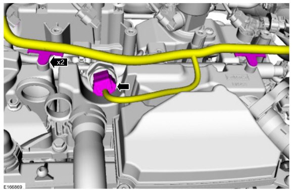
Detach the wiring harness retainers and disconnect the FRP sensor electrical connector.
 |
-
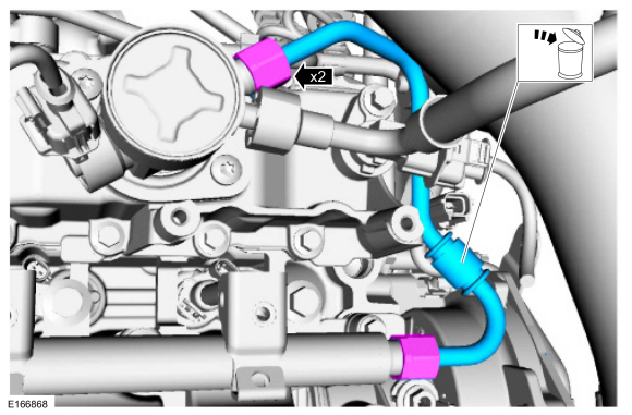
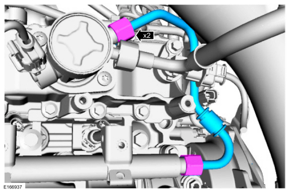
NOTICE: To release the fuel pressure in the high pressure fuel tube, wrap the high pressure fuel pump flare nut with a shop towel to absorb any residual fuel pressure during the loosening of high pressure fuel pump flare nut.
Disconnect the high-pressure fuel tube flare nuts. Remove and discard the high-pressure fuel tube.
 |
-
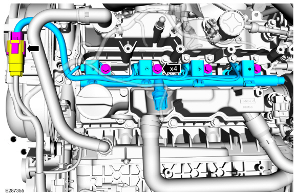
NOTICE: Pull out the fuel rail in the direction of the fuel injector axis or damage may occur to the fuel injectors.
NOTE: Use compressed air to remove any dirt or foreign material from the cylinder head, the block and the general surrounding area of the fuel rail and the fuel injectors.
NOTE: When removing the fuel rails, the fuel injectors may remain in the cylinder head and require the use of a Fuel Injector Remover tool to extract. Wiggling the fuel injector by hand to break it loose may allow the fuel injector to be removed by hand.
NOTE: Should any of the fuel injectors remain in the head, then the fuel injector electrical connectors will need to be disconnected as the fuel rail is being removed.
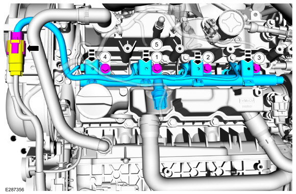
Disconnect the fuel injector main wire harness electrical connector, remove the fuel rail bolts, then remove the fuel rail.
 |
-
Disconnect the fuel injector electrical connectors, then remove the fuel injectors from the fuel rail.
 |
-
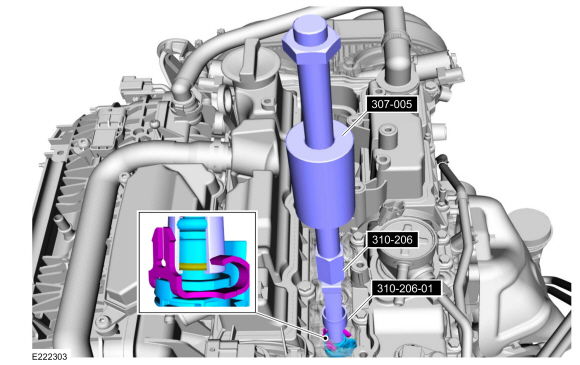
NOTICE: Use minimal force to remove the fuel injectors that remained in the cylinder head with the Fuel Injector Remover tool or damage to the fuel injector assembly may occur. Wiggling the injector by hand to break it loose may allow the injector to be removed by hand.
Remove any of the fuel injectors that remained in the cylinder head. Install the special tool 310-206 below the lip on the upper fuel injector body as pictured. Push the adapter tool 310-206-01 all of the way down to grip the fuel injector tightly, in order to keep the tool from slipping off of the fuel injector.
Use Special Service Tool: 307-005 (T59L-100-B) Slide Hammer. , 310-206 Remover, Fuel Injector. , 310-206-01 Adapter for 310-206.
 |
-
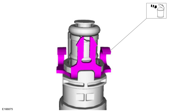
Remove and discard the fuel injector clips.
 |
-
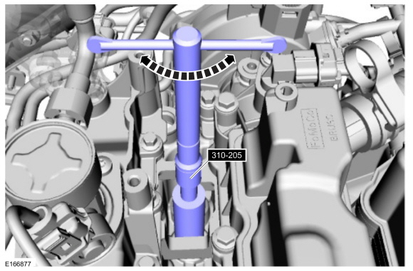
NOTICE: Do not use compressed air to clean the tip of the fuel injector.
NOTICE: Do not use a brush to clean the tip of the fuel injector.
NOTE: Make sure to thoroughly clean any residual fuel or foreign material from the cylinder head, block and the general surrounding area of the fuel rails and injectors.
Using the special tool, clean the cylinder head fuel injector bores.
Use Special Service Tool: 310-205 Fuel Injector Brush.
 |
Installation
-
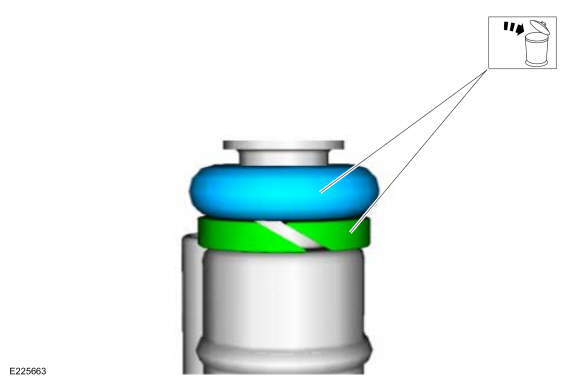
NOTE: Note the correct orientation of the fuel injector support rings for correct installation of the new fuel injector support rings.
-
Remove and discard the fuel injector O-rings.
-
Remove and discard the fuel injector support rings.
-
Remove and discard the fuel injector O-rings.
 |
-
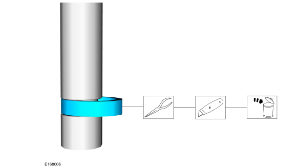
NOTICE: Use care when removing the lower Teflon® seals, not to scratch, nick or gouge the fuel injectors.
NOTICE: Do not attempt to cut the lower Teflon® seal without first pulling it away from the fuel injector or damage to the injector may occur.
-
Pull the lower Teflon® seal away from the injector with narrow tip pliers.
-
Carefully cut, remove and discard the lower fuel injector Teflon® seals.
-
Pull the lower Teflon® seal away from the injector with narrow tip pliers.
 |
-
NOTICE: Do not lubricate the new lower Teflon® fuel injector seals.
-
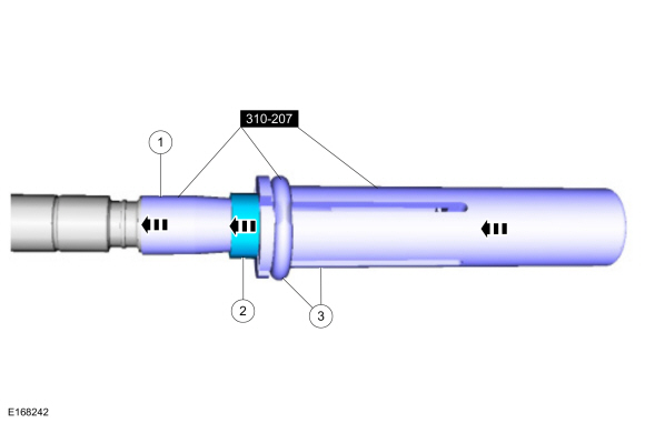
Install the Arbor (part of the Fuel Injector Seal Installer) on the fuel injector tips.
Use Special Service Tool: 310-207 Installer, Fuel Injector Seal Assembly.
-
NOTICE: Once the Teflon® seal is installed on the Teflon® Seal Guide, it should immediately be installed onto the fuel injector to avoid excessive expansion of the Teflon® seal.
NOTE: Make sure that new lower fuel injector Teflon® seals are installed.
Install the new Teflon® seals onto the Arbor, using the Pusher Tool (part of the Fuel Injector Seal Installer), slide the Teflon® seals along the Arbor.
-
Using the Pusher Tool, slide the Teflon® seals off
of the Teflon® Seal Guide and into the groove on the fuel injectors.
Use Special Service Tool: 310-207 Installer, Fuel Injector Seal Assembly.
-
Remove the special tools.
-
Install the Arbor (part of the Fuel Injector Seal Installer) on the fuel injector tips.
 |
-
NOTICE: Install the fuel injectors into the cylinder head within 15 minutes of sizing the seals due to Teflon® seal expansion.
NOTE: Make sure the Teflon® seal is fully seated in the groove on the fuel injector before sizing the Teflon® seal.
-
Massage and warm the Teflon® seal with your fingers
before the Teflon® seal sizer tool is installed. This will aid in
installing the Teflon® seal sizer tool.
-
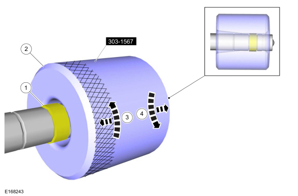
Position the Teflon® seal sizer tool with the larger
opening towards the Teflon® seal. Push while turning the Teflon® seal
sizer tool 180 degrees.
Use Special Service Tool: 303-1567 Sizer, Teflon Seal.
-
Once the Teflon® seal sizer tool is installed, check
and make sure the Teflon® seal is in the sizing portion of the Teflon®
seal sizer tool.
-
After one minute, turn the Teflon® seal sizer tool back 180 degrees and remove.
-
Massage and warm the Teflon® seal with your fingers
before the Teflon® seal sizer tool is installed. This will aid in
installing the Teflon® seal sizer tool.
 |
-
NOTICE: Use new fuel injector O-ring seals that are made of special fuel-resistant material. The use of ordinary O-ring seals may cause the fuel system to leak. Do not reuse the O-ring seals.
NOTICE: Do not lubricate the new lower Teflon® fuel injector seals.
-
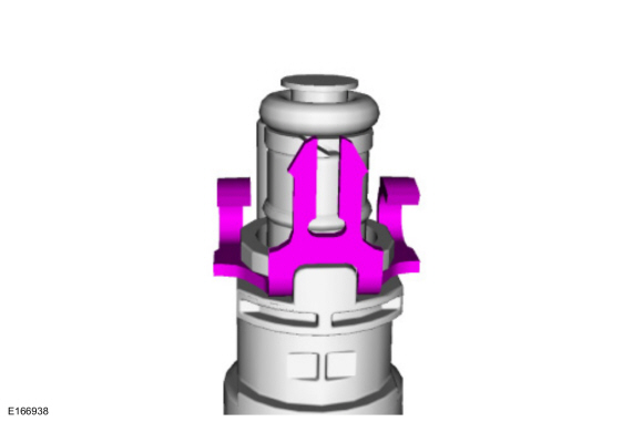
Install the new the fuel injector support rings as noted during removal.
-
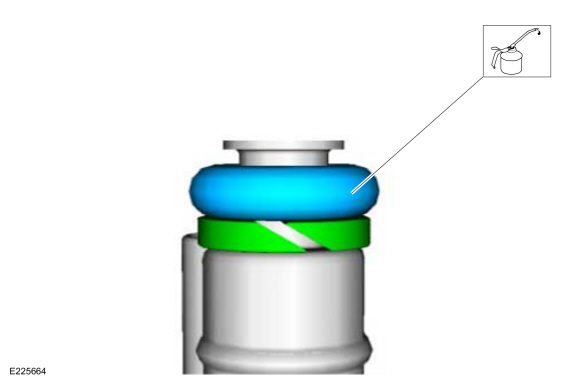
Install the new fuel injector O-rings and lubricate with clean engine oil.
-
Install the new the fuel injector support rings as noted during removal.
 |
-
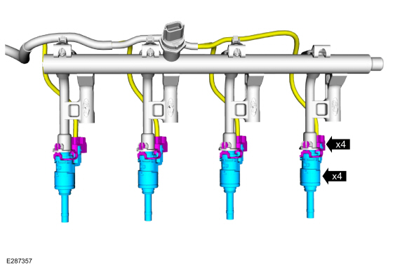
Install the new the fuel injector clips.
 |
-
NOTICE: The FRP sensor must be replaced only if it is removed from the fuel rail.
NOTE: The fuel injector clip must lock into the slot of the fuel rail cup.
Install the fuel injectors to the fuel rail, then connect the fuel injector electrical connectors.
Refer to: Fuel Rail Pressure (FRP) Sensor (303-14A Electronic Engine Controls - 1.5L EcoBoost (118kW/160PS) – I4, Removal and Installation).
 |
-
NOTICE: Do not lubricate the new lower Teflon® fuel injector seals.
NOTE: Only tighten the fuel rail bolts finger tight at this stage.
-
Install the fuel rail, push down on the fuel rail
above the injectors. Install and tighten the fuel rail bolts in the
sequence shown.
Torque: 17 lb.ft (23 Nm)
-
Connect the fuel injector main wire harness electrical connector.
-
Install the fuel rail, push down on the fuel rail
above the injectors. Install and tighten the fuel rail bolts in the
sequence shown.
 |
-
NOTICE: Make sure that a new high pressure fuel tube is installed.
NOTE: Only tighten the high pressure fuel tube flare nuts finger tight at this stage.
NOTE: Calculate the correct torque wrench setting for the following torque using the Torque Wrench Adapter Formulas.
Tighten the high-pressure fuel tube flare nuts in the following 3 stages.
Torque:
Stage 1: 15 lb.ft (21 Nm)
Stage 2: Wait 5 min
Stage 3: 15 lb.ft (21 Nm)
 |
-
Attach the wire harness retainers and connect the FRP electrical connector.
 |
-
Install the ignition coil-on-plugs.
Refer to: Ignition Coil-On-Plug (303-07A Engine Ignition - 1.5L EcoBoost (118kW/160PS) – I4, Removal and Installation).
-
Connect the battery.
Refer to: Battery Disconnect and Connect (414-01 Battery, Mounting and Cables, General Procedures).
-
Pressurize the fuel system.
Refer to: Fuel System Pressure Release (310-00A Fuel System - General Information - 1.5L EcoBoost (118kW/160PS) – I4, General Procedures).
 Fuel Pump Driver Module (FPDM). Removal and Installation
Removal
NOTE:
The fuel pump driver module is located behind the left C-pillar lower trim panel.
Remove the left C-pillar lower trim panel...
 High-Pressure Fuel Pump. Removal and Installation
Materials
Name
Specification
Engine Oil - SAE 5W-20 - Synthetic Blend Motor OilXO-5W20-Q1SP
WSS-M2C945-B1
Removal
NOTICE:
Do not loosen any fittings or plugs on the high-pressure fuel pump...
Other information:
Ford Fusion 2013–2020 Owners Manual: Adjusting the Headlamps
Vertical Aim Adjustment The headlamps on your vehicle are properly aimed at the assembly plant. If your vehicle has been in an accident, the alignment of your headlamps should be checked by your authorized dealer. Headlamp Aiming Target 8 feet (2...
Ford Fusion 2013–2020 Owners Manual: Front Fog Lamps (IF EQUIPPED)
Switching the Front Fog Lamps On or Off Only switch the front fog lamps on during reduced visibility. You can switch the front fog lamps on if any of the following occur: You set the lighting control to the parking lamps position. You set the lighting control to the headlamps position...
Categories
- Manuals Home
- 2nd Generation Ford Fusion Owners Manual
- 2nd Generation Ford Fusion Service Manual
- Starter Motor. Removal and Installation
- Intake Manifold. Removal and Installation
- Load Carrying
- New on site
- Most important about car
Child Safety Locks
When these locks are set, the rear doors cannot be opened from the inside.
