Ford Fusion: Front End Sheet Metal Repairs / Front Side Member and Fender Apron Panel LH. Removal and Installation
Special Tool(s) / General Equipment
| Resistance Spotwelding Equipment | |
| Hot Air Gun | |
| Air Body Saw | |
| 8 mm Drill Bit | |
| MIG/MAG Welding Equipment | |
| Spot Weld Drill Bit |
Materials
| Name | Specification |
|---|---|
| Metal Bonding Adhesive TA-1, TA-1-B, 3M™ 08115, LORD Fusor® 108B |
- |
| Seam Sealer TA-2-B, 3M™ 08308, LORD Fusor® 803DTM |
- |
Removal
-
Follow the health and safety precautions. WARNING:
Before beginning any service procedure in this
section, refer to Safety Warnings in section 100-00 General Information.
Failure to follow this instruction may result in serious personal
injury.
WARNING:
Before beginning any service procedure in this
section, refer to Safety Warnings in section 100-00 General Information.
Failure to follow this instruction may result in serious personal
injury.
Refer to: Health and Safety Precautions (100-00 General Information, Description and Operation).
-
Remove the following items.
Refer to: Fender Apron Panel Reinforcement (501-27 Front End Sheet Metal Repairs, Removal and Installation).
Refer to: Engine (303-01C Engine - 2.5L Duratec (125kW/170PS), Removal).
Refer to: Radiator (303-03B Engine Cooling - 2.0L EcoBoost (184kW/250PS) – MI4, Removal and Installation).
Refer to: Radiator (303-03C Engine Cooling - 2.5L Duratec (125kW/170PS), Removal and Installation).
Refer to: Instrument Panel (501-12 Instrument Panel and Console) .
Refer to: Front Impact Severity Sensor (501-20 Supplemental Restraint System) .
Refer to: A-Pillar Trim Panel (501-05 Interior Trim and Ornamentation) .
Refer to: Restraints Control Module (RCM) (501-20B Supplemental Restraint System, Removal and Installation).
Refer to: Front Seat (501-10A Front Seats, Removal and Installation).
-
Reposition the carpet and wiring harness away from the working area.
-
If Equipped - RH Side Only:
Remove the dampener.
 |
-
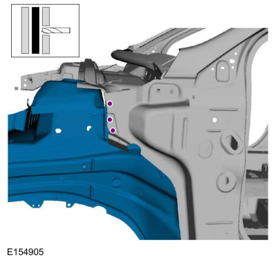
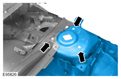
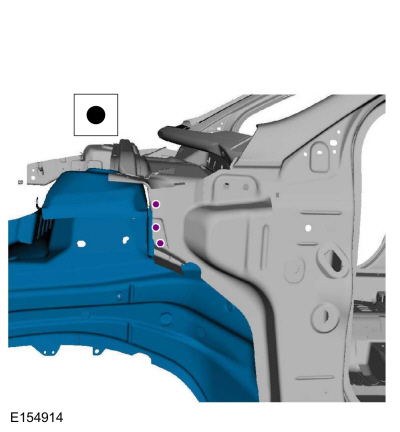
Drill out the spot welds.
Use the General Equipment: Spot Weld Drill Bit
 |
-
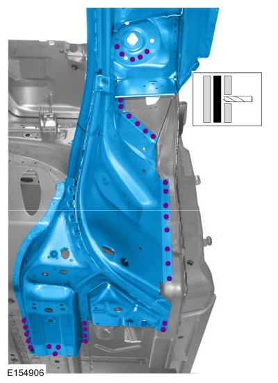
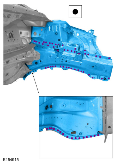
Drill out the spot welds.
Use the General Equipment: Spot Weld Drill Bit
 |
-
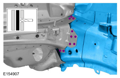
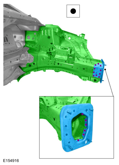
Drill out the spot welds and remove the front side member.
Use the General Equipment: Spot Weld Drill Bit
 |
-
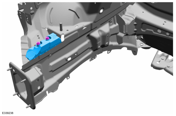
Drill out the spot welds.
Use the General Equipment: Spot Weld Drill Bit
 |
-
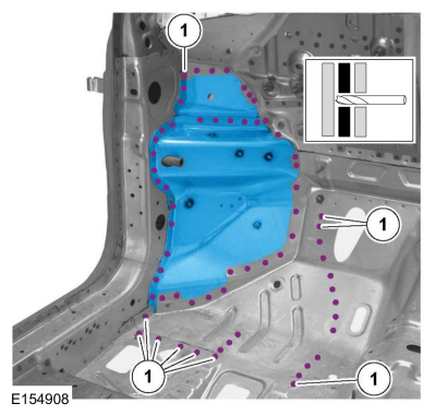
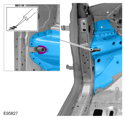
NOTE: A partial section needs to be cut out at the apron panel to remove side member with the apron panel.
Carefully cut the partial section from the apron panel.
Use the General Equipment: Air Body Saw
 |
-
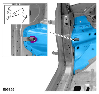
Remove the fender apron reinforcement panel.
Use the General Equipment: Hot Air Gun
 |
Installation
-
Assure correct placement of all components.
Refer to: Body and Frame (501-26 Body Repairs - Vehicle Specific Information and Tolerance Checks, Description and Operation).
-
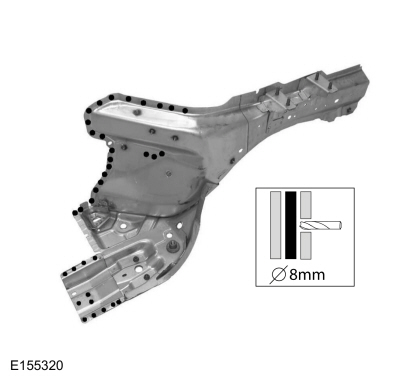
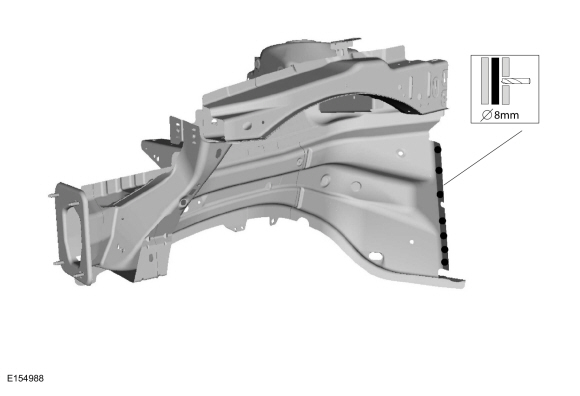
Drill plug welds holes in replacement panel.
Use the General Equipment: 8 mm Drill Bit
 |
-
NOTE: A partial section needs to be cut out at the apron panel to enable installation of the side member.
Carefully cut the partial section from the apron panel.
Use the General Equipment: Air Body Saw
 |
-
Drill plug welds holes in replacement panel.
Use the General Equipment: 8 mm Drill Bit
 |
-
Install the front side member and properly position.
 |
-
Refer to: Body and Frame (501-26 Body Repairs - Vehicle Specific Information and Tolerance Checks, Description and Operation).
-
Apply adhesive at the cut portion.
Material: Metal Bonding Adhesive / TA-1, TA-1-B, 3M™ 08115, LORD Fusor® 108B
 |
-
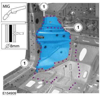
Install spot welds.
Use the General Equipment: MIG/MAG Welding Equipment
Use the General Equipment: 8 mm Drill Bit
 |
-
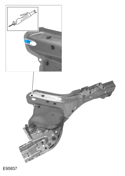
NOTE: In order to ensure that complete sealing is achieved, the remaining openings on the mount tube for the instrument panel bracket need to be sealed with body sealant.
Seam weld and apply sealant as indicated.
Use the General Equipment: MIG/MAG Welding Equipment
Material: Seam Sealer / TA-2-B, 3M™ 08308, LORD Fusor® 803DTM
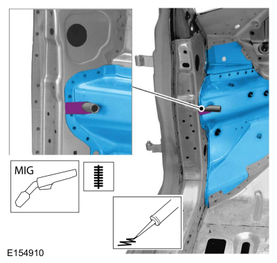 |
-
Install plug welds.
Use the General Equipment: MIG/MAG Welding Equipment
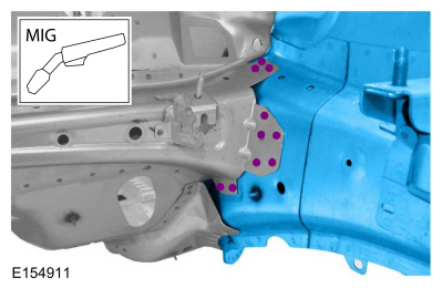 |
-
Install spot welds.
Use the General Equipment: Resistance Spotwelding Equipment
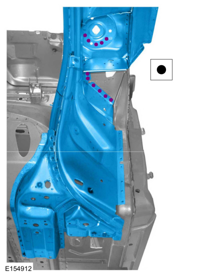 |
-
Install plug welds.
Use the General Equipment: MIG/MAG Welding Equipment
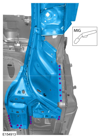 |
-
Install spot welds.
Use the General Equipment: Resistance Spotwelding Equipment
 |
-
Install spot welds.
Use the General Equipment: Resistance Spotwelding Equipment
 |
-
Install the bumper bracket and spot weld.
Use the General Equipment: Resistance Spotwelding Equipment
 |
-
Finish the repair area using typical metal finishing procedures.
-
Sealing work: All areas must be sealed to production level.
Material: Seam Sealer / TA-2-B, 3M™ 08308, LORD Fusor® 803DTM
-
Refinish using a Ford Motor Company approved paint system.
-
If Equipped - RH Side Only:
Install the dampener.
 |
-
Restore corrosion protection.
Refer to: Corrosion Prevention (501-25 Body Repairs - General Information, General Procedures).
-
Reposition the carpet and wiring harness.
-
Install the following items.
Refer to: Fender Apron Panel Reinforcement (501-27 Front End Sheet Metal Repairs, Removal and Installation).
Refer to: Engine (303-01C Engine - 2.5L Duratec (125kW/170PS), Installation).
Refer to: Radiator (303-03B Engine Cooling - 2.0L EcoBoost (184kW/250PS) – MI4, Removal and Installation).
Refer to: Radiator (303-03C Engine Cooling - 2.5L Duratec (125kW/170PS), Removal and Installation).
Refer to: Instrument Panel (501-12 Instrument Panel and Console) .
Refer to: Front Impact Severity Sensor (501-20 Supplemental Restraint System) .
Refer to: A-Pillar Trim Panel (501-05 Interior Trim and Ornamentation) .
Refer to: Restraints Control Module (RCM) (501-20B Supplemental Restraint System, Removal and Installation).
Refer to: Front Seat (501-10A Front Seats, Removal and Installation).
 Front Side Member Extension. Removal and Installation
Removal
NOTE:
Left hand (LH) side shown, right hand (RH) side similar.
Remove the underbody shields.
Remove the front crossmember...

Other information:
Ford Fusion 2013–2020 Service Manual: Rear Parking Aid Sensor. Removal and Installation
Removal NOTE: Removal steps in this procedure may contain installation details. Remove the rear bumper cover. Refer to: Rear Bumper Cover (501-19 Bumpers, Removal and Installation). Disconnect the rear parking aid sensor harness from the rear bumper cover reinforcement. Remove the retainers, release the tabs and remove the rear bumper cover reinfor..
Ford Fusion 2013–2020 Owners Manual: Cross Traffic Alert (IF EQUIPPED)
WARNING: Do not use the cross traffic alert system as a replacement for using the interior and exterior mirrors or looking over your shoulder before reversing out of a parking space. The cross traffic alert system is not a replacement for careful driving. WARNING: The system may not operate properly during severe weather conditions, for example snow, ice, heavy rain and spray. Always driv..
Categories
- Manuals Home
- 2nd Generation Ford Fusion Owners Manual
- 2nd Generation Ford Fusion Service Manual
- Body Control Module (BCM). Removal and Installation
- Transmission - 1.5L EcoBoost (118kW/160PS) – I4. Removal and Installation
- Traction Control
- New on site
- Most important about car
Adjusting the Steering Wheel
WARNING: Do not adjust the steering wheel when your vehicle is moving.
Note: Make sure that you are sitting in the correct position.