Ford Fusion: Front Seats / Front Seats - System Operation and Component Description. Description and Operation
System Operation
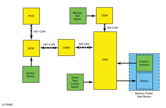
System Diagram - Memory Seat
.jpg)
| Item | Description |
|---|---|
| 1 | Memory Power Seat Motors |
| 2 | HS1-CAN |
| 3 | PCM |
| 4 | BCM |
| 5 | HS1-CAN |
| 6 | Ignition Switch |
| 7 | GWM |
| 8 | Memory SET Switch |
| 9 | Driver Seat Control Switch |
| 10 | MS-CAN |
| 11 | DSM |
| 12 | MS-CAN |
| 13 | DDM |
| 14 | Position Sensors |
| 15 | Motors |
Network Message Chart - Memory Seat
DSM Network Input Messages
| Broadcast Message | Originating Module | Message Purpose |
|---|---|---|
| Key-in-ignition status | BCM | Provides the ignition position. This input is used for the easy entry/exit feature. |
| Personality recall | BCM | When the personality recall command is received from the BCM, the DSM stores or recalls the associated memory seat position (1 or 2). If a RKE transmitter has been programmed to a memory position, this input is used to recall the associated memory seat position. To program the RKE transmitter, REFER to the Owner's Literature. |
| Memory seat switch status | DDM | When the memory set switch (1 or 2) is activated, the DDM sends this message to the DSM, which then stores or recalls the associated memory seat position. |
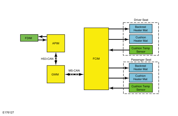
System Diagram - Heated Seats
.jpg)
| Item | Description |
|---|---|
| 1 | FDIM |
| 2 | APIM |
| 3 | HS3-CAN |
| 4 | GWM |
| 5 | MS-CAN |
| 6 | FCIM |
| 7 | Driver Seat |
| 8 | Backrest Heater Mat |
| 9 | Cushion Heater Mat |
| 10 | Cushion Temp Sensor |
| 11 | Passenger Seat |
| 12 | Backrest Heater Mat |
| 13 | Cushion Heater Mat |
| 14 | Cushion Temp Sensor |
Network Message Chart - Heated Seats
FCIM Network Input Messages
| Broadcast Message | Originating Module | Message Purpose |
|---|---|---|
| Climate control requests | FCIM | The climate control requests message contains the heated seat request information. |
FDIM Network Input Messages
| Broadcast Message | Originating Module | Message Purpose |
|---|---|---|
| Climate control button status | FCIM | The climate control button status message provides the current status of the heated seat button(s) to the FCIM for the purpose of updating the displayed status of the heated seat buttons on the FDIM (touchscreen). |
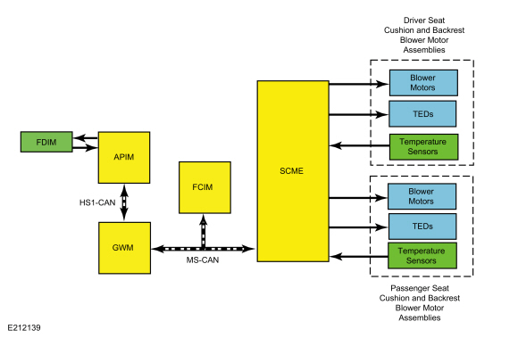
System Diagram - Climate Controlled Seats
.jpg)
| Item | Description |
|---|---|
| 1 | FDIM |
| 2 | APIM |
| 3 | HS3-CAN |
| 4 | GWM |
| 5 | MS-CAN |
| 6 | SCME |
| 7 | TEDs |
| 8 | TEDs |
| 9 | FCIM |
| 10 | Blower Motors |
| 11 | Passenger Seat Cushion and Backrest Blower Motor Assemblies |
| 12 | Temperature Sensors |
| 13 | Driver Seat Cushion and Backrest Blower Motor Assemblies |
| 14 | Temperature Sensors |
| 15 | Blower Motors |
Network Message Chart - Climate Controlled Seats
SCME Network Input Messages
| Broadcast Message | Originating Module | Message Purpose |
|---|---|---|
| Climate control requests | FDIM | The climate control requests message contains the climate controlled seat request information. |
| Climate control requests | FCIM | The climate control requests message contains the climate controlled seat request information. |
FCIM Network Input Messages
| Broadcast Message | Originating Module | Message Purpose |
|---|---|---|
| Climate control button status | SCME | The SCME provides this message to the FCIM for the purpose of updating the displayed status of the climate controlled seat buttons on the FCIM. |
FDIM Network Input Messages
| Broadcast Message | Originating Module | Message Purpose |
|---|---|---|
| Climate control button status | SCME | The SCME provides this message to the FDIM for the purpose of updating the displayed status of the climate controlled seat buttons on the FDIM (touchscreen). |
Memory Seat Operation
The driver seat control switch provides a voltage signal to the DSM only when activated. This voltage signal causes the DSM to power the appropriate motor until the input is removed. The motor circuits are normally grounded through the DSM. The DSM internally switches the appropriate circuit from ground to voltage to operate the motors.
As the seat is adjusted, the DSM monitors the motor position sensors to record the current seat position. The DSM removes voltage from the motor upon termination of the seat control switch input or if the DSM does not detect movement from the motor while monitoring the position sensor during a memory recall operation.
If the DSM loses the signal from any of the motor position sensors, the affected seat motor operates in jog mode. Jog mode allows limited operation of the affected seat motor using only the seat control switch. When the seat control switch is operated in jog mode, the seat moves in the desired direction for one second, then stops. The seat control switch must be released, then pressed again in order to move the seat for an additional second. Jog mode is an indication that there is a seat motor sensor fault.
DSM Hard Stop/Soft Stop
A hard stop occurs when one of the memory seat track or backrest axes physically reach the end of travel and can go no further. A soft stop occurs when the seat stops before it physically reaches the end of travel. The hard stop is set by seat design and cannot be changed or adjusted. The soft stop is set by the DSM. The seat track axes are forward/rearward, front up/down and rear up/down. The backrest axis is recline forward/backward. To prevent unnecessary stress on the seat and motors, the DSM sets soft stop positions, 2 for each moving axis. The DSM uses a preset distance from the hard stop to determine where the soft stop occurs. When an axis reaches the hard stop and the switch is held for approximately one second, the DSM briefly reverses direction and establishes the soft stop for that axis in that direction. The DSM uses this back up strategy to check sensor integrity any time movement has stopped prematurely due to a sensor failure or obstruction.
Easy Entry/Exit
The easy entry/exit feature is a function of the DSM that moves the driver seat back approximately 50.8 mm (2 in) (unless seat is already positioned at or near the end of travel) when the ignition is turned off. The DSM receives ignition off status over the MS-CAN and operates the driver seat rearward. The DSM cancels this operation if a valid input command is received from the driver seat control switch, memory set switch, exterior mirror control switch or if the function has been disabled.
The DSM records the current seat positions before operating the seat for an easy exit operation. During easy entry operation (when the ignition is turned on), the seat is returned to the recorded seat position prior to the easy exit operation. Easy entry operation is cancelled if a valid input command is received by the DSM. A memory position recall using the memory set switch also overrides the easy exit operation.
The easy entry/exit feature can be enabled/disabled on the message center. For information on programming vehicle settings in the message center, refer to the Owner's Literature.
Power Seat Operation - Passenger and Driver (Without Memory)
The seat control switches contain normally-closed contacts which are grounded. An individual circuit is switched to voltage when a specific adjustment position is selected. The seat control switches are hard-wired directly to the applicable seat motors. The motor direction is determined by the polarity of voltage supplied from the seat control switch.
Heated Seat Operation
The driver and passenger heated seat control buttons and indicators are located on the FCIM and FDIM (touchscreen, if equipped). The heated seat system functions independently of the vehicle's climate control system. Each time the heated seat button is pressed, the system decreases one setting (the sequence is high, med, low, off, high, etc.).
When activated, the FCIM supplies voltage to the selected seat heater circuit. Each seat cushion heater mat and backrest heater mat is connected in a series circuit to the FCIM and powered by the output circuit for that seat. The FCIM monitors inputs from a temperature sensor located in each seat cushion heater mat, and maintains seat temperature by cycling the heater circuits on/off. The heated seat remains ON until the heated seat switch button is pressed to cycle the FCIM OFF or the ignition is set to OFF.
If a fault is detected by the FCIM, the module stops supplying voltage to that individual left or right seat that the fault was detected on until the ignition is turned OFF and then ON.
Climate Controlled Seat Operation
The driver and passenger climate controlled seat buttons are selected from the FCIM and FDIM (touchscreen). The climate controlled seat system functions independently from the vehicle's climate control system.
The seat cushion and backrest are each equipped with a blower motor assembly. As cabin air is drawn through each blower motor, the blower motors heat or cool the air, which is then directed into the foam pad where it is distributed along the surface of the cushion and backrest of the seat. Once the system is activated, the SCME uses a set of flexible algorithms to control the heating/cooling modes and the blower speed dependant on the commanded climate controlled seat settings.
The SCME monitors seat cushion temperature while it supplies voltage and ground to both blower motors. The SCME also supplies a variable voltage signal to control the blower speed. Cabin air enters the blower through a filter attached to the blower motor housing. Heated or cooled air exits the blower motor and flows through the foam pad.
Climate Controlled Seat Heating Characteristics
- In heat mode, the blower motor can add up to 40–60° C (72–108° F) to the ambient inlet air temperature.
- The system control settings are indicated next to each climate controlled seat heat switch button on the touchscreen. The first setting is HIGH (3 indicators), the second setting is MED (2 indicators) and the third is LOW (1 indicator) then OFF (no indicators).
- When heating, the SCME varies the speed of the blower motors and the duty cycle of the integral Thermo-Electric Device (TED) in order to reach and maintain the desired temperature determined by the system control settings.
Climate Controlled Seat Cooling Characteristics
- In cool mode, the blower motors can remove up to 8° C (14° F) from the ambient air temperature entering the system.
- The system control settings are based on the 3 indicators next to each climate controlled seat cool switch button on the touchscreen. The first setting is HIGH (3 indicators), the second setting is MED (2 indicators) and the third is LOW (1 indicator) then OFF (no indicators).
- When cooling, the SCME maintains a constant blower motor speed and a constant Thermo-Electric Device (TED) supply voltage (duty cycle is determined by the switch setting) in COOL mode.
Climate Controlled Seat Recovery Mode
NOTE: The presence of overtemperature faults (Diagnostic Trouble Codes (DTCs) B1153:4B, B1154:4B, B1151:4B and B1152:4B) can be induced by incorrectly operating the climate controlled seat system after an initial heat setting has been attained. If a heat setting is repeatedly turned off and on in an attempt to increase the seat temperature or repeatedly toggled between heat and cool modes, an overtemperature condition can result and the Diagnostic Trouble Codes (DTCs) may be set.
If the temperature of one of the blower motors rises above 110° C (229.8° F) in the heat mode or 65° C (148.9° F) in the cool mode for more than 4 seconds, the SCME records an overtemperature DTC, removes voltage from the Thermo-Electric Devices (TEDs) (part of the blower motor assembly) and goes into recovery mode (blower only) for 30 seconds to cool down the Thermo-Electric Devices (TEDs). The same occurs if a temperature difference of 60° C (108° F) or greater is detected between the backrest and cushion blower motors on either front seat. The SCME continues to monitor the Thermo-Electric Devices (TEDs) while in recovery mode. If the temperature of the Thermo-Electric Devices (TEDs) does not drop to 105° C (220.8° F) in the heat mode or 60° C (139.9° F) in the cool mode after 30 seconds, the system continues to cool the Thermo-Electric Devices (TEDs) in recovery mode for up to 5 minutes. If the Thermo-Electric Devices (TEDs) cool down after 30 seconds, but before 5 minutes (checked at 4 second intervals), the system is operating normally. An overtemperature DTC is still recorded even if the system recovers and is operating normally. This is more likely to occur during extreme cabin temperatures with significant seat back sun load. If the system does not recover within 30 seconds in heat mode or within 5 minutes in cool mode, the SCME disables that seat (fault mode) and remains off until that feature is reactivated by the customer. Also, if the SCME detects a temperature differential fault twice during the same ignition cycle, the SCME disables the seat. When a fault causes a shutdown, the climate controlled seat indicators turn off and that seat is not operational until the next ignition cycle.
Remote Start Climate Operation
Different climate control modes/preferences can be selected when the vehicle is started using the remote start feature. This can be accessed through the message center. For additional information on how to set the remote start preferences, refer to the Owner's Literature. When the driver seat and/or passenger seat is set to AUTO mode, the driver/passenger heated/climate controlled seat activates in full heat mode when the outside temperature is less than 0° C (32° F) and full cool mode (climate controlled seats only) when outside temperature is greater than 27° C (80° F) any time the vehicle is started using the remote start feature. No heated/climate controlled seat adjustments are recognized during remote start operation. Once the ignition is cycled ON, the heated/climate controlled seat turns off.
Component Description
Seat Control Switch - Without Memory
The seat control switch contains normally closed contacts (which are grounded). When a specific adjustment position is selected, an individual circuit is switched to voltage.
Seat Control Switch - With Memory
The seat control switch is hard-wired to the DSM, which controls seat operation. When a specific seat adjustment position is selected, an individual circuit is switched to voltage.
DSM
The driver seat control switch and power memory seat motors are hard-wired to the DSM. The DSM controls the operation of the power memory seat. The DSM communicates on the MS-CAN. The SCME is integral to the DSM. PMI is required on both the DSM and the SCME when a new DSM is installed. The DSM hard stop/soft stops must be set/reset any time a new DSM, driver seat track or driver seat backrest is installed.
Memory Set Switch
The memory set switch (part of the driver door lock switch assembly) contains 2 momentary contact switches. It is hard-wired to the DDM and is used to recall 1 of 2 memory positions stored in the DSM.
Driver Seat Track - Without Memory
There are 3 front seat track bi-directional motors present on power seat tracks. The horizontal (fore/aft) front seat track motor is the only seat track motor which can be serviced separately from the seat track assembly. All other seat track motors (front height, rear height) are serviced as part of the seat track assembly. The seat track motors move the power seat forward/backward and up/down depending on the polarity of voltage supplied from the seat control switch.
Driver Seat Track - With Memory
There are 3 front seat track bi-directional motors present on power seat tracks. The horizontal (fore/aft) front seat track motor is the only seat track motor which can be serviced separately from the seat track assembly. All other seat track motors (front height, rear height) are serviced as part of the seat track assembly. Each seat track motor contains a Hall-effect sensor which provides seat track position information to the DSM for setting/obtaining desired preset seat memory positions. The seat track motors move the power seat forward/backward and up/down depending on the polarity of voltage supplied from the DSM.
Passenger Seat Track
The 6-way passenger power seat is equipped with 2 front seat track bi-directional motors. The horizontal (fore/aft) front seat track motor is the only seat track motor which can be serviced separately from the seat track assembly. The height motor is serviced as part of the seat track assembly. The seat track motors move the power seat forward/backward and up/down depending on the polarity of voltage supplied from the seat control switch.
The 10-way passenger power seat is equipped with 3 front seat track bi-directional motors. The horizontal (fore/aft) front seat track motor is the only seat track motor which can be serviced separately from the seat track assembly. All other seat track motors (front height, rear height) are serviced as part of the seat track assembly. The seat track motors move the power seat forward/backward and up/down depending on the polarity of voltage supplied from the seat control switch.
Driver Seat Backrest - Without Memory
The seat backrest contains a bi-directional motor which is integral to the seat backrest assembly. The seat backrest motor moves the seat backrest forward/backward depending on the polarity of voltage supplied from the seat control switch.
Driver Seat Backrest - With Memory
The seat backrest contains a bi-directional motor which is integral to the seat backrest assembly. The seat backrest motor contains a Hall-effect sensor which provides seat backrest position information to the DSM for setting/obtaining desired preset seat memory positions. The seat backrest motor moves the seat backrest forward/backward depending on the polarity of voltage supplied from the DSM.
Passenger Seat Backrest
The seat backrest contains a bi-directional motor which is integral to the seat backrest assembly. The seat backrest motor moves the seat backrest forward/backward depending on the polarity of voltage supplied from the seat control switch.
Front Seat Power Lumbar Assembly
The front seat power lumbar assembly is mounted to the backrest (serviced as an assembly).
FDIM
If equipped, the FDIM (touchscreen) contains the heated and climate controlled seat buttons.
FCIM
The FCIM contains the heated seat or climate seat control buttons. If equipped with heated seats, the FCIM monitors the seat cushion temperature sensor and supplies heater current to the seat cushion and backrest heater mats until the desired setpoint temperature is reached. Once the setpoint temperature is reached, the FCIM cycles the heater circuits on/off as required to maintain the setpoint temperature.
Heater Mat
If equipped with heated seats, the cushion heater mats are each equipped with a temperature sensor (thermistor) which provides feedback to the FCIM. The cushion and backrest heater mats are connected in series.
SCME
If equipped with climate controlled seats, the SCME controls the operation of the climate controlled seat system. The SCME is integral to the DSM. PMI is required on both the DSM and the SCME when a new DSM is installed.
Blower Motor
If equipped with climate controlled seats, the seat cushion and backrest are each equipped with a blower motor assembly (Thermo-Electric Device (TED) and fan motor, serviced as an assembly). There is also a temperature sensor (thermistor) in each blower motor which provides feedback to the SCME. The blower motor assembly is controlled by the SCME.
 Front Seats - Overview. Description and Operation
Overview
Driver Power Seat - Without Memory
The
seat control switch contains normally closed contacts which are
grounded. An individual circuit is switched to voltage when a specific
adjustment position is selected...
 Front Seats. Diagnosis and Testing
DTC Chart: DDM
Diagnostics in this manual assume a certain skill level and knowledge of Ford-specific diagnostic practices. REFER to: Diagnostic Methods (100-00 General Information, Description and Operation)...
Other information:
Ford Fusion 2013–2020 Service Manual: Roof Side Rail. Removal and Installation
Special Tool(s) / General Equipment Resistance Spotwelding Equipment Spherical Cutter Hot Air Gun Air Body Saw 8 mm Drill Bit MIG/MAG Welding Equipment Spot Weld Drill Bit Locking Pliers Materials Name Specification Seam SealerTA-2-B, 3M™ 08308, LORD Fusor® 803DTM - Flexible Foam Repair3M™ 08463, LORD Fusor® 121 - ..
Ford Fusion 2013–2020 Owners Manual: Engine Oil Dipstick - 1.5L EcoBoost™. Engine Oil Dipstick - 2.0L EcoBoost™/2.5L/2.7L EcoBoost™. Engine Oil Check
Engine Oil Dipstick - 1.5L EcoBoost™ Minimum. Maximum. Engine Oil Dipstick - 2.0L EcoBoost™/2.5L/2.7L EcoBoost™ Minimum. Nominal. Maximum. Engine Oil Check To check the engine oil level consistently and accurately, do the following: Make sure the parking brake is on. Make sure the transmission is in park (P) or neutral (N). Run the engine until it reaches normal operatin..
Categories
- Manuals Home
- 2nd Generation Ford Fusion Owners Manual
- 2nd Generation Ford Fusion Service Manual
- Powertrain
- Electronic Parking Brake (EPB) Service Mode Activation and Deactivation. General Procedures
- Memory Function
- New on site
- Most important about car
Power Door Locks
The power door lock control is on the driver and front passenger door panels.