Ford Fusion: Front Seats / Front Seats. Diagnosis and Testing
DTC Chart: DDM
Diagnostics in this manual assume a certain skill level and knowledge of Ford-specific diagnostic practices.
REFER to: Diagnostic Methods (100-00 General Information, Description and Operation).
DDM
DTC Chart
|
DTC
|
Description
|
Action
|
|
B1C03:23
|
Memory #1 Switch: Signal Stuck Low
|
GO to Pinpoint Test G
|
|
B1C04:23
|
Memory #2 Switch: Signal Stuck Low
|
GO to Pinpoint Test G
|
|
All other Diagnostic Trouble Codes (DTCs)
|
-
|
REFER to: Locks, Latches and Entry Systems (501-14 Handles, Locks, Latches and Entry Systems, Diagnosis and Testing).
|
DTC Chart: DSM
Diagnostics in this manual assume a certain skill level and knowledge of Ford-specific diagnostic practices.
REFER to: Diagnostic Methods (100-00 General Information, Description and Operation).
DSM
DTC Chart
|
DTC
|
Description
|
Action
|
|
B1298:24
|
Steering Column Adjust Up Switch: Signal Stuck High
|
REFER to: Steering Column (211-04 Steering Column, Diagnosis and Testing).
|
|
B1299:24
|
Steering Column Adjust Down Switch: Signal Stuck High
|
REFER to: Steering Column (211-04 Steering Column, Diagnosis and Testing).
|
|
B12A1:24
|
Steering Column Adjust Out Switch: Signal Stuck High
|
REFER to: Steering Column (211-04 Steering Column, Diagnosis and Testing).
|
|
B12A2:24
|
Steering Column Adjust In Switch: Signal Stuck High
|
REFER to: Steering Column (211-04 Steering Column, Diagnosis and Testing).
|
|
B12A7:11
|
Steering Column Tilt Sensor A: Circuit Short To Ground
|
REFER to: Steering Column (211-04 Steering Column, Diagnosis and Testing).
|
|
B12A7:12
|
Steering Column Tilt Sensor A: Circuit Short To Battery
|
REFER to: Steering Column (211-04 Steering Column, Diagnosis and Testing).
|
|
B12A8:11
|
Steering Column Telescope Sensor A: Circuit Short To Ground
|
REFER to: Steering Column (211-04 Steering Column, Diagnosis and Testing).
|
|
B12A8:12
|
Steering Column Telescope Sensor A: Circuit Short To Battery
|
REFER to: Steering Column (211-04 Steering Column, Diagnosis and Testing).
|
|
B1375:09
|
Steering Column Tilt Motor: Component Failure
|
REFER to: Steering Column (211-04 Steering Column, Diagnosis and Testing).
|
|
B1375:11
|
Steering Column Tilt Motor: Circuit Short To Ground
|
REFER to: Steering Column (211-04 Steering Column, Diagnosis and Testing).
|
|
B1375:12
|
Steering Column Tilt Motor: Circuit Short To Battery
|
REFER to: Steering Column (211-04 Steering Column, Diagnosis and Testing).
|
|
B1375:13
|
Steering Column Tilt Motor: Circuit Open
|
REFER to: Steering Column (211-04 Steering Column, Diagnosis and Testing).
|
|
B1375:1A
|
Steering Column Tilt Motor: Circuit Resistance Below Threshold
|
REFER to: Steering Column (211-04 Steering Column, Diagnosis and Testing).
|
|
B1375:31
|
Steering Column Tilt Motor: No Signal
|
REFER to: Steering Column (211-04 Steering Column, Diagnosis and Testing).
|
|
B137E:09
|
Steering Column Telescope Motor: Component Failure
|
REFER to: Steering Column (211-04 Steering Column, Diagnosis and Testing).
|
|
B137E:11
|
Steering Column Telescope Motor: Circuit Short To Ground
|
REFER to: Steering Column (211-04 Steering Column, Diagnosis and Testing).
|
|
B137E:12
|
Steering Column Telescope Motor: Circuit Short To Battery
|
REFER to: Steering Column (211-04 Steering Column, Diagnosis and Testing).
|
|
B137E:13
|
Steering Column Telescope Motor: Circuit Open
|
REFER to: Steering Column (211-04 Steering Column, Diagnosis and Testing).
|
|
B137E:1A
|
Steering Column Telescope Motor: Circuit Resistance Below Threshold
|
REFER to: Steering Column (211-04 Steering Column, Diagnosis and Testing).
|
|
B137E:31
|
Steering Column Telescope Motor: No Signal
|
REFER to: Steering Column (211-04 Steering Column, Diagnosis and Testing).
|
|
B14C3:24
|
Seat Height Rear Down Switch: Signal Stuck High
|
GO to Pinpoint Test F
|
|
B14C4:24
|
Seat Height Rear Up Switch: Signal Stuck High
|
GO to Pinpoint Test F
|
|
B14CB:11
|
Seat Height Rear Position Feedback: Circuit Short To Ground
|
GO to Pinpoint Test G
|
|
B14CB:12
|
Seat Height Rear Position Feedback: Circuit Short To Battery
|
GO to Pinpoint Test G
|
|
B14CE:09
|
Seat Horizontal Motor Output: Component Failure
|
GO to Pinpoint Test F
|
|
B14CE:11
|
Seat Horizontal Motor Output: Circuit Short To Ground
|
GO to Pinpoint Test F
|
|
B14CE:12
|
Seat Horizontal Motor Output: Circuit Short To Battery
|
GO to Pinpoint Test F
|
|
B14CE:14
|
Seat Horizontal Motor Output: Circuit Short To Ground or Open
|
GO to Pinpoint Test F
|
|
B14CE:15
|
Seat Horizontal Motor Output: Circuit Short To Battery or Open
|
GO to Pinpoint Test F
|
|
B14CE:1A
|
Seat Horizontal Motor Output: Circuit Resistance Below Threshold
|
GO to Pinpoint Test F
|
|
B14CE:31
|
Seat Horizontal Motor Output: No Signal
|
GO to Pinpoint Test G
|
|
B14CF:09
|
Seat Recline Motor Output: Component Failure
|
GO to Pinpoint Test F
|
|
B14CF:11
|
Seat Recline Motor Output: Circuit Short To Ground
|
GO to Pinpoint Test F
|
|
B14CF:12
|
Seat Recline Motor Output: Circuit Short To Battery
|
GO to Pinpoint Test F
|
|
B14CF:14
|
Seat Recline Motor Output: Circuit Short To Ground or Open
|
GO to Pinpoint Test F
|
|
B14CF:15
|
Seat Recline Motor Output: Circuit Short To Battery or Open
|
GO to Pinpoint Test F
|
|
B14CF:1A
|
Seat Recline Motor Output: Circuit Resistance Below Threshold
|
GO to Pinpoint Test F
|
|
B14CF:31
|
Seat Recline Motor Output: No Signal
|
GO to Pinpoint Test G
|
|
B14D0:09
|
Seat Height Front/Tilt Motor Output: Component Failure
|
GO to Pinpoint Test F
|
|
B14D0:11
|
Seat Height Front/Tilt Motor Output: Circuit Short To Ground
|
GO to Pinpoint Test F
|
|
B14D0:12
|
Seat Height Front/Tilt Motor Output: Circuit Short To Battery
|
GO to Pinpoint Test F
|
|
B14D0:14
|
Seat Height Front/Tilt Motor Output: Circuit Short To Ground or Open
|
GO to Pinpoint Test F
|
|
B14D0:15
|
Seat Height Front/Tilt Motor Output: Circuit Short To Battery or Open
|
GO to Pinpoint Test F
|
|
B14D0:1A
|
Seat Height Front/Tilt Motor Output: Circuit Resistance Below Threshold
|
GO to Pinpoint Test F
|
|
B14D0:31
|
Seat Height Front/Tilt Motor Output: No Signal
|
GO to Pinpoint Test G
|
|
B14D2:09
|
Seat Height Rear Motor Output: Component Failure
|
GO to Pinpoint Test F
|
|
B14D2:11
|
Seat Height Rear Motor Output: Circuit Short To Ground
|
GO to Pinpoint Test F
|
|
B14D2:12
|
Seat Height Rear Motor Output: Circuit Short To Battery
|
GO to Pinpoint Test F
|
|
B14D2:14
|
Seat Height Rear Motor Output: Circuit Short To Ground or Open
|
GO to Pinpoint Test F
|
|
B14D2:15
|
Seat Height Rear Motor Output: Circuit Short To Battery or Open
|
GO to Pinpoint Test F
|
|
B14D2:1A
|
Seat Height Rear Motor Output: Circuit Resistance Below Threshold
|
GO to Pinpoint Test F
|
|
B14D2:31
|
Seat Height Rear Motor Output: No Signal
|
GO to Pinpoint Test G
|
|
B1B89:11
|
Seat Slide Motor Speed/Position Sensor: Circuit Short To Ground
|
GO to Pinpoint Test G
|
|
B1B89:12
|
Seat Slide Motor Speed/Position Sensor: Circuit Short To Battery
|
GO to Pinpoint Test G
|
|
B1B91:11
|
Seat Tilt Motor Speed/Position Sensor: Circuit Short To Ground
|
GO to Pinpoint Test G
|
|
B1B91:12
|
Seat Tilt Motor Speed/Position Sensor: Circuit Short To Battery
|
GO to Pinpoint Test G
|
|
B1B93:11
|
Seat Recline Motor Speed/Position Sensor: Circuit Short To Ground
|
GO to Pinpoint Test G
|
|
B1B93:12
|
Seat Recline Motor Speed/Position Sensor: Circuit Short To Battery
|
GO to Pinpoint Test G
|
|
B1B96:24
|
Seat Slide Forward Switch: Signal Stuck High
|
GO to Pinpoint Test F
|
|
B1B97:24
|
Seat Slide Backward Switch: Signal Stuck High
|
GO to Pinpoint Test F
|
|
B1B98:24
|
Seat Tilt Up Switch: Signal Stuck High
|
GO to Pinpoint Test F
|
|
B1B99:24
|
Seat Tilt Down Switch: Signal Stuck High
|
GO to Pinpoint Test F
|
|
B1C00:24
|
Seat Recline Up Switch: Signal Stuck High
|
GO to Pinpoint Test F
|
|
B1C01:24
|
Seat Recline Down Switch: Signal Stuck High
|
GO to Pinpoint Test F
|
|
U0100:00
|
Lost Communication with ECM/PCM "A": No Sub Type Information
|
GO to Pinpoint Test V
|
|
U0140:00
|
Lost Communication with Body Control Module: No Sub Type Information
|
GO to Pinpoint Test L
|
|
U0212:00
|
Lost Communication with Steering Column Control Module: No Sub Type Information
|
GO to Pinpoint Test Y
|
|
U1000:00
|
Solid State Driver Protection Active -Driver Disabled: No Sub Type Information
|
DIAGNOSE any other related DSM Diagnostic Trouble Codes (DTCs) first. CLEAR the Diagnostic Trouble Codes (DTCs). REPEAT the self-test. If DTC U1000:00 returns, INSTALL a new DSM.
REFER to: Driver Front Seat Module (DSM) (501-10A Front Seats, Removal and Installation).
|
|
U2100:00
|
Initial Configuration Not Complete: No Sub Type Information
|
NOTE:
This DTC indicates PMI has not been carried out on a newly installed module or configuration data has been lost. Presence of this DTC alone does not prevent basic seat operation from the seat control switch.
Using a diagnostic scan tool, CARRY OUT PMI on the DSM. REPEAT the self-test and VERIFY successful PMI. CLEAR the Diagnostic Trouble Codes (DTCs).
|
|
U3000:49
|
Control Module: Internal Electronic Failure
|
INSTALL a new DSM.
REFER to: Driver Front Seat Module (DSM) (501-10A Front Seats, Removal and Installation).
|
DTC Chart: FCIM
Diagnostics in this manual assume a certain skill level and knowledge of Ford-specific diagnostic practices.
REFER to: Diagnostic Methods (100-00 General Information, Description and Operation).
FCIM
DTC Chart
|
DTC
|
Description
|
Action
|
|
B1034:11
|
Left Front Seat Heater Element: Circuit Short To Ground
|
GO to Pinpoint Test J
|
|
B1034:12
|
Left Front Seat Heater Element: Circuit Short To Battery
|
GO to Pinpoint Test J
|
|
B1034:13
|
Left Front Seat Heater Element: Circuit Open
|
GO to Pinpoint Test J
|
|
B1036:11
|
Right Front Seat Heater Element: Circuit Short To Ground
|
GO to Pinpoint Test K
|
|
B1036:12
|
Right Front Seat Heater Element: Circuit Short To Battery
|
GO to Pinpoint Test K
|
|
B1036:13
|
Right Front Seat Heater Element: Circuit Open
|
GO to Pinpoint Test K
|
|
B1038:11
|
Left Front Seat Heater Sensor: Circuit Short To Ground
|
GO to Pinpoint Test J
|
|
B1038:15
|
Left Front Seat Heater Sensor: Circuit Short To Battery or Open
|
GO to Pinpoint Test J
|
|
B103A:11
|
Right Front Seat Heater Sensor: Circuit Short To Ground
|
GO to Pinpoint Test K
|
|
B103A:15
|
Right Front Seat Heater Sensor: Circuit Short To Battery or Open
|
GO to Pinpoint Test K
|
|
All other Diagnostic Trouble Codes (DTCs)
|
-
|
Refer to the appropriate section in Group 415 for the procedure.
|
DTC Chart: SCME
Diagnostics in this manual assume a certain skill level and knowledge of Ford-specific diagnostic practices.
REFER to: Diagnostic Methods (100-00 General Information, Description and Operation).
SCME
DTC Chart
|
DTC
|
Description
|
Action
|
|
B1151:4B
|
Passenger Seat Cushion: Over Temperature
|
GO to Pinpoint Test P
|
|
B1152:4B
|
Passenger Seat Back: Over Temperature
|
GO to Pinpoint Test Q
|
|
B1153:4B
|
Driver Seat Cushion: Over Temperature
|
GO to Pinpoint Test N
|
|
B1154:4B
|
Driver Seat Back: Over Temperature
|
GO to Pinpoint Test O
|
|
B1208:01
|
Driver Seat Cushion Temperature Sensor: General Electrical Failure
|
GO to Pinpoint Test R
|
|
B1208:98
|
Driver Seat Cushion Temperature Sensor: Component or System Over Temperature
|
GO to Pinpoint Test R
|
|
B1209:01
|
Driver Seat Back Temperature Sensor: General Electrical Failure
|
GO to Pinpoint Test T
|
|
B1209:98
|
Driver Seat Back Temperature Sensor: Component or System Over Temperature
|
GO to Pinpoint Test T
|
|
B120A:01
|
Passenger Seat Cushion Temperature Sensor: General Electrical Failure
|
GO to Pinpoint Test S
|
|
B120A:98
|
Passenger Seat Cushion Temperature Sensor: Component or System Over Temperature
|
GO to Pinpoint Test S
|
|
B120B:01
|
Passenger Seat Back Temperature Sensor: General Electrical Failure
|
GO to Pinpoint Test U
|
|
B120B:98
|
Passenger Seat Back Temperature Sensor: Component or System Over Temperature
|
GO to Pinpoint Test U
|
|
B14B9:01
|
Driver Seat Cushion Thermal Electric Device: General Electrical Failure
|
GO to Pinpoint Test R
|
|
B14B9:11
|
Driver Seat Cushion Thermal Electric Device: Circuit Short To Ground
|
GO to Pinpoint Test R
|
|
B14B9:12
|
Driver Seat Cushion Thermal Electric Device: Circuit Short To Battery
|
GO to Pinpoint Test R
|
|
B14B9:13
|
Driver Seat Cushion Thermal Electric Device: Circuit Open
|
GO to Pinpoint Test R
|
|
B14B9:1A
|
Driver Seat Cushion Thermal Electric Device: Circuit Resistance Below Threshold
|
GO to Pinpoint Test R
|
|
B14BA:01
|
Driver Seat Back Thermal Electric Device: General Electrical Failure
|
GO to Pinpoint Test T
|
|
B14BA:11
|
Driver Seat Back Thermal Electric Device: Circuit Short To Ground
|
GO to Pinpoint Test T
|
|
B14BA:12
|
Driver Seat Back Thermal Electric Device: Circuit Short To Battery
|
GO to Pinpoint Test T
|
|
B14BA:13
|
Driver Seat Back Thermal Electric Device: Circuit Open
|
GO to Pinpoint Test T
|
|
B14BA:1A
|
Driver Seat Back Thermal Electric Device: Circuit Resistance Below Threshold
|
GO to Pinpoint Test T
|
|
B14BB:01
|
Passenger Seat Cushion Thermal Electric Device: General Electrical Failure
|
GO to Pinpoint Test S
|
|
B14BB:11
|
Passenger Seat Cushion Thermal Electric Device: Circuit Short To Ground
|
GO to Pinpoint Test S
|
|
B14BB:12
|
Passenger Seat Cushion Thermal Electric Device: Circuit Short To Battery
|
GO to Pinpoint Test S
|
|
B14BB:13
|
Passenger Seat Cushion Thermal Electric Device: Circuit Open
|
GO to Pinpoint Test S
|
|
B14BB:1A
|
Passenger Seat Cushion Thermal Electric Device: Circuit Resistance Below Threshold
|
GO to Pinpoint Test S
|
|
B14BC:01
|
Passenger Seat Back Thermal Electric Device: General Electrical Failure
|
GO to Pinpoint Test U
|
|
B14BC:11
|
Passenger Seat Back Thermal Electric Device: Circuit Short To Ground
|
GO to Pinpoint Test U
|
|
B14BC:12
|
Passenger Seat Back Thermal Electric Device: Circuit Short To Battery
|
GO to Pinpoint Test U
|
|
B14BC:13
|
Passenger Seat Back Thermal Electric Device: Circuit Open
|
GO to Pinpoint Test U
|
|
B14BC:1A
|
Passenger Seat Back Thermal Electric Device: Circuit Resistance Below Threshold
|
GO to Pinpoint Test U
|
|
B14BD:11
|
Driver Seat Cushion Blower: Circuit Short To Ground
|
GO to Pinpoint Test R
|
|
B14BE:11
|
Driver Seat Back Blower: Circuit Short To Ground
|
GO to Pinpoint Test T
|
|
B14C0:11
|
Passenger Seat Cushion Blower: Circuit Short To Ground
|
GO to Pinpoint Test S
|
|
B14C2:11
|
Passenger Seat Back Blower: Circuit Short To Ground
|
GO to Pinpoint Test U
|
|
U0140:00
|
Lost Communication with Body Control Module: No Sub Type Information
|
GO to Pinpoint Test W
|
|
U0257:00
|
Lost Communication with Front Controls / Display Interface Module: No Sub Type Information
|
GO to Pinpoint Test X
|
|
U1000:00
|
Solid State Driver Protection Active -Driver Disabled: No Sub Type Information
|
DIAGNOSE any other related DSM Diagnostic Trouble Codes (DTCs) first. CLEAR the Diagnostic Trouble Codes (DTCs). REPEAT the self-test. If DTC U1000:00 returns, INSTALL a new DSM.
REFER to: Driver Front Seat Module (DSM) (501-10A Front Seats, Removal and Installation).
|
|
U2100:00
|
Initial Configuration Not Complete: No Sub Type Information
|
NOTE:
This DTC indicates PMI has not been carried out on a newly installed module or configuration data has been lost.
Using a diagnostic scan tool, CARRY OUT PMI on the SCME. REPEAT the self-test and VERIFY successful PMI. CLEAR the Diagnostic Trouble Codes (DTCs).
|
|
U3000:49
|
Control Module: Internal Electronic Failure
|
INSTALL a new DSM.
REFER to: Driver Front Seat Module (DSM) (501-10A Front Seats, Removal and Installation).
|
Symptom Chart
Symptom Chart: Front Seats
Diagnostics in this manual assume a certain skill level and knowledge of Ford-specific diagnostic practices.
REFER to: Diagnostic Methods (100-00 General Information, Description and Operation).
Symptom Chart
|
Condition
|
Possible Sources
|
Actions
|
|
No communication with the DSM
|
-
Refer to the Pinpoint Test
|
-
REFER to: Communications Network (418-00 Module Communications Network, Diagnosis and Testing).
|
|
No communication with the DDM
|
-
Refer to the Pinpoint Test
|
-
REFER to: Communications Network (418-00 Module Communications Network, Diagnosis and Testing).
|
|
No communication with the FCIM
|
-
Refer to the Pinpoint Test
|
-
REFER to: Communications Network (418-00 Module Communications Network, Diagnosis and Testing).
|
|
No communication with the SCME
|
-
Refer to the Pinpoint Test
|
-
REFER to: Communications Network (418-00 Module Communications Network, Diagnosis and Testing).
|
|
The power seat is inoperative or does not operate correctly — driver, without memory
|
-
Refer to the Pinpoint Test
|
|
|
The power seat is inoperative or does not operate correctly — passenger, without power lumbar
|
-
Refer to the Pinpoint Test
|
|
|
The power seat is inoperative or does not operate correctly — passenger, with power lumbar
|
-
Refer to the Pinpoint Test
|
|
|
The power lumbar is inoperative — driver
|
-
Refer to the Pinpoint Test
|
|
|
The power lumbar is inoperative — passenger
|
-
Refer to the Pinpoint Test
|
|
|
The memory seat does not operate horizontally/vertically/recline using the seat control switch
|
-
Refer to the Pinpoint Test
|
|
|
The memory seat does not operate using the memory SET switch
|
-
Refer to the Pinpoint Test
|
|
|
The memory seat moves in one-second intervals
|
-
Refer to the Pinpoint Test
|
|
|
The memory seat does not move to the correct memory position
|
-
Refer to the Pinpoint Test
|
-
CARRY OUT the DSM self-test and RETRIEVE the Diagnostic Trouble Codes (DTCs). REFER to the DSM
DTC Chart.
|
|
The memory seat does not operate when using the RKE transmitter
|
-
Refer to the Pinpoint Test
|
-
VERIFY the RKE transmitter is operating correctly and is associated to a memory position. REFER to Owner's Literature or
REFER to: Handles, Locks, Latches and Entry Systems - Overview (501-14 Handles, Locks, Latches and Entry Systems, Description and Operation).
for information on associating a RKE transmitter. CARRY OUT the DSM self-test and REFER to the DSM
DTC Chart to diagnose any Diagnostic Trouble Codes (DTCs) retrieved.
|
|
Easy entry/easy exit is inoperative/does not operate correctly
|
-
Refer to the Pinpoint Test
|
|
|
The heated seats are inoperative — driver and passenger
|
-
Refer to the Pinpoint Test
|
|
|
The heated seat is inoperative/does not operate correctly — driver
|
-
Refer to the Pinpoint Test
|
|
|
The heated seat is inoperative/does not operate correctly — passenger
|
-
Refer to the Pinpoint Test
|
|
|
One or both climate controlled seats are inoperative
|
-
Refer to the Pinpoint Test
|
|
|
A single climate controlled seat does
not operate correctly — exhibits poor airflow or performance
|
-
Excessive sunload or extreme cabin temperatures
-
Incorrectly installed backrest or cushion blower motor
-
Airflow blockage
-
Disconnected air duct
|
-
CARRY OUT the SCME self-test and retrieve any Diagnostic Trouble Codes (DTCs).
-
If any Diagnostic Trouble Codes (DTCs) are present, REFER to the SCME
DTC Chart.
-
If no Diagnostic Trouble
Codes (DTCs) are present, CHECK the affected seat cushion or backrest
for correct installation of the climate controlled seat components
(backrest or cushion blower motor, air duct and foam pad) and CHECK for
airflow restrictions (backrest or cushion blower motor inlets and
outlets, filters and ducts) and REPAIR as needed. RETEST the system for
normal operation.
|
Pinpoint Test(s)
The Power Seat is Inoperative or Does Not Operate Correctly — Driver, Without Memory
Refer to Wiring Diagrams Cell 120 for schematic and connector information.
Normal Operation and Fault Conditions
REFER to: Front Seats - System Operation and Component Description (501-10A Front Seats, Description and Operation).
Possible Causes
-
Fuse
-
Wiring, terminals or connectors
-
Seat control switch
-
Horizontal motor
-
Seat track
-
Seat backrest
Visual Inspection and Diagnostic Pre-checks
-
Verify BJB fuse 74 (30A) is OK.
PINPOINT TEST A : THE POWER SEAT IS INOPERATIVE OR DOES NOT OPERATE CORRECTLY — DRIVER, WITHOUT MEMORY
 WARNING:
Incorrect repair techniques or actions can cause an
accidental Supplemental Restraint System (SRS) deployment. Never
compromise or depart from these instructions. Failure to precisely
follow all instructions could result in serious personal injury from an
accidental deployment.
WARNING:
Incorrect repair techniques or actions can cause an
accidental Supplemental Restraint System (SRS) deployment. Never
compromise or depart from these instructions. Failure to precisely
follow all instructions could result in serious personal injury from an
accidental deployment.
|
| A1 CHECK THE SEAT OPERATION |
-
 WARNING:
Turn the ignition OFF and wait one minute to
deplete the backup power supply. Failure to follow this instruction may
result in serious personal injury or death in the event of an accidental
deployment.
Ignition OFF.
WARNING:
Turn the ignition OFF and wait one minute to
deplete the backup power supply. Failure to follow this instruction may
result in serious personal injury or death in the event of an accidental
deployment.
Ignition OFF.
-
Disconnect: Driver Side Airbag In-line C3368.
-
Attempt to operate the seat in all directions.
Is the seat inoperative in all directions?
| No |
If only the recliner motor is inoperative, GO to A4
If only the horizontal motor is inoperative, GO to A6
If only the front height motor is inoperative, GO to A8
If only the rear height motor is inoperative, GO to A10
|
|
| A2 CHECK FOR VOLTAGE TO THE SEAT CONTROL SWITCH |
-
Disconnect: Driver Seat Control Switch C3387.
-
Measure:
|
Positive Lead
|
Measurement / Action
|
Negative Lead
|
|
C3387-10
|

|
Ground
|
Is the voltage greater than 11 volts?
| No |
VERIFY BJB
fuse 74 (30A) is OK. If OK, REPAIR the circuit. If not OK, REFER to the
Wiring Diagrams manual to identify the possible causes of the circuit
short. GO to A12
|
|
| A3 CHECK THE SEAT CONTROL SWITCH GROUND CIRCUIT |
-
Measure:
|
Positive Lead
|
Measurement / Action
|
Negative Lead
|
|
C3387-11
|

|
Ground
|
Is the resistance less than 3 ohms?
| Yes |
INSTALL a new driver seat control switch.
REFER to: Front Seat Control Switch (501-10A Front Seats, Removal and Installation).
GO to A12
|
| No |
REPAIR the circuit. GO to A12
|
|
| A4 CHECK FOR VOLTAGE TO THE SEAT RECLINER MOTOR |
-
Disconnect: Driver Seat Recliner Motor C3187.
-
NOTE:
The voltage being measured changes polarity
depending upon which direction the seat control switch is activated.
While pushing the recline switch forward and rearward, measure:
|
Positive Lead
|
Measurement / Action
|
Negative Lead
|
|
C3187-1
|

|
C3187-3
|
Is the voltage greater than 11 volts when the seat control switch is operated in both directions?
| Yes |
INSTALL a new driver front seat backrest.
REFER to: Front Seat Backrest (501-10A Front Seats, Removal and Installation).
GO to A12
|
|
| A5 CHECK THE SEAT RECLINER MOTOR CIRCUITS FOR AN OPEN |
-
Disconnect: Driver Seat Control Switch C3387.
-
Measure:
|
Positive Lead
|
Measurement / Action
|
Negative Lead
|
|
C3387-7
|

|
C3187-3
|
|
C3387-9
|

|
C3187-1
|
Are the resistances less than 3 ohms?
| Yes |
INSTALL a new driver seat control switch.
REFER to: Front Seat Control Switch (501-10A Front Seats, Removal and Installation).
GO to A12
|
| No |
REPAIR the circuit in question. GO to A12
|
|
| A6 CHECK FOR VOLTAGE TO THE SEAT HORIZONTAL MOTOR |
-
Disconnect: Driver Seat Horizontal Motor C362.
-
NOTE:
The voltage being measured changes polarity
depending upon which direction the seat control switch is activated.
While pushing the horizontal switch forward and rearward, measure:
Click to display connectors
|
Positive Lead
|
Measurement / Action
|
Negative Lead
|
|
C362-1
|

|
C362-3
|
Is the voltage greater than 11 volts when the seat control switch is operated in both directions?
| Yes |
INSTALL a new horizontal motor.
REFER to: Front Seat Track Motor (501-10A Front Seats, Removal and Installation).
GO to A12
|
|
| A7 CHECK THE SEAT HORIZONTAL MOTOR CIRCUIT FOR AN OPEN |
-
Disconnect: Driver Seat Control Switch C3387.
-
Measure:
Click to display connectors
|
Positive Lead
|
Measurement / Action
|
Negative Lead
|
|
C3387-14
|

|
C362-3
|
|
C3387-15
|

|
C362-1
|
Are the resistances less than 3 ohms?
| Yes |
INSTALL a new driver seat control switch.
REFER to: Front Seat Control Switch (501-10A Front Seats, Removal and Installation).
GO to A12
|
| No |
REPAIR the circuit in question. GO to A12
|
|
| A8 CHECK FOR VOLTAGE TO THE SEAT FRONT HEIGHT MOTOR |
-
Disconnect: Driver Seat Front Height Motor C382.
-
NOTE:
The voltage being measured changes polarity
depending upon which direction the seat control switch is activated.
While pushing the front height switch upward and downward, measure:
Click to display connectors
|
Positive Lead
|
Measurement / Action
|
Negative Lead
|
|
C382-1
|

|
C382-3
|
Is the voltage greater than 11 volts when the seat control switch is operated in both directions?
| Yes |
INSTALL a new driver seat track.
REFER to: Front Seat Track (501-10A Front Seats, Removal and Installation).
GO to A12
|
|
| A9 CHECK THE SEAT FRONT HEIGHT MOTOR CIRCUIT FOR AN OPEN |
-
Disconnect: Driver Seat Control Switch C3387.
-
Measure:
Click to display connectors
|
Positive Lead
|
Measurement / Action
|
Negative Lead
|
|
C3387-16
|

|
C382-3
|
|
C3387-17
|

|
C382-1
|
Are the resistances less than 3 ohms?
| Yes |
INSTALL a new driver seat control switch.
REFER to: Front Seat Control Switch (501-10A Front Seats, Removal and Installation).
GO to A12
|
| No |
REPAIR the circuit in question. GO to A12
|
|
| A10 CHECK FOR VOLTAGE TO THE SEAT REAR HEIGHT MOTOR |
-
Disconnect: Driver Seat Rear Height Motor C363.
-
NOTE:
The voltage being measured changes polarity
depending upon which direction the seat control switch is activated.
While pushing the rear height switch upward and downward, measure:
Click to display connectors
|
Positive Lead
|
Measurement / Action
|
Negative Lead
|
|
C363-1
|

|
C363-3
|
Is the voltage greater than 11 volts when the seat control switch is operated in both directions?
| Yes |
INSTALL a new driver seat track.
REFER to: Front Seat Track (501-10A Front Seats, Removal and Installation).
GO to A12
|
|
| A11 CHECK THE SEAT REAR HEIGHT MOTOR CIRCUIT FOR AN OPEN |
-
Disconnect: Driver Seat Control Switch C3387.
-
Measure:
Click to display connectors
|
Positive Lead
|
Measurement / Action
|
Negative Lead
|
|
C3387-12
|

|
C363-3
|
|
C3387-13
|

|
C363-1
|
Are the resistances less than 3 ohms?
| Yes |
INSTALL a new driver seat control switch.
REFER to: Front Seat Control Switch (501-10A Front Seats, Removal and Installation).
GO to A12
|
| No |
REPAIR the circuit in question. GO to A12
|
|
| A12 CHECK FOR SRS (SUPPLEMENTAL RESTRAINT SYSTEM)
DIAGNOSTIC TROUBLE CODES (DTCS) |
-
 WARNING:
Turn the ignition OFF and wait one minute to
deplete the backup power supply. Failure to follow this instruction may
result in serious personal injury or death in the event of an accidental
deployment.
Ignition OFF.
WARNING:
Turn the ignition OFF and wait one minute to
deplete the backup power supply. Failure to follow this instruction may
result in serious personal injury or death in the event of an accidental
deployment.
Ignition OFF.
-
Connect: Driver Side Airbag In-line C3368.
-
Connect all previously disconnected connectors.
-
Using a diagnostic scan tool, clear the RCM Diagnostic Trouble Codes (DTCs).
-
Cycle the ignition OFF then ON.
-
Using a diagnostic scan tool, perform RCM self-test.
Are any RCM Diagnostic Trouble Codes (DTCs) retrieved during self-test?
| Yes |
REFER to: Airbag Supplemental Restraint System (SRS) (501-20B Supplemental Restraint System, Diagnosis and Testing).
|
| No |
Repair is complete. RETURN the vehicle to the customer.
|
|
The Power Seat is Inoperative or Does Not Operate Correctly — Passenger, Without Power Lumbar
Refer to Wiring Diagrams Cell 120 for schematic and connector information.
Normal Operation and Fault Conditions
REFER to: Front Seats - System Operation and Component Description (501-10A Front Seats, Description and Operation).
Possible Causes
-
Fuse
-
Wiring, terminals or connectors
-
Seat control switch
-
Horizontal motor
-
Seat track
-
Seat backrest
Visual Inspection and Diagnostic Pre-checks
-
Verify BJB fuse 70 (30A) is OK.
PINPOINT TEST B : THE POWER SEAT IS INOPERATIVE OR DOES NOT OPERATE CORRECTLY — PASSENGER, WITHOUT POWER LUMBAR
 WARNING:
Incorrect repair techniques or actions can cause an
accidental Supplemental Restraint System (SRS) deployment. Never
compromise or depart from these instructions. Failure to precisely
follow all instructions could result in serious personal injury from an
accidental deployment.
WARNING:
Incorrect repair techniques or actions can cause an
accidental Supplemental Restraint System (SRS) deployment. Never
compromise or depart from these instructions. Failure to precisely
follow all instructions could result in serious personal injury from an
accidental deployment.
|
| B1 CHECK THE SEAT OPERATION |
-
 WARNING:
Turn the ignition OFF and wait one minute to
deplete the backup power supply. Failure to follow this instruction may
result in serious personal injury or death in the event of an accidental
deployment.
Ignition OFF.
WARNING:
Turn the ignition OFF and wait one minute to
deplete the backup power supply. Failure to follow this instruction may
result in serious personal injury or death in the event of an accidental
deployment.
Ignition OFF.
-
Disconnect: Passenger Side Airbag In-line C3206.
-
Attempt to operate the passenger seat in all directions.
Is the seat inoperative in all directions?
| No |
If only the recliner motor is inoperative, GO to B4
If only the horizontal motor is inoperative, GO to B6
If only the height motor is inoperative, GO to B8
|
|
| B2 CHECK FOR VOLTAGE TO THE SEAT CONTROL SWITCH |
-
Disconnect: Passenger Seat Control Switch C3388.
-
Measure:
Click to display connectors
|
Positive Lead
|
Measurement / Action
|
Negative Lead
|
|
C3388-11
|

|
Ground
|
Is the voltage greater than 11 volts?
| No |
VERIFY BJB
fuse 70 (30A) is OK. If OK, REPAIR the circuit. If not OK, REFER to the
Wiring Diagrams manual to identify the possible causes of the circuit
short. GO to B10
|
|
| B3 CHECK THE SEAT CONTROL SWITCH GROUND CIRCUIT |
-
Measure:
Click to display connectors
|
Positive Lead
|
Measurement / Action
|
Negative Lead
|
|
C3388-10
|

|
Ground
|
Is the resistance less than 3 ohms?
| Yes |
INSTALL a new passenger seat control switch.
REFER to: Front Seat Control Switch (501-10A Front Seats, Removal and Installation).
GO to B10
|
| No |
REPAIR the circuit. GO to B10
|
|
| B4 CHECK FOR VOLTAGE TO THE SEAT RECLINER MOTOR |
-
Disconnect: Passenger Seat Recliner Motor C3189.
-
NOTE:
The voltage being measured changes polarity
depending upon which direction the seat control switch is activated.
While pushing the recline switch forward and rearward, measure:
Click to display connectors
|
Positive Lead
|
Measurement / Action
|
Negative Lead
|
|
C3189-1
|

|
C3189-3
|
Is the voltage greater than 11 volts when the seat control switch is operated in both directions?
| Yes |
INSTALL a new passenger front seat backrest.
REFER to: Front Seat Backrest (501-10A Front Seats, Removal and Installation).
GO to B10
|
|
| B5 CHECK THE SEAT RECLINER MOTOR CIRCUITS FOR AN OPEN |
-
Disconnect: Driver Seat Control Switch C3388.
-
Measure:
Click to display connectors
|
Positive Lead
|
Measurement / Action
|
Negative Lead
|
|
C3388-1
|

|
C3189-3
|
|
C3388-3
|

|
C3189-1
|
Are the resistances less than 3 ohms?
| Yes |
INSTALL a new passenger seat control switch.
REFER to: Front Seat Control Switch (501-10A Front Seats, Removal and Installation).
GO to B10
|
| No |
REPAIR the circuit in question. GO to B10
|
|
| B6 CHECK FOR VOLTAGE TO THE SEAT HORIZONTAL MOTOR |
-
Disconnect: Passenger Seat Horizontal Motor C332.
-
NOTE:
The voltage being measured changes polarity
depending upon which direction the seat control switch is activated.
While pushing the horizontal switch forward and rearward, measure:
Click to display connectors
|
Positive Lead
|
Measurement / Action
|
Negative Lead
|
|
C332-1
|

|
C332-3
|
Is the voltage greater than 11 volts when the seat control switch is operated in both directions?
| Yes |
INSTALL a new horizontal motor.
REFER to: Front Seat Track Motor (501-10A Front Seats, Removal and Installation).
GO to B10
|
|
| B7 CHECK THE SEAT HORIZONTAL MOTOR CIRCUIT FOR AN OPEN |
-
Disconnect: Passenger Seat Control Switch C3388.
-
Measure:
Click to display connectors
|
Positive Lead
|
Measurement / Action
|
Negative Lead
|
|
C3388-17
|

|
C332-3
|
|
C3388-16
|

|
C332-1
|
Are the resistances less than 3 ohms?
| Yes |
INSTALL a new passenger seat control switch.
REFER to: Front Seat Control Switch (501-10A Front Seats, Removal and Installation).
GO to B10
|
| No |
REPAIR the circuit in question. GO to B10
|
|
| B8 CHECK FOR VOLTAGE TO THE SEAT HEIGHT MOTOR |
-
Disconnect: Passenger Seat Height Motor C330.
-
NOTE:
The voltage being measured changes polarity
depending upon which direction the seat control switch is activated.
While pushing the height switch upward and downward, measure:
Click to display connectors
|
Positive Lead
|
Measurement / Action
|
Negative Lead
|
|
C330-1
|

|
C330-3
|
Is the voltage greater than 11 volts when the seat control switch is operated in both directions?
| Yes |
INSTALL a new passenger front seat track.
REFER to: Front Seat Track (501-10A Front Seats, Removal and Installation).
GO to B10
|
|
| B9 CHECK THE SEAT HEIGHT MOTOR CIRCUITS FOR AN OPEN |
-
Disconnect: Driver Seat Control Switch C3388.
-
Measure:
Click to display connectors
|
Positive Lead
|
Measurement / Action
|
Negative Lead
|
|
C3388-14
|

|
C330-3
|
|
C3388-15
|

|
C330-1
|
Are the resistances less than 3 ohms?
| Yes |
INSTALL a new passenger seat control switch.
REFER to: Front Seat Control Switch (501-10A Front Seats, Removal and Installation).
GO to B10
|
| No |
REPAIR the circuit in question. GO to B10
|
|
| B10 CHECK FOR SRS (SUPPLEMENTAL RESTRAINT SYSTEM)
DIAGNOSTIC TROUBLE CODES (DTCS) |
-
 WARNING:
Turn the ignition OFF and wait one minute to
deplete the backup power supply. Failure to follow this instruction may
result in serious personal injury or death in the event of an accidental
deployment.
Ignition OFF.
WARNING:
Turn the ignition OFF and wait one minute to
deplete the backup power supply. Failure to follow this instruction may
result in serious personal injury or death in the event of an accidental
deployment.
Ignition OFF.
-
Connect: Passenger Side Airbag In-line C3206.
-
Connect all previously disconnected connectors.
-
Using a diagnostic scan tool, clear the RCM Diagnostic Trouble Codes (DTCs).
-
Cycle the ignition OFF then ON.
-
Using a diagnostic scan tool, perform RCM self-test.
Are any RCM Diagnostic Trouble Codes (DTCs) retrieved during self-test?
| Yes |
REFER to: Airbag Supplemental Restraint System (SRS) (501-20B Supplemental Restraint System, Diagnosis and Testing).
|
| No |
Repair is complete. RETURN the vehicle to the customer.
|
|
The Power Seat is Inoperative or Does Not Operate Correctly — Passenger, With Power Lumbar
Refer to Wiring Diagrams Cell 120 for schematic and connector information.
Normal Operation and Fault Conditions
REFER to: Front Seats - System Operation and Component Description (501-10A Front Seats, Description and Operation).
Possible Causes
-
Fuse
-
Wiring, terminals or connectors
-
Seat control switch
-
Horizontal motor
-
Seat track
-
Seat backrest
Visual Inspection and Diagnostic Pre-checks
-
Verify BJB fuse 70 (30A) is OK.
PINPOINT TEST C : THE POWER SEAT IS INOPERATIVE OR DOES NOT OPERATE CORRECTLY — PASSENGER, WITH POWER LUMBAR
 WARNING:
Incorrect repair techniques or actions can cause an
accidental Supplemental Restraint System (SRS) deployment. Never
compromise or depart from these instructions. Failure to precisely
follow all instructions could result in serious personal injury from an
accidental deployment.
WARNING:
Incorrect repair techniques or actions can cause an
accidental Supplemental Restraint System (SRS) deployment. Never
compromise or depart from these instructions. Failure to precisely
follow all instructions could result in serious personal injury from an
accidental deployment.
|
| C1 CHECK THE SEAT OPERATION |
-
 WARNING:
Turn the ignition OFF and wait one minute to
deplete the backup power supply. Failure to follow this instruction may
result in serious personal injury or death in the event of an accidental
deployment.
Ignition OFF.
WARNING:
Turn the ignition OFF and wait one minute to
deplete the backup power supply. Failure to follow this instruction may
result in serious personal injury or death in the event of an accidental
deployment.
Ignition OFF.
-
Disconnect: Passenger Side Airbag In-line C3206.
-
Attempt to operate the seat in all directions.
Is the seat inoperative in all directions?
| No |
If only the recliner motor is inoperative, GO to C4
If only the horizontal motor is inoperative, GO to C6
If only the front height motor is inoperative, GO to C8
If only the rear height motor is inoperative, GO to C10
|
|
| C2 CHECK FOR VOLTAGE TO THE SEAT CONTROL SWITCH |
-
Disconnect: Passenger Seat Control Switch C3388.
-
Measure:
Click to display connectors
|
Positive Lead
|
Measurement / Action
|
Negative Lead
|
|
C3388-11
|

|
Ground
|
Is the voltage greater than 11 volts?
| No |
VERIFY BJB
fuse 70 (30A) is OK. If OK, REPAIR the circuit. If not OK, REFER to the
Wiring Diagrams manual to identify the possible causes of the circuit
short. GO to C12
|
|
| C3 CHECK THE SEAT CONTROL SWITCH GROUND CIRCUIT |
-
Measure:
Click to display connectors
|
Positive Lead
|
Measurement / Action
|
Negative Lead
|
|
C3388-10
|

|
Ground
|
Is the resistance less than 3 ohms?
| Yes |
INSTALL a new passenger seat control switch.
REFER to: Front Seat Control Switch (501-10A Front Seats, Removal and Installation).
GO to C12
|
| No |
REPAIR the circuit. GO to C12
|
|
| C4 CHECK FOR VOLTAGE TO THE SEAT RECLINER MOTOR |
-
Disconnect: Passenger Seat Recliner Motor C3189.
-
NOTE:
The voltage being measured changes polarity
depending upon which direction the seat control switch is activated.
While pushing the recline switch forward and rearward, measure:
Click to display connectors
|
Positive Lead
|
Measurement / Action
|
Negative Lead
|
|
C3189-1
|

|
C3189-3
|
Is the voltage greater than 11 volts when the seat control switch is operated in both directions?
| Yes |
INSTALL a new passenger front seat backrest.
REFER to: Front Seat Backrest (501-10A Front Seats, Removal and Installation).
GO to C12
|
|
| C5 CHECK THE SEAT RECLINER MOTOR CIRCUITS FOR AN OPEN |
-
Disconnect: Passenger Seat Control Switch C3388.
-
Measure:
Click to display connectors
|
Positive Lead
|
Measurement / Action
|
Negative Lead
|
|
C3388-1
|

|
C3189-3
|
|
C3388-3
|

|
C3189-1
|
Are the resistances less than 3 ohms?
| Yes |
INSTALL a new passenger seat control switch.
REFER to: Front Seat Control Switch (501-10A Front Seats, Removal and Installation).
GO to C12
|
| No |
REPAIR the circuit in question. GO to C12
|
|
| C6 CHECK FOR VOLTAGE TO THE SEAT HORIZONTAL MOTOR |
-
Disconnect: Passenger Seat Horizontal Motor C332.
-
NOTE:
The voltage being measured changes polarity
depending upon which direction the seat control switch is activated.
While pushing the horizontal switch forward and rearward, measure:
Click to display connectors
|
Positive Lead
|
Measurement / Action
|
Negative Lead
|
|
C332-1
|

|
C332-3
|
Is the voltage greater than 11 volts when the seat control switch is operated in both directions?
| Yes |
INSTALL a new horizontal motor.
REFER to: Front Seat Track Motor (501-10A Front Seats, Removal and Installation).
GO to C12
|
|
| C7 CHECK THE SEAT HORIZONTAL MOTOR CIRCUIT FOR AN OPEN |
-
Disconnect: Passenger Seat Control Switch C3388.
-
Measure:
Click to display connectors
|
Positive Lead
|
Measurement / Action
|
Negative Lead
|
|
C3388-17
|

|
C332-3
|
|
C3388-16
|

|
C332-1
|
Are the resistances less than 3 ohms?
| Yes |
INSTALL a new passenger seat control switch.
REFER to: Front Seat Control Switch (501-10A Front Seats, Removal and Installation).
GO to C12
|
| No |
REPAIR the circuit in question. GO to C12
|
|
| C8 CHECK FOR VOLTAGE TO THE SEAT FRONT HEIGHT MOTOR |
-
Disconnect: Passenger Seat Front Height Motor C3074.
-
NOTE:
The voltage being measured changes polarity
depending upon which direction the seat control switch is activated.
While pushing the front height switch upward and downward, measure:
Click to display connectors
|
Positive Lead
|
Measurement / Action
|
Negative Lead
|
|
C3074-1
|

|
C3074-3
|
Is the voltage greater than 11 volts when the seat control switch is operated in both directions?
| Yes |
INSTALL a new passenger seat track.
REFER to: Front Seat Track (501-10A Front Seats, Removal and Installation).
GO to C12
|
|
| C9 CHECK THE SEAT FRONT HEIGHT MOTOR CIRCUIT FOR AN OPEN |
-
Disconnect: Driver Seat Control Switch C3388.
-
Measure:
Click to display connectors
|
Positive Lead
|
Measurement / Action
|
Negative Lead
|
|
C3388-15
|

|
C3074-3
|
|
C3388-14
|

|
C3074-1
|
Are the resistances less than 3 ohms?
| Yes |
INSTALL a new passenger seat control switch.
REFER to: Front Seat Control Switch (501-10A Front Seats, Removal and Installation).
GO to C12
|
| No |
REPAIR the circuit in question. GO to C12
|
|
| C10 CHECK FOR VOLTAGE TO THE SEAT REAR HEIGHT MOTOR |
-
Disconnect: Passenger Seat Rear Height Motor C330.
-
NOTE:
The voltage being measured changes polarity
depending upon which direction the seat control switch is activated.
While pushing the rear height switch upward and downward, measure:
Click to display connectors
|
Positive Lead
|
Measurement / Action
|
Negative Lead
|
|
C330-1
|

|
C330-3
|
Is the voltage greater than 11 volts when the seat control switch is operated in both directions?
| Yes |
INSTALL a new passenger seat track.
REFER to: Front Seat Track (501-10A Front Seats, Removal and Installation).
GO to C12
|
|
| C11 CHECK THE SEAT REAR HEIGHT MOTOR CIRCUIT FOR AN OPEN |
-
Disconnect: Passenger Seat Control Switch C3388.
-
Measure:
Click to display connectors
|
Positive Lead
|
Measurement / Action
|
Negative Lead
|
|
C3388-18
|

|
C330-3
|
|
C3388-19
|

|
C330-1
|
Are the resistances less than 3 ohms?
| Yes |
INSTALL a new passenger seat control switch.
REFER to: Front Seat Control Switch (501-10A Front Seats, Removal and Installation).
GO to C12
|
| No |
REPAIR the circuit in question. GO to C12
|
|
| C12 CHECK FOR SRS (SUPPLEMENTAL RESTRAINT SYSTEM)
DIAGNOSTIC TROUBLE CODES (DTCS) |
-
 WARNING:
Turn the ignition OFF and wait one minute to
deplete the backup power supply. Failure to follow this instruction may
result in serious personal injury or death in the event of an accidental
deployment.
Ignition OFF.
WARNING:
Turn the ignition OFF and wait one minute to
deplete the backup power supply. Failure to follow this instruction may
result in serious personal injury or death in the event of an accidental
deployment.
Ignition OFF.
-
Connect: Passenger Side Airbag In-line C3206.
-
Connect all previously disconnected connectors.
-
Using a diagnostic scan tool, clear the RCM Diagnostic Trouble Codes (DTCs).
-
Cycle the ignition OFF then ON.
-
Using a diagnostic scan tool, perform RCM self-test.
Are any RCM Diagnostic Trouble Codes (DTCs) retrieved during self-test?
| Yes |
REFER to: Airbag Supplemental Restraint System (SRS) (501-20B Supplemental Restraint System, Diagnosis and Testing).
|
| No |
Repair is complete. RETURN the vehicle to the customer.
|
|
The Power Lumbar is Inoperative — Driver
Refer to Wiring Diagrams Cell 120 for schematic and connector information.
Normal Operation and Fault Conditions
REFER to: Front Seats - System Operation and Component Description (501-10A Front Seats, Description and Operation).
Possible Causes
-
Wiring, terminals or connectors
-
Seat control switch
-
Front seat power lumbar assembly
PINPOINT TEST D : THE POWER LUMBAR IS INOPERATIVE — DRIVER
 WARNING:
Incorrect repair techniques or actions can cause an
accidental Supplemental Restraint System (SRS) deployment. Never
compromise or depart from these instructions. Failure to precisely
follow all instructions could result in serious personal injury from an
accidental deployment.
WARNING:
Incorrect repair techniques or actions can cause an
accidental Supplemental Restraint System (SRS) deployment. Never
compromise or depart from these instructions. Failure to precisely
follow all instructions could result in serious personal injury from an
accidental deployment.
|
| D1 CHECK FOR VOLTAGE TO THE SEAT LUMBAR MOTOR |
-
 WARNING:
Turn the ignition OFF and wait one minute to
deplete the backup power supply. Failure to follow this instruction may
result in serious personal injury or death in the event of an accidental
deployment.
Ignition OFF.
WARNING:
Turn the ignition OFF and wait one minute to
deplete the backup power supply. Failure to follow this instruction may
result in serious personal injury or death in the event of an accidental
deployment.
Ignition OFF.
-
Disconnect: Driver Side Airbag In-line C3368.
-
Disconnect: Driver Seat Lumbar Motor C3215.
-
NOTE:
The voltage being measured changes polarity
depending upon which direction the seat control switch is activated.
While pushing the lumbar switch in both directions, measure:
Click to display connectors
|
Positive Lead
|
Measurement / Action
|
Negative Lead
|
|
C3215-A
|

|
C3215-B
|
Is the voltage greater than 11 volts when the seat control switch is operated in both directions?
| Yes |
INSTALL a new driver seat power lumbar assembly.
REFER to: Front Seat Lumbar Assembly (501-10A Front Seats, Removal and Installation).
GO to D3
|
|
| D2 CHECK THE SEAT LUMBAR MOTOR CIRCUITS FOR AN OPEN |
-
Disconnect: Driver Seat Control Switch C3387.
-
Measure:
Click to display connectors
|
Positive Lead
|
Measurement / Action
|
Negative Lead
|
|
C3387-2
|

|
C3215-B
|
|
C3387-6
|

|
C3215-A
|
Are the resistances less than 3 ohms?
| Yes |
INSTALL a new driver seat control switch.
REFER to: Front Seat Control Switch (501-10A Front Seats, Removal and Installation).
GO to D3
|
| No |
REPAIR the circuit in question. GO to D3
|
|
| D3 CHECK FOR SRS (SUPPLEMENTAL RESTRAINT SYSTEM)
DIAGNOSTIC TROUBLE CODES (DTCS) |
-
 WARNING:
Turn the ignition OFF and wait one minute to
deplete the backup power supply. Failure to follow this instruction may
result in serious personal injury or death in the event of an accidental
deployment.
Ignition OFF.
WARNING:
Turn the ignition OFF and wait one minute to
deplete the backup power supply. Failure to follow this instruction may
result in serious personal injury or death in the event of an accidental
deployment.
Ignition OFF.
-
Connect: Driver Side Airbag In-line C3368.
-
Connect all previously disconnected connectors.
-
Using a diagnostic scan tool, clear the RCM Diagnostic Trouble Codes (DTCs).
-
Cycle the ignition OFF then ON.
-
Using a diagnostic scan tool, perform RCM self-test.
Are any RCM Diagnostic Trouble Codes (DTCs) retrieved during self-test?
| Yes |
REFER to: Airbag Supplemental Restraint System (SRS) (501-20B Supplemental Restraint System, Diagnosis and Testing).
|
| No |
Repair is complete. RETURN the vehicle to the customer.
|
|
The Power Lumbar is Inoperative — Passenger
Refer to Wiring Diagrams Cell 120 for schematic and connector information.
Normal Operation and Fault Conditions
REFER to: Front Seats - System Operation and Component Description (501-10A Front Seats, Description and Operation).
Possible Causes
-
Wiring, terminals or connectors
-
Seat control switch
-
Front seat power lumbar assembly
PINPOINT TEST E : THE POWER LUMBAR IS INOPERATIVE — PASSENGER
 WARNING:
Incorrect repair techniques or actions can cause an
accidental Supplemental Restraint System (SRS) deployment. Never
compromise or depart from these instructions. Failure to precisely
follow all instructions could result in serious personal injury from an
accidental deployment.
WARNING:
Incorrect repair techniques or actions can cause an
accidental Supplemental Restraint System (SRS) deployment. Never
compromise or depart from these instructions. Failure to precisely
follow all instructions could result in serious personal injury from an
accidental deployment.
|
| E1 CHECK FOR VOLTAGE TO THE SEAT LUMBAR MOTOR |
-
 WARNING:
Turn the ignition OFF and wait one minute to
deplete the backup power supply. Failure to follow this instruction may
result in serious personal injury or death in the event of an accidental
deployment.
Ignition OFF.
WARNING:
Turn the ignition OFF and wait one minute to
deplete the backup power supply. Failure to follow this instruction may
result in serious personal injury or death in the event of an accidental
deployment.
Ignition OFF.
-
Disconnect: Passenger Side Airbag In-line C3206.
-
Disconnect: Passenger Seat Lumbar Motor C3216.
-
NOTE:
The voltage being measured changes polarity
depending upon which direction the seat control switch is activated.
While pushing the lumbar switch in both directions, measure:
Click to display connectors
|
Positive Lead
|
Measurement / Action
|
Negative Lead
|
|
C3216-A
|

|
C3216-B
|
Is the voltage greater than 11 volts when the seat control switch is operated in both directions?
| Yes |
INSTALL a new passenger seat power lumbar assembly.
REFER to: Front Seat Lumbar Assembly (501-10A Front Seats, Removal and Installation).
GO to E3
|
|
| E2 CHECK THE SEAT LUMBAR MOTOR CIRCUITS FOR AN OPEN |
-
Disconnect: Passenger Seat Control Switch C3388.
-
Measure:
Click to display connectors
|
Positive Lead
|
Measurement / Action
|
Negative Lead
|
|
C3388-20
|

|
C3216-B
|
|
C3388-2
|

|
C3216-A
|
Are the resistances less than 3 ohms?
| Yes |
INSTALL a new passenger seat control switch.
REFER to: Front Seat Control Switch (501-10A Front Seats, Removal and Installation).
GO to E3
|
| No |
REPAIR the circuit in question. GO to E3
|
|
| E3 CHECK FOR SRS (SUPPLEMENTAL RESTRAINT SYSTEM)
DIAGNOSTIC TROUBLE CODES (DTCS) |
-
 WARNING:
Turn the ignition OFF and wait one minute to
deplete the backup power supply. Failure to follow this instruction may
result in serious personal injury or death in the event of an accidental
deployment.
Ignition OFF.
WARNING:
Turn the ignition OFF and wait one minute to
deplete the backup power supply. Failure to follow this instruction may
result in serious personal injury or death in the event of an accidental
deployment.
Ignition OFF.
-
Connect: Passenger Side Airbag In-line C3206.
-
Connect all previously disconnected connectors.
-
Using a diagnostic scan tool, clear the RCM Diagnostic Trouble Codes (DTCs).
-
Cycle the ignition OFF then ON.
-
Using a diagnostic scan tool, perform RCM self-test.
Are any RCM Diagnostic Trouble Codes (DTCs) retrieved during self-test?
| Yes |
REFER to: Airbag Supplemental Restraint System (SRS) (501-20B Supplemental Restraint System, Diagnosis and Testing).
|
| No |
Repair is complete. RETURN the vehicle to the customer.
|
|
The Memory Seat Does Not Operate Horizontally/Vertically/Recline Using the Seat Control Switch
Refer to Wiring Diagrams Cell 123 for schematic and connector information.
Normal Operation and Fault Conditions
REFER to: Front Seats - System Operation and Component Description (501-10A Front Seats, Description and Operation).
DTC Fault Trigger Conditions
|
DTC
|
Description
|
Fault Trigger Conditions
|
|
B14C3:24
|
Seat Height Rear Down Switch: Signal Stuck High
|
If the seat control switch is active for
greater than 2 minutes or is active during the self-test, the DSM sets this DTC.
|
|
B14C4:24
|
Seat Height Rear Up Switch: Signal Stuck High
|
If the seat control switch is active for
greater than 2 minutes or is active during the self-test, the DSM sets this DTC.
|
|
B14CE:09
|
Seat Horizontal Motor Output: Component Failure
|
If the current sensed by the DSM is within a specified range, the DTC is set and the output is disabled.
|
|
B14CE:11
|
Seat Horizontal Motor Output: Circuit Short To Ground
|
If the current sensed by the DSM is within a specified range, the DTC is set and the output is disabled.
|
|
B14CE:12
|
Seat Horizontal Motor Output: Circuit Short To Battery
|
If the current sensed by the DSM is within a specified range, the DTC is set and the output is disabled.
|
|
B14CE:14
|
Seat Horizontal Motor Output: Circuit Short To Ground or Open
|
If the current sensed by the DSM is within a specified range, the DTC is set and the output is disabled.
|
|
B14CE:15
|
Seat Horizontal Motor Output: Circuit Short To Battery or Open
|
If the current sensed by the DSM is within a specified range, the DTC is set and the output is disabled.
|
|
B14CE:1A
|
Seat Horizontal Motor Output: Circuit Resistance Below Threshold
|
If the current sensed by the DSM is within a specified range, the DTC is set and the output is disabled.
|
|
B14CF:09
|
Seat Recline Motor Output: Component Failure
|
If the current sensed by the DSM is within a specified range, the DTC is set and the output is disabled.
|
|
B14CF:11
|
Seat Recline Motor Output: Circuit Short To Ground
|
If the current sensed by the DSM is within a specified range, the DTC is set and the output is disabled.
|
|
B14CF:12
|
Seat Recline Motor Output: Circuit Short To Battery
|
If the current sensed by the DSM is within a specified range, the DTC is set and the output is disabled.
|
|
B14CF:14
|
Seat Recline Motor Output: Circuit Short To Ground or Open
|
If the current sensed by the DSM is within a specified range, the DTC is set and the output is disabled.
|
|
B14CF:15
|
Seat Recline Motor Output: Circuit Short To Battery or Open
|
If the current sensed by the DSM is within a specified range, the DTC is set and the output is disabled.
|
|
B14CF:1A
|
Seat Recline Motor Output: Circuit Resistance Below Threshold
|
If the current sensed by the DSM is within a specified range, the DTC is set and the output is disabled.
|
|
B14D0:09
|
Seat Height Front/Tilt Motor Output: Component Failure
|
If the current sensed by the DSM is within a specified range, the DTC is set and the output is disabled.
|
|
B14D0:11
|
Seat Height Front/Tilt Motor Output: Circuit Short To Ground
|
If the current sensed by the DSM is within a specified range, the DTC is set and the output is disabled.
|
|
B14D0:12
|
Seat Height Front/Tilt Motor Output: Circuit Short To Battery
|
If the current sensed by the DSM is within a specified range, the DTC is set and the output is disabled.
|
|
B14D0:14
|
Seat Height Front/Tilt Motor Output: Circuit Short To Ground or Open
|
If the current sensed by the DSM is within a specified range, the DTC is set and the output is disabled.
|
|
B14D0:15
|
Seat Height Front/Tilt Motor Output: Circuit Short To Battery or Open
|
If the current sensed by the DSM is within a specified range, the DTC is set and the output is disabled.
|
|
B14D0:1A
|
Seat Height Front/Tilt Motor Output: Circuit Resistance Below Threshold
|
If the current sensed by the DSM is within a specified range, the DTC is set and the output is disabled.
|
|
B14D2:09
|
Seat Height Rear Motor Output: Component Failure
|
If the current sensed by the DSM is within a specified range, the DTC is set and the output is disabled.
|
|
B14D2:11
|
Seat Height Rear Motor Output: Circuit Short To Ground
|
If the current sensed by the DSM is within a specified range, the DTC is set and the output is disabled.
|
|
B14D2:12
|
Seat Height Rear Motor Output: Circuit Short To Battery
|
If the current sensed by the DSM is within a specified range, the DTC is set and the output is disabled.
|
|
B14D2:14
|
Seat Height Rear Motor Output: Circuit Short To Ground or Open
|
If the current sensed by the DSM is within a specified range, the DTC is set and the output is disabled.
|
|
B14D2:15
|
Seat Height Rear Motor Output: Circuit Short To Battery or Open
|
If the current sensed by the DSM is within a specified range, the DTC is set and the output is disabled.
|
|
B14D2:1A
|
Seat Height Rear Motor Output: Circuit Resistance Below Threshold
|
If the current sensed by the DSM is within a specified range, the DTC is set and the output is disabled.
|
|
B1B96:24
|
Seat Slide Forward Switch: Signal Stuck High
|
If the seat control switch is active for
greater than 2 minutes or was active during the self-test, the DSM sets this DTC.
|
|
B1B97:24
|
Seat Slide Backward Switch: Signal Stuck High
|
If the seat control switch is active for
greater than 2 minutes or was active during the self-test, the DSM sets this DTC.
|
|
B1B98:24
|
Seat Tilt Up Switch: Signal Stuck High
|
If the seat control switch is active for
greater than 2 minutes or was active during the self-test, the DSM sets this DTC.
|
|
B1B99:24
|
Seat Tilt Down Switch: Signal Stuck High
|
If the seat control switch is active for
greater than 2 minutes or was active during the self-test, the DSM sets this DTC.
|
|
B1C00:24
|
Seat Recline Up Switch: Signal Stuck High
|
If the seat control switch is active for
greater than 2 minutes or was active during the self-test, the DSM sets this DTC.
|
|
B1C01:24
|
Seat Recline Down Switch: Signal Stuck High
|
If the seat control switch is active for
greater than 2 minutes or was active during the self-test, the DSM sets this DTC.
|
Possible Causes
-
Fuse
-
Wiring, terminals or connectors
-
Seat control switch
-
Horizontal motor
-
Seat track
-
Seat backrest
-
DSM
Visual Inspection and Diagnostic Pre-checks
-
Verify BJB fuse 74 (30A) is OK.
PINPOINT TEST F : THE MEMORY SEAT DOES NOT OPERATE HORIZONTALLY/VERTICALLY/RECLINE USING THE SEAT CONTROL SWITCH
 WARNING:
Incorrect repair techniques or actions can cause an
accidental Supplemental Restraint System (SRS) deployment. Never
compromise or depart from these instructions. Failure to precisely
follow all instructions could result in serious personal injury from an
accidental deployment.
WARNING:
Incorrect repair techniques or actions can cause an
accidental Supplemental Restraint System (SRS) deployment. Never
compromise or depart from these instructions. Failure to precisely
follow all instructions could result in serious personal injury from an
accidental deployment.
|
| F1 RETRIEVE THE DSM (DRIVER FRONT SEAT MODULE)
DIAGNOSTIC TROUBLE CODES (DTCS) |
-
Attempt to activate the seat control switch in all directions.
-
Using a diagnostic scan tool, perform DSM self-test. If the diagnostic scan tool does not communicate with the DSM,
REFER to: Communications Network (418-00 Module Communications Network, Diagnosis and Testing).
Are any DSM Diagnostic Trouble Codes (DTCs) present?
| Yes |
For DTC B14C3:24, B14C4:24, B1B96:24, B1B97:24, B1B98:24, B1B99:24, B1C00:24 or B1C01:24, GO to F3
For DTC B14CE:31, B14CF:31, B14D0:31 or B14D2:31, GO to Pinpoint Test G
For DTC B14CE:XX, B14CF:XX, B14D0:XX or B14D2:XX, GO to F9
For all other Diagnostic Trouble Codes (DTCs), REFER to the DSM
DTC Chart.
|
|
| F2 CHECK THE DSM (DRIVER FRONT SEAT MODULE)
SEAT CONTROL SWITCH PARAMETER IDENTIFICATIONS (PIDS) |
-
While operating the seat control switch in all positions, monitor the following DSM seat control switch Parameter Identifications (PIDs) using a diagnostic scan tool:
-
Front Tilt Switch (Down) (FTLT_SW_DN)
-
Front Tilt Switch (Up) (FTLT_SW_UP)
-
Recline Switch (Down) (REC_SW_DWN)
-
Recline Switch (Up) (REC_SW_UP)
-
Rear Tilt Switch (Down) (RTLT_SW_DN)
-
Rear Tilt Switch (Up) (RTLT_SW_UP)
-
Slide Switch (Backward) (SLIDE_SW_B)
-
Slide Switch (Forward) (SLIDE_SW_F)
Do the PID states agree with the switch positions?
|
| F3 CHECK THE SEAT CONTROL SWITCH |
-
Disconnect: Driver Seat Control Switch C3387.
-
Carry out the component test on the seat control switch.
Refer to Wiring Diagrams Cell 149 for schematic and connector information.
Did the seat control switch pass the component test?
| No |
INSTALL a new seat control switch.
REFER to: Front Seat Control Switch (501-10A Front Seats, Removal and Installation).
|
|
| F4 CHECK FOR VOLTAGE TO THE SEAT CONTROL SWITCH |
-
 WARNING:
Turn the ignition OFF and wait one minute to
deplete the backup power supply. Failure to follow this instruction may
result in serious personal injury or death in the event of an accidental
deployment.
Ignition OFF.
WARNING:
Turn the ignition OFF and wait one minute to
deplete the backup power supply. Failure to follow this instruction may
result in serious personal injury or death in the event of an accidental
deployment.
Ignition OFF.
-
Disconnect: Driver Side Airbag In-line C3368.
-
Measure:
Click to display connectors
|
Positive Lead
|
Measurement / Action
|
Negative Lead
|
|
C3387-10
|

|
Ground
|
Is the voltage greater than 11 volts?
| No |
REPAIR the circuit. GO to F37
|
|
| F5 CHECK THE SEAT CONTROL SWITCH GROUND CIRCUIT FOR AN OPEN |
-
Measure:
Click to display connectors
|
Positive Lead
|
Measurement / Action
|
Negative Lead
|
|
C3387-11
|

|
Ground
|
Is the resistance less than 3 ohms?
| No |
REPAIR the circuit. GO to F37
|
|
| F6 CHECK THE CIRCUITS BETWEEN THE SEAT CONTROL SWITCH AND DSM (DRIVER FRONT SEAT MODULE)
FOR A SHORT TO VOLTAGE |
-
Measure:
Click to display connectors
|
Positive Lead
|
Measurement / Action
|
Negative Lead
|
|
C3387-17
|

|
Ground
|
|
C3387-16
|

|
Ground
|
|
C3387-13
|

|
Ground
|
|
C3387-12
|

|
Ground
|
|
C3387-14
|

|
Ground
|
|
C3387-15
|

|
Ground
|
|
C3387-9
|

|
Ground
|
|
C3387-7
|

|
Ground
|
Is any voltage present?
| Yes |
REPAIR the affected circuit. GO to F37
|
|
| F7 CHECK THE CIRCUITS BETWEEN THE SEAT CONTROL SWITCH AND DSM (DRIVER FRONT SEAT MODULE)
FOR A SHORT TO GROUND |
-
Measure:
Click to display connectors
|
Positive Lead
|
Measurement / Action
|
Negative Lead
|
|
C3387-17
|

|
Ground
|
|
C3387-16
|

|
Ground
|
|
C3387-13
|

|
Ground
|
|
C3387-12
|

|
Ground
|
|
C3387-14
|

|
Ground
|
|
C3387-15
|

|
Ground
|
|
C3387-9
|

|
Ground
|
|
C3387-7
|

|
Ground
|
Are the resistances greater than 10,000 ohms?
| No |
REPAIR the affected circuit. GO to F37
|
|
| F8 CHECK THE CIRCUITS BETWEEN THE SEAT CONTROL SWITCH AND DSM (DRIVER FRONT SEAT MODULE)
FOR AN OPEN |
-
Measure:
Click to display connectors
|
Positive Lead
|
Measurement / Action
|
Negative Lead
|
|
C3387-17
|

|
C341A-7
|
|
C3387-16
|

|
C341A-8
|
|
C3387-13
|

|
C341A-5
|
|
C3387-12
|

|
C341A-6
|
|
C3387-14
|

|
C341A-9
|
|
C3387-15
|

|
C341A-10
|
|
C3387-9
|

|
C341A-4
|
|
C3387-7
|

|
C341A-3
|
Are the resistances greater than 10,000 ohms?
| No |
REPAIR the affected circuit. GO to F37
|
|
| F9 CHECK THE SEAT TRACK OPERATION USING DSM (DRIVER FRONT SEAT MODULE)
ACTIVE COMMANDS AND PARAMETER IDENTIFICATIONS (PIDS) |
-
Toggle the following DSM active commands ON and OFF using a diagnostic scan tool while monitoring the seat movement:
-
Front Motor Up (FRONT_UP)
-
Front Motor Down (FRONT_DWN)
-
Seat Height Motor Up (H_MOT_U)
-
Seat Height Motor Down (H_MOT_D)
-
Horizontal Motor Forward (HORZ_FWD)
-
Horizontal Motor Backward (HORZ_BWD)
-
Recline Motor Backward (RECL_BWD)
-
Recline Motor Forward (RECL_FWD)
Does the driver seat operate correctly?
| Yes |
The condition is intermittent. CHECK for causes of
an intermittent concern, particularly the pins and terminals of
electrical connectors that were disconnected. Do not install any new
components at this time. Components should only be installed when
directed to do so in the pinpoint test. REPAIR any intermittent wiring, terminal or connector concerns found.
|
| No |
If no seat movement occurs, GO to F10
If no front vertical seat movement occurs, GO to F12
If no rear vertical seat movement occurs, GO to F18
If no horizontal seat movement occurs, GO to F24
If no recline seat movement occurs, GO to F30
|
|
| F10 CHECK FOR VOLTAGE TO THE DSM (DRIVER FRONT SEAT MODULE)
|
-
 WARNING:
Turn the ignition OFF and wait one minute to
deplete the backup power supply. Failure to follow this instruction may
result in serious personal injury or death in the event of an accidental
deployment.
Ignition OFF.
WARNING:
Turn the ignition OFF and wait one minute to
deplete the backup power supply. Failure to follow this instruction may
result in serious personal injury or death in the event of an accidental
deployment.
Ignition OFF.
-
Disconnect: Driver Side Airbag In-line C3368.
-
Measure:
Click to display connectors
|
Positive Lead
|
Measurement / Action
|
Negative Lead
|
|
C341B-3
|

|
Ground
|
|
C341B-6
|

|
Ground
|
Are the voltages greater than 11 volts?
| No |
REPAIR the circuit. GO to F37
|
|
| F11 CHECK THE DSM (DRIVER FRONT SEAT MODULE)
GROUND CIRCUITS FOR AN OPEN |
-
Measure:
Click to display connectors
|
Positive Lead
|
Measurement / Action
|
Negative Lead
|
|
C341C-3
|

|
Ground
|
|
C341C-6
|

|
Ground
|
Are the resistances less than 3 ohms?
| No |
REPAIR the affected circuit. GO to F37
|
|
| F12 CHECK THE FRONT HEIGHT MOTOR CIRCUITS FOR A SHORT TO VOLTAGE |
-
 WARNING:
Turn the ignition OFF and wait one minute to
deplete the backup power supply. Failure to follow this instruction may
result in serious personal injury or death in the event of an accidental
deployment.
Ignition OFF.
WARNING:
Turn the ignition OFF and wait one minute to
deplete the backup power supply. Failure to follow this instruction may
result in serious personal injury or death in the event of an accidental
deployment.
Ignition OFF.
-
Disconnect: Driver Side Airbag In-line C3368.
-
Disconnect: DSM
C341A and C341F.
-
Measure:
Click to display connectors
|
Positive Lead
|
Measurement / Action
|
Negative Lead
|
|
C341F-1
|

|
Ground
|
|
C341F-2
|

|
Ground
|
Is any voltage present?
|
| F13 CHECK THE FRONT HEIGHT MOTOR CIRCUITS FOR A SHORT TO VOLTAGE WITH THE MOTOR DISCONNECTED |
-
Disconnect: Driver Seat Front Height Motor C382.
-
Measure:
Click to display connectors
|
Positive Lead
|
Measurement / Action
|
Negative Lead
|
|
C341F-1
|

|
Ground
|
|
C341F-2
|

|
Ground
|
Is any voltage present?
| Yes |
REPAIR the affected circuit. GO to F37
|
| No |
INSTALL a new driver seat track.
REFER to: Front Seat Track (501-10A Front Seats, Removal and Installation).
GO to F37
|
|
| F14 CHECK THE FRONT HEIGHT MOTOR CIRCUITS FOR A SHORT TO GROUND |
-
Measure:
Click to display connectors
|
Positive Lead
|
Measurement / Action
|
Negative Lead
|
|
C341F-1
|

|
Ground
|
|
C341F-2
|

|
Ground
|
Are the resistances greater than 10,000 ohms?
|
| F15 CHECK THE FRONT HEIGHT MOTOR CIRCUITS FOR A SHORT TO GROUND WITH THE MOTOR DISCONNECTED |
-
Disconnect: Driver Seat Front Height Motor C382.
-
Measure:
Click to display connectors
|
Positive Lead
|
Measurement / Action
|
Negative Lead
|
|
C341F-1
|

|
Ground
|
|
C341F-2
|

|
Ground
|
Are the resistances greater than 10,000 ohms?
| Yes |
INSTALL a new driver seat track.
REFER to: Front Seat Track (501-10A Front Seats, Removal and Installation).
GO to F37
|
| No |
REPAIR the affected circuit. GO to F37
|
|
| F16 CHECK THE FRONT HEIGHT MOTOR CIRCUITS FOR AN OPEN |
-
Disconnect: Driver Seat Front Height Motor C382.
-
Measure:
Click to display connectors
|
Positive Lead
|
Measurement / Action
|
Negative Lead
|
|
C341F-1
|

|
C382-1
|
|
C341F-2
|

|
C382-3
|
Are the resistances less than 3 ohms?
| No |
REPAIR the affected circuit. GO to F37
|
|
| F17 CHECK THE FRONT HEIGHT MOTOR FOR CORRECT OPERATION USING ACTIVE COMMANDS |
-
Connect: Driver Seat Front Height Motor C382.
-
Connect: DSM
C341A and C341F.
-
Using a diagnostic scan tool, view the following DSM active command Parameter Identifications (PIDs):
-
Front Motor Up (FRONT_UP)
-
Front Motor Down (FRONT_DWN)
-
NOTE:
During the following step, the voltage being
measured changes polarity dependent upon which direction the seat
control is activated.
Using a diagnostic scan tool, toggle the active commands FRONT_UP and FRONT_DOWN on and off and measure:
Click to display connectors
|
Positive Lead
|
Measurement / Action
|
Negative Lead
|
|
C382-1
|

|
C382-3
|
Is the voltage greater than 11 volts when commanded ON in both directions and 0 volt when commanded OFF?
| Yes |
INSTALL a new driver seat track.
REFER to: Front Seat Track (501-10A Front Seats, Removal and Installation).
GO to F37
|
|
| F18 CHECK THE REAR HEIGHT MOTOR CIRCUITS FOR A SHORT TO VOLTAGE |
-
 WARNING:
Turn the ignition OFF and wait one minute to
deplete the backup power supply. Failure to follow this instruction may
result in serious personal injury or death in the event of an accidental
deployment.
Ignition OFF.
WARNING:
Turn the ignition OFF and wait one minute to
deplete the backup power supply. Failure to follow this instruction may
result in serious personal injury or death in the event of an accidental
deployment.
Ignition OFF.
-
Disconnect: Driver Side Airbag In-line C3368.
-
Disconnect: DSM
C341A and C341C.
-
Measure:
Click to display connectors
|
Positive Lead
|
Measurement / Action
|
Negative Lead
|
|
C341C-1
|

|
Ground
|
|
C341C-2
|

|
Ground
|
Is any voltage present?
|
| F19 CHECK THE REAR HEIGHT MOTOR CIRCUITS FOR A SHORT TO VOLTAGE WITH THE MOTOR DISCONNECTED |
-
Disconnect: Driver Seat Rear Height Motor C363.
-
Measure:
Click to display connectors
|
Positive Lead
|
Measurement / Action
|
Negative Lead
|
|
C341C-1
|

|
Ground
|
|
C341C-2
|

|
Ground
|
Is any voltage present?
| Yes |
REPAIR the affected circuit. GO to F37
|
| No |
INSTALL a new driver seat track.
REFER to: Front Seat Track (501-10A Front Seats, Removal and Installation).
GO to F37
|
|
| F20 CHECK THE REAR HEIGHT MOTOR CIRCUITS FOR A SHORT TO GROUND |
-
Measure:
Click to display connectors
|
Positive Lead
|
Measurement / Action
|
Negative Lead
|
|
C341C-1
|

|
Ground
|
|
C341C-2
|

|
Ground
|
Are the resistances greater than 10,000 ohms?
|
| F21 CHECK THE REAR HEIGHT MOTOR CIRCUITS FOR A SHORT TO GROUND WITH THE MOTOR DISCONNECTED |
-
Disconnect: Driver Seat Rear Height Motor C363.
-
Measure:
Click to display connectors
|
Positive Lead
|
Measurement / Action
|
Negative Lead
|
|
C341C-1
|

|
Ground
|
|
C341C-2
|

|
Ground
|
Are the resistances greater than 10,000 ohms?
| Yes |
INSTALL a new driver seat track.
REFER to: Front Seat Track (501-10A Front Seats, Removal and Installation).
GO to F37
|
| No |
REPAIR the affected circuit. GO to F37
|
|
| F22 CHECK THE REAR HEIGHT MOTOR CIRCUITS FOR AN OPEN |
-
Disconnect: Driver Seat Rear Height Motor C363.
-
Measure:
Click to display connectors
|
Positive Lead
|
Measurement / Action
|
Negative Lead
|
|
C341C-1
|

|
C363-1
|
|
C341C-2
|

|
C363-3
|
Are the resistances less than 3 ohms?
| No |
REPAIR the affected circuit. GO to F37
|
|
| F23 CHECK THE REAR HEIGHT MOTOR FOR CORRECT OPERATION USING ACTIVE COMMANDS |
-
Connect: Driver Seat Rear Height Motor C363.
-
Connect: DSM
C341A and C341C.
-
Using a diagnostic scan tool, view the following DSM active command Parameter Identifications (PIDs):
-
Seat Height Motor Up (H_MOT_U)
-
Seat Height Motor Down (H_MOT_D)
-
NOTE:
During the following step, the voltage being
measured changes polarity dependent upon which direction the seat
control is activated.
Using a diagnostic scan tool, toggle the active commands H_MOT_U and H_MOT_D on and off and measure:
Click to display connectors
|
Positive Lead
|
Measurement / Action
|
Negative Lead
|
|
C363-1
|

|
C363-3
|
Is the voltage greater than 11 volts when commanded ON in both directions and 0 volt when commanded OFF?
| Yes |
INSTALL a new driver seat track.
REFER to: Front Seat Track (501-10A Front Seats, Removal and Installation).
GO to F37
|
|
| F24 CHECK THE HORIZONTAL MOTOR CIRCUITS FOR A SHORT TO VOLTAGE |
-
 WARNING:
Turn the ignition OFF and wait one minute to
deplete the backup power supply. Failure to follow this instruction may
result in serious personal injury or death in the event of an accidental
deployment.
Ignition OFF.
WARNING:
Turn the ignition OFF and wait one minute to
deplete the backup power supply. Failure to follow this instruction may
result in serious personal injury or death in the event of an accidental
deployment.
Ignition OFF.
-
Disconnect: Driver Side Airbag In-line C3368.
-
Disconnect: DSM
C341A and C341F.
-
Measure:
Click to display connectors
|
Positive Lead
|
Measurement / Action
|
Negative Lead
|
|
C341F-5
|

|
Ground
|
|
C341F-6
|

|
Ground
|
Is any voltage present?
|
| F25 CHECK THE HORIZONTAL MOTOR CIRCUITS FOR A SHORT TO VOLTAGE WITH THE MOTOR DISCONNECTED |
-
Disconnect: Driver Seat Horizontal Motor C362.
-
Measure:
Click to display connectors
|
Positive Lead
|
Measurement / Action
|
Negative Lead
|
|
C341F-5
|

|
Ground
|
|
C341F-6
|

|
Ground
|
Is any voltage present?
| Yes |
REPAIR the affected circuit. GO to F37
|
| No |
INSTALL a new driver seat horizontal motor.
REFER to: Front Seat Track Motor (501-10A Front Seats, Removal and Installation).
GO to F37
|
|
| F26 CHECK THE HORIZONTAL MOTOR CIRCUITS FOR A SHORT TO GROUND |
-
Measure:
Click to display connectors
|
Positive Lead
|
Measurement / Action
|
Negative Lead
|
|
C341F-5
|

|
Ground
|
|
C341F-6
|

|
Ground
|
Are the resistances greater than 10,000 ohms?
|
| F27 CHECK THE HORIZONTAL MOTOR CIRCUITS FOR A SHORT TO GROUND WITH THE MOTOR DISCONNECTED |
-
Disconnect: Driver Seat Horizontal Motor C362.
-
Measure:
Click to display connectors
|
Positive Lead
|
Measurement / Action
|
Negative Lead
|
|
C341F-5
|

|
Ground
|
|
C341F-6
|

|
Ground
|
Are the resistances greater than 10,000 ohms?
| Yes |
INSTALL a new driver seat horizontal motor.
REFER to: Front Seat Track Motor (501-10A Front Seats, Removal and Installation).
GO to F37
|
| No |
REPAIR the affected circuit. GO to F37
|
|
| F28 CHECK THE HORIZONTAL MOTOR CIRCUITS FOR AN OPEN |
-
Disconnect: Driver Seat Horizontal Motor C362.
-
Measure:
Click to display connectors
|
Positive Lead
|
Measurement / Action
|
Negative Lead
|
|
C341F-5
|

|
C362-3
|
|
C341F-6
|

|
C362-1
|
Are the resistances less than 3 ohms?
| No |
REPAIR the affected circuit. GO to F37
|
|
| F29 CHECK THE HORIZONTAL MOTOR FOR CORRECT OPERATION USING ACTIVE COMMANDS |
-
Connect: Driver Seat Horizontal Motor C362.
-
Connect: DSM
C341A and C341F.
-
Using a diagnostic scan tool, view the following DSM active command Parameter Identifications (PIDs):
-
Horizontal Motor Forward (HORZ_FWD)
-
Horizontal Motor Backward (HORZ_BWD)
-
NOTE:
During the following step, the voltage being
measured changes polarity dependent upon which direction the seat
control is activated.
Using a diagnostic scan tool, toggle the active commands HORZ_FWD and HORZ_BWD on and off and measure:
Click to display connectors
|
Positive Lead
|
Measurement / Action
|
Negative Lead
|
|
C362-1
|

|
C362-3
|
Is the voltage greater than 11 volts when commanded ON in both directions and 0 volt when commanded OFF?
| Yes |
INSTALL a new driver seat horizontal motor.
REFER to: Front Seat Track Motor (501-10A Front Seats, Removal and Installation).
GO to F37
|
|
| F30 CHECK THE RECLINER MOTOR CIRCUITS FOR A SHORT TO VOLTAGE |
-
 WARNING:
Turn the ignition OFF and wait one minute to
deplete the backup power supply. Failure to follow this instruction may
result in serious personal injury or death in the event of an accidental
deployment.
Ignition OFF.
WARNING:
Turn the ignition OFF and wait one minute to
deplete the backup power supply. Failure to follow this instruction may
result in serious personal injury or death in the event of an accidental
deployment.
Ignition OFF.
-
Disconnect: Driver Side Airbag In-line C3368.
-
Disconnect: DSM
C341A and C341B.
-
Measure:
Click to display connectors
|
Positive Lead
|
Measurement / Action
|
Negative Lead
|
|
C341B-1
|

|
Ground
|
|
C341B-4
|

|
Ground
|
Is any voltage present?
|
| F31 CHECK THE FRONT RECLINER MOTOR CIRCUITS FOR A SHORT TO VOLTAGE WITH THE MOTOR DISCONNECTED |
-
Disconnect: Driver Seat Front Recliner Motor C3187.
-
Measure:
Click to display connectors
|
Positive Lead
|
Measurement / Action
|
Negative Lead
|
|
C341B-1
|

|
Ground
|
|
C341B-4
|

|
Ground
|
Is any voltage present?
| Yes |
REPAIR the affected circuit. GO to F37
|
| No |
INSTALL a new driver seat backrest frame.
REFER to: Front Seat Backrest (501-10A Front Seats, Removal and Installation).
GO to F37
|
|
| F32 CHECK THE FRONT RECLINER MOTOR CIRCUITS FOR A SHORT TO GROUND |
-
Measure:
Click to display connectors
|
Positive Lead
|
Measurement / Action
|
Negative Lead
|
|
C341B-1
|

|
Ground
|
|
C341B-4
|

|
Ground
|
Are the resistances greater than 10,000 ohms?
|
| F33 CHECK THE RECLINER MOTOR CIRCUITS FOR A SHORT TO GROUND WITH THE MOTOR DISCONNECTED |
-
Disconnect: Driver Seat Recliner Motor C3187.
-
Measure:
Click to display connectors
|
Positive Lead
|
Measurement / Action
|
Negative Lead
|
|
C341B-1
|

|
Ground
|
|
C341B-4
|

|
Ground
|
Are the resistances greater than 10,000 ohms?
| Yes |
INSTALL a new driver seat backrest frame.
REFER to: Front Seat Backrest (501-10A Front Seats, Removal and Installation).
GO to F37
|
| No |
REPAIR the affected circuit. GO to F37
|
|
| F34 CHECK THE RECLINER MOTOR CIRCUITS FOR AN OPEN |
-
Disconnect: Driver Seat Recliner Motor C3187.
-
Measure:
Click to display connectors
|
Positive Lead
|
Measurement / Action
|
Negative Lead
|
|
C341B-1
|

|
C3187-1
|
|
C341B-4
|

|
C3187-3
|
Are the resistances less than 3 ohms?
| No |
REPAIR the affected circuit. GO to F37
|
|
| F35 CHECK THE RECLINER MOTOR FOR CORRECT OPERATION USING ACTIVE COMMANDS |
-
Connect: Driver Seat Recliner Motor C3187.
-
Connect: DSM
C341A and C341B.
-
Using a diagnostic scan tool, view the following DSM active command Parameter Identifications (PIDs):
-
Recline Motor Forward (RECL_FWD)
-
Recline Motor Backward (RECL_BWD)
-
NOTE:
During the following step, the voltage being
measured changes polarity dependent upon which direction the seat
control is activated.
Using a diagnostic scan tool, toggle the active commands RECL_FWD and RECL_BWD on and off and measure:
Click to display connectors
|
Positive Lead
|
Measurement / Action
|
Negative Lead
|
|
C382-1
|

|
C382-3
|
Is the voltage greater than 11 volts when commanded ON in both directions and 0 volt when commanded OFF?
| Yes |
INSTALL a new driver seat backrest frame.
REFER to: Front Seat Backrest (501-10A Front Seats, Removal and Installation).
GO to F37
|
|
| F36 CHECK THE DSM (DRIVER FRONT SEAT MODULE)
OPERATION |
-
Disconnect and inspect all of the DSM connectors.
-
Repair:
-
corrosion (install new connector or terminals - clean module pins)
-
damaged or bent pins - install new terminals/pins as necessary
-
pushed-out pins - install new pins as necessary
-
Reconnect the DSM connectors. Make sure they seat and latch correctly.
-
NOTE:
Do not reconnect Driver Side Airbag In-line C3368 at this time.
Reconnect all previously disconnected connectors.
-
Operate the system and determine if the concern is still present.
Is the concern still present?
| Yes |
CHECK OASIS for any applicable Technical Service Bulletins (TSBs). If a TSB exists for this concern, DISCONTINUE this test and FOLLOW TSB instructions. If no Technical Service Bulletins (TSBs) address this concern, INSTALL a new DSM.
REFER to: Driver Front Seat Module (DSM) (501-10A Front Seats, Removal and Installation).
GO to F37
|
| No |
The system is operating correctly at this time. The
concern may have been caused by module connections. ADDRESS the root
cause of any connector or pin issues. GO to F37
|
|
| F37 CHECK FOR SRS (SUPPLEMENTAL RESTRAINT SYSTEM)
DIAGNOSTIC TROUBLE CODES (DTCS) |
-
 WARNING:
Turn the ignition OFF and wait one minute to
deplete the backup power supply. Failure to follow this instruction may
result in serious personal injury or death in the event of an accidental
deployment.
Ignition OFF.
WARNING:
Turn the ignition OFF and wait one minute to
deplete the backup power supply. Failure to follow this instruction may
result in serious personal injury or death in the event of an accidental
deployment.
Ignition OFF.
-
Connect: Driver Side Airbag In-line C3368.
-
Connect all previously disconnected connectors.
-
Using a diagnostic scan tool, clear the RCM Diagnostic Trouble Codes (DTCs).
-
Cycle the ignition OFF then ON.
-
Using a diagnostic scan tool, perform RCM self-test.
Are any RCM Diagnostic Trouble Codes (DTCs) retrieved during self-test?
| Yes |
REFER to: Airbag Supplemental Restraint System (SRS) (501-20B Supplemental Restraint System, Diagnosis and Testing).
|
| No |
Repair is complete. RETURN the vehicle to the customer.
|
|
The Memory Seat Does Not Operate Using the Memory SET Switch
Refer to Wiring Diagrams Cell 123 for schematic and connector information.
Normal Operation and Fault Conditions
REFER to: Front Seats - System Operation and Component Description (501-10A Front Seats, Description and Operation).
DSM
DTC Fault Trigger Conditions
|
DTC
|
Description
|
Fault Trigger Conditions
|
|
B14CB:11
|
Seat Height Rear Position Feedback: Circuit Short To Ground
|
If a short to ground condition is present on
the affected motor's position sensor (Hall-effect) feedback circuit,
the DTC is set. After a DTC is set, a memory recall is not possible but the seat control switch can operate the associated motor in two-second increments.
|
|
B14CB:12
|
Seat Height Rear Position Feedback: Circuit Short To Battery
|
If a short to voltage condition is present
on the affected motor's position sensor (Hall-effect) feedback circuit,
the DTC is set. After a DTC is set, a memory recall is not possible but the seat control switch can operate the associated motor in two-second increments.
|
|
B14CE:31
|
Seat Horizontal Motor Output: No Signal
|
During self-test, the DSM
attempts to operate the appropriate seat track motor and uses the
motor's position sensor to monitor movement. If no motor movement is
sensed, the DTC is set. The DSM
retries motor operation on the next activation of the seat control
switch. If no movement is detected after 250 milliseconds, the DSM disables the output.
|
|
B14CF:31
|
Seat Recline Motor Output: No Signal
|
During self-test, the DSM
attempts to operate the appropriate seat motor and uses the motor's
position sensor to monitor movement. If no motor movement is sensed, the
DTC is set. The DSM
retries motor operation on the next activation of the seat control
switch. If no movement is detected after 250 milliseconds, the DSM disables the output.
|
|
B14D0:31
|
Seat Height Front/Tilt Motor Output: No Signal
|
During self-test, the DSM
attempts to operate the appropriate seat track motor and uses the
motor's position sensor to monitor movement. If no motor movement is
sensed, the DTC is set. The DSM
retries motor operation on the next activation of the seat control
switch. If no movement is detected after 250 milliseconds, the DSM disables the output.
|
|
B14D2:31
|
Seat Height Rear Motor Output: No Signal
|
During self-test, the DSM
attempts to operate the appropriate seat track motor and uses the
motor's position sensor to monitor movement. If no motor movement is
sensed, the DTC is set. The DSM
retries motor operation on the next activation of the seat control
switch. If no movement is detected after 250 milliseconds, the DSM disables the output.
|
|
B1B89:11
|
Seat Slide Motor Speed/Position Sensor: Circuit Short To Ground
|
If a short to ground condition is present on
the affected motor's position sensor (Hall-effect) feedback circuit,
the DTC is set. After a DTC is set, a memory recall is not possible but the seat control switch can operate the associated motor in two-second increments.
|
|
B1B89:12
|
Seat Slide Motor Speed/Position Sensor: Circuit Short To Battery
|
If a short to voltage condition is present
on the affected motor's position sensor (Hall-effect) feedback circuit,
the DTC is set. After a DTC is set, a memory recall is not possible but the seat control switch can operate the associated motor in two-second increments.
|
|
B1B91:11
|
Seat Tilt Motor Speed/Position Sensor: Circuit Short To Ground
|
If a short to ground condition is present on
the affected motor's position sensor (Hall-effect) feedback circuit,
the DTC is set. After a DTC is set, a memory recall is not possible but the seat control switch can operate the associated motor in two-second increments.
|
|
B1B91:12
|
Seat Tilt Motor Speed/Position Sensor: Circuit Short To Battery
|
If a short to voltage condition is present
on the affected motor's position sensor (Hall-effect) feedback circuit,
the DTC is set. After a DTC is set, a memory recall is not possible but the seat control switch can operate the associated motor in two-second increments.
|
|
B1B93:11
|
Seat Recline Motor Speed/Position Sensor: Circuit Short To Ground
|
If a short to ground condition is present on
the affected motor's position sensor (Hall-effect) feedback circuit,
the DTC is set. After a DTC is set, a memory recall is not possible but the seat control switch can operate the associated motor in two-second increments.
|
|
B1B93:12
|
Seat Recline Motor Speed/Position Sensor: Circuit Short To Battery
|
If a short to voltage condition is present
on the affected motor's position sensor (Hall-effect) feedback circuit,
the DTC is set. After a DTC is set, a memory recall is not possible but the seat control switch can operate the associated motor in two-second increments.
|
DDM
DTC Fault Trigger Conditions
|
DTC
|
Description
|
Fault Trigger Conditions
|
|
B1C03:23
|
Memory #1 Switch: Signal Stuck Low
|
If a short to ground is sensed on the switch input circuit during the DDM self-test, the DTC is set. If activity is sensed on the input circuit for greater than 2 minutes, the DTC is set as continuous. With the DTC set, any input signal on the circuit is ignored.
|
|
B1C04:23
|
Memory #2 Switch: Signal Stuck Low
|
If a short to ground is sensed on the switch input circuit during the DDM self-test, the DTC is set. If activity is sensed on the input circuit for greater than 2 minutes, the DTC is set as continuous. With the DTC set, any input signal on the circuit is ignored.
|
Possible Causes
-
Wiring, terminals or connectors
-
Memory SET switch
-
Missing ignition status information
-
Horizontal motor
-
Seat track
-
Seat backrest
PINPOINT TEST G : THE MEMORY SEAT DOES NOT OPERATE USING THE MEMORY SET SWITCH
 WARNING:
Incorrect repair techniques or actions can cause an
accidental Supplemental Restraint System (SRS) deployment. Never
compromise or depart from these instructions. Failure to precisely
follow all instructions could result in serious personal injury from an
accidental deployment.
WARNING:
Incorrect repair techniques or actions can cause an
accidental Supplemental Restraint System (SRS) deployment. Never
compromise or depart from these instructions. Failure to precisely
follow all instructions could result in serious personal injury from an
accidental deployment.
|
| G1 CHECK THE DSM (DRIVER FRONT SEAT MODULE)
IGNITION POSITION FINAL STATUS PID (PARAMETER IDENTIFICATION)
STATES |
-
Using a diagnostic scan tool, monitor the DSM IGN_FINAL PID while cycling the ignition from ON to OFF and back to ON.
Do the PID states agree?
| No |
To diagnose no power in ON,
REFER to: Steering Wheel and Column Electrical Components (211-05 Steering Wheel and Column Electrical Components, Diagnosis and Testing).
|
|
| G2 CHECK FOR DIAGNOSTIC TROUBLE CODES (DTCS) |
-
Attempt to operate the memory seat in all directions.
-
Place the memory seat in the middle of each range of travel.
-
Using a diagnostic scan tool, perform self-test on the DSM and DDM. If the diagnostic scan tool does not communicate to the DSM and/or DDM,
REFER to: Communications Network (418-00 Module Communications Network, Diagnosis and Testing).
Are any Diagnostic Trouble Codes (DTCs) present?
| Yes |
For DTC B1C03:23 or B1C04:23, GO to G4
For DTC B1B91:11, B1B91:12 or B14D0:31, GO to G10
For DTC B14CB:11, B14CB:12 or B14D2:31, GO to G13
For DTC B1B89:11, B1B89:12 or B14CE:31, GO to G16
For DTC B1B93:11, B1B93:12 or B14CF:31, GO to G19
For all other Diagnostic Trouble Codes (DTCs), REFER to the DSM or DDM
DTC Chart(s) in this section.
|
| No |
If a seat axis only moves on one-second intervals, GO to G10
Otherwise, GO to G3
|
|
| G3 MONITOR DSM (DRIVER FRONT SEAT MODULE)
PARAMETER IDENTIFICATIONS (PIDS) AND CHECK FOR CORRECT MEMORY SET SWITCH INPUTS |
-
While activating the memory recall 1 and 2 buttons, monitor the following DSM memory recall switch status Parameter Identifications (PIDs) using a diagnostic scan tool:
Do the PID values agree with the switch button positions?
|
| G4 CHECK THE MEMORY SET SWITCH |
-
Disconnect: Driver Door Lock Control Switch C541.
-
While pressing and releasing the indicated memory recall button 1, measure the component side resistance of the driver door lock control switch using the following table:
|
Positive Lead
|
Measurement / Action
|
Negative Lead
|
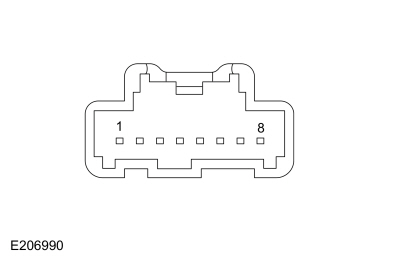 C541, pin 5, Component Side
|

|
 C541, pin 6, Component Side
|
-
While pressing and releasing the indicated memory recall button 2, measure the component side resistance of the driver door lock control switch using the following table:
|
Positive Lead
|
Measurement / Action
|
Negative Lead
|
 C541, pin 4, Component Side
|

|
 C541, pin 6, Component Side
|
Are the resistances less than 20 ohms with the
switch buttons pressed and greater than 10,000 ohms with the switch
buttons released?
| No |
INSTALL a new door lock control switch.
REFER to: Door Lock Control Switch (501-14 Handles, Locks, Latches and Entry Systems, Removal and Installation).
|
|
| G5 CHECK THE MEMORY SET SWITCH GROUND CIRCUIT FOR AN OPEN |
-
Measure:
Click to display connectors
|
Positive Lead
|
Measurement / Action
|
Negative Lead
|
|
C541-6
|

|
Ground
|
Is the resistance less than 3 ohms?
|
| G6 CHECK THE MEMORY SET CIRCUITS FOR A SHORT TO VOLTAGE |
-
Measure:
Click to display connectors
|
Positive Lead
|
Measurement / Action
|
Negative Lead
|
|
C541-4
|

|
Ground
|
|
C541-5
|

|
Ground
|
Is any voltage present?
| Yes |
REPAIR the affected circuit.
|
|
| G7 CHECK THE MEMORY SET SWITCH CIRCUITS FOR A SHORT TO GROUND |
-
Measure:
Click to display connectors
|
Positive Lead
|
Measurement / Action
|
Negative Lead
|
|
C541-4
|

|
Ground
|
|
C541-5
|

|
Ground
|
Is the resistance greater than 10,000 ohms?
| No |
REPAIR the affected circuit.
|
|
| G8 CHECK THE MEMORY SET SWITCH CIRCUITS FOR AN OPEN |
-
Measure:
Click to display connectors
|
Positive Lead
|
Measurement / Action
|
Negative Lead
|
|
C541-4
|

|
C501B-3
|
|
C541-5
|

|
C501B-1
|
Are the resistances less than 3 ohms?
| No |
REPAIR the affected circuit.
|
|
| G9 CHECK THE SEAT TRACK OPERATION USING DSM (DRIVER FRONT SEAT MODULE)
ACTIVE COMMANDS AND PARAMETER IDENTIFICATIONS (PIDS) |
-
Toggle the following DSM active commands ON and OFF using a diagnostic scan tool while monitoring the seat movement:
-
Front Motor Up (FRONT_UP)
-
Front Motor Down (FRONT_DWN)
-
Seat Height Motor Up (H_MOT_U)
-
Seat Height Motor Down (H_MOT_D)
-
Horizontal Motor Forward (HORZ_FWD)
-
Horizontal Motor Backward (HORZ_BWD)
-
Recline Motor Backward (RECL_BWD)
-
Recline Motor Forward (RECL_FWD)
Does the driver seat operate correctly?
| Yes |
The condition is intermittent. CHECK for causes of
an intermittent concern, particularly the pins and terminals of
electrical connectors that were disconnected. Do not install any new
components at this time. Components should only be installed when
directed to do so in the pinpoint test. REPAIR any intermittent wiring, terminal or connector concerns found.
|
| No |
DIAGNOSE the inoperative seat. GO to Pinpoint Test F
|
|
| G10 CHECK THE FRONT HEIGHT SENSOR CIRCUITS FOR A SHORT TO VOLTAGE |
-
 WARNING:
Turn the ignition OFF and wait one minute to
deplete the backup power supply. Failure to follow this instruction may
result in serious personal injury or death in the event of an accidental
deployment.
Ignition OFF.
WARNING:
Turn the ignition OFF and wait one minute to
deplete the backup power supply. Failure to follow this instruction may
result in serious personal injury or death in the event of an accidental
deployment.
Ignition OFF.
-
Disconnect: Driver Side Airbag In-line C3368.
-
Disconnect: DSM
C341A and C341F.
-
Disconnect: Driver Seat Front Height Motor C382.
-
Measure:
Click to display connectors
|
Positive Lead
|
Measurement / Action
|
Negative Lead
|
|
C382-2
|

|
Ground
|
|
C382-4
|

|
Ground
|
Is any voltage present?
| Yes |
REPAIR the affected circuit. GO to G23
|
|
| G11 CHECK THE FRONT HEIGHT SENSOR CIRCUITS FOR A SHORT TO GROUND |
-
Measure:
Click to display connectors
|
Positive Lead
|
Measurement / Action
|
Negative Lead
|
|
C382-2
|

|
Ground
|
|
C382-4
|

|
Ground
|
Are the resistances greater than 10,000 ohms?
| No |
REPAIR the affected circuit. GO to G23
|
|
| G12 CHECK THE FRONT HEIGHT SENSOR CIRCUITS FOR AN OPEN |
-
Measure:
Click to display connectors
|
Positive Lead
|
Measurement / Action
|
Negative Lead
|
|
C382-2
|

|
C341F-9
|
-
Measure:
Click to display connectors
|
Positive Lead
|
Measurement / Action
|
Negative Lead
|
|
C382-4
|

|
C341A-19
|
Are the resistances less than 3 ohms?
| Yes |
INSTALL a new driver seat track.
REFER to: Front Seat Track (501-10A Front Seats, Removal and Installation).
GO to G23
|
| No |
REPAIR the affected circuit. GO to G23
|
|
| G13 CHECK THE REAR HEIGHT SENSOR CIRCUITS FOR A SHORT TO VOLTAGE |
-
 WARNING:
Turn the ignition OFF and wait one minute to
deplete the backup power supply. Failure to follow this instruction may
result in serious personal injury or death in the event of an accidental
deployment.
Ignition OFF.
WARNING:
Turn the ignition OFF and wait one minute to
deplete the backup power supply. Failure to follow this instruction may
result in serious personal injury or death in the event of an accidental
deployment.
Ignition OFF.
-
Disconnect: Driver Side Airbag In-line C3368.
-
Disconnect: DSM
C341A and C341F.
-
Disconnect: Driver Seat Rear Height Motor C363.
-
Measure:
Click to display connectors
|
Positive Lead
|
Measurement / Action
|
Negative Lead
|
|
C363-2
|

|
Ground
|
|
C363-4
|

|
Ground
|
Is any voltage present on any circuits?
| Yes |
REPAIR the affected circuit. GO to G23
|
|
| G14 CHECK THE REAR HEIGHT SENSOR CIRCUITS FOR A SHORT TO GROUND |
-
Measure:
Click to display connectors
|
Positive Lead
|
Measurement / Action
|
Negative Lead
|
|
C363-2
|

|
Ground
|
|
C363-4
|

|
Ground
|
Are the resistances greater than 10,000 ohms?
| No |
REPAIR the affected circuit. GO to G23
|
|
| G15 CHECK THE REAR HEIGHT SENSOR CIRCUITS FOR AN OPEN |
-
Measure:
Click to display connectors
|
Positive Lead
|
Measurement / Action
|
Negative Lead
|
|
C363-2
|

|
C341A-18
|
-
Measure:
Click to display connectors
|
Positive Lead
|
Measurement / Action
|
Negative Lead
|
|
C363-4
|

|
C341F-9
|
Are the resistances less than 3 ohms?
| Yes |
INSTALL a new driver seat track.
REFER to: Front Seat Track (501-10A Front Seats, Removal and Installation).
GO to G23
|
| No |
REPAIR the affected circuit. GO to G23
|
|
| G16 CHECK THE HORIZONTAL SENSOR CIRCUITS FOR A SHORT TO VOLTAGE |
-
 WARNING:
Turn the ignition OFF and wait one minute to
deplete the backup power supply. Failure to follow this instruction may
result in serious personal injury or death in the event of an accidental
deployment.
Ignition OFF.
WARNING:
Turn the ignition OFF and wait one minute to
deplete the backup power supply. Failure to follow this instruction may
result in serious personal injury or death in the event of an accidental
deployment.
Ignition OFF.
-
Disconnect: Driver Side Airbag In-line C3368.
-
Disconnect: DSM
C341A and C341F.
-
Disconnect: Driver Seat Horizontal Motor C362.
-
Measure:
Click to display connectors
|
Positive Lead
|
Measurement / Action
|
Negative Lead
|
|
C362-2
|

|
Ground
|
|
C362-4
|

|
Ground
|
Is any voltage present on any circuits?
| Yes |
REPAIR the affected circuit. GO to G23
|
|
| G17 CHECK THE HORIZONTAL SENSOR CIRCUITS FOR A SHORT TO GROUND |
-
Measure:
Click to display connectors
|
Positive Lead
|
Measurement / Action
|
Negative Lead
|
|
C362-2
|

|
Ground
|
|
C362-4
|

|
Ground
|
Are the resistances greater than 10,000 ohms?
| No |
REPAIR the affected circuit. GO to G23
|
|
| G18 CHECK THE HORIZONTAL SENSOR CIRCUITS FOR AN OPEN |
-
Measure:
Click to display connectors
|
Positive Lead
|
Measurement / Action
|
Negative Lead
|
|
C362-2
|

|
C341F-9
|
-
Measure:
Click to display connectors
|
Positive Lead
|
Measurement / Action
|
Negative Lead
|
|
C362-4
|

|
C341A-20
|
Are the resistances less than 3 ohms?
| Yes |
INSTALL a new horizontal motor.
REFER to: Front Seat Track Motor (501-10A Front Seats, Removal and Installation).
GO to G23
|
| No |
REPAIR the affected circuit. GO to G23
|
|
| G19 CHECK THE RECLINER SENSOR CIRCUITS FOR A SHORT TO VOLTAGE |
-
 WARNING:
Turn the ignition OFF and wait one minute to
deplete the backup power supply. Failure to follow this instruction may
result in serious personal injury or death in the event of an accidental
deployment.
Ignition OFF.
WARNING:
Turn the ignition OFF and wait one minute to
deplete the backup power supply. Failure to follow this instruction may
result in serious personal injury or death in the event of an accidental
deployment.
Ignition OFF.
-
Disconnect: Driver Side Airbag In-line C3368.
-
Disconnect: DSM
C341A and C341F.
-
Disconnect: Driver Seat Recliner Motor C3187.
-
Measure:
Click to display connectors
|
Positive Lead
|
Measurement / Action
|
Negative Lead
|
|
C3187-2
|

|
Ground
|
|
C3187-4
|

|
Ground
|
Is any voltage present?
| Yes |
REPAIR the affected circuit. GO to G23
|
|
| G20 CHECK THE RECLINER SENSOR CIRCUITS FOR A SHORT TO GROUND |
-
Measure:
Click to display connectors
|
Positive Lead
|
Measurement / Action
|
Negative Lead
|
|
C3187-2
|

|
Ground
|
|
C3187-4
|

|
Ground
|
Are the resistances greater than 10,000 ohms?
| No |
REPAIR the affected circuit. GO to G23
|
|
| G21 CHECK THE RECLINER SENSOR CIRCUITS FOR AN OPEN |
-
Measure:
Click to display connectors
|
Positive Lead
|
Measurement / Action
|
Negative Lead
|
|
C3187-2
|

|
C341A-17
|
-
Measure:
Click to display connectors
|
Positive Lead
|
Measurement / Action
|
Negative Lead
|
|
C3187-4
|

|
C341F-9
|
Are the resistances less than 3 ohms?
| Yes |
INSTALL a new driver seat backrest frame.
REFER to: Front Seat Backrest (501-10A Front Seats, Removal and Installation).
GO to G23
|
| No |
REPAIR the affected circuit. GO to G23
|
|
| G22 CHECK THE DDM (DRIVER DOOR MODULE)
OPERATION |
-
Disconnect and inspect all of the DDM connectors.
-
Repair:
-
corrosion (install new connector or terminals - clean module pins)
-
damaged or bent pins - install new terminals/pins as necessary
-
pushed-out pins - install new pins as necessary
-
Reconnect the DDM connectors. Make sure they seat and latch correctly.
-
Operate the system and determine if the concern is still present.
Is the concern still present?
| Yes |
CHECK OASIS for any applicable Technical Service Bulletins (TSBs). If a TSB exists for this concern, DISCONTINUE this test and FOLLOW TSB instructions. If no Technical Service Bulletins (TSBs) address this concern, INSTALL a new DDM.
REFER to: Driver Door Module (DDM) (419-10 Multifunction Electronic Modules, Removal and Installation).
|
| No |
The system is operating correctly at this time. The
concern may have been caused by module connections. ADDRESS the root
cause of any connector or pin issues.
|
|
| G23 CHECK FOR SRS (SUPPLEMENTAL RESTRAINT SYSTEM)
DIAGNOSTIC TROUBLE CODES (DTCS) |
-
 WARNING:
Turn the ignition OFF and wait one minute to
deplete the backup power supply. Failure to follow this instruction may
result in serious personal injury or death in the event of an accidental
deployment.
Ignition OFF.
WARNING:
Turn the ignition OFF and wait one minute to
deplete the backup power supply. Failure to follow this instruction may
result in serious personal injury or death in the event of an accidental
deployment.
Ignition OFF.
-
Connect: Passenger Side Airbag In-line C3206.
-
Connect all previously disconnected connectors.
-
Using a diagnostic scan tool, clear the RCM Diagnostic Trouble Codes (DTCs).
-
Cycle the ignition OFF then ON.
-
Using a diagnostic scan tool, perform RCM self-test.
Are any RCM Diagnostic Trouble Codes (DTCs) retrieved during self-test?
| Yes |
REFER to: Airbag Supplemental Restraint System (SRS) (501-20B Supplemental Restraint System, Diagnosis and Testing).
|
| No |
Repair is complete. RETURN the vehicle to the customer.
|
|
Easy Entry/Easy Exit is Inoperative/Does Not Operate Correctly
Normal Operation and Fault Conditions
REFER to: Front Seats - System Operation and Component Description (501-10A Front Seats, Description and Operation).
Possible Causes
-
Easy entry/exit feature is not enabled
-
Missing ignition status information
-
DSM
Visual Inspection and Diagnostic Pre-checks
-
Verify the easy entry/exit feature is enabled in the
message center. REFER to the Owner's Literature for information on
programming vehicle settings in the message center.
PINPOINT TEST H : EASY ENTRY/EASY EXIT IS INOPERATIVE/DOES NOT OPERATE CORRECTLY
| H1 CHECK THE DRIVER POWER SEAT OPERATION |
-
Check the message center to verify the easy entry/exit feature is turned on.
-
Using the seat control switch, verify the driver power seat operates fully forward and backward.
-
Using a diagnostic scan tool, perform the DSM self-test.
Are any Diagnostic Trouble Codes (DTCs) received?
| Yes |
REFER to the DSM
DTC Chart.
|
| No |
If disabled, ENABLE the easy entry/exit feature
through the message center. REFER to the Owner's Literature. TEST the
system for normal operation. If OK, INSTRUCT the customer on correct
system operation. GO to H2
|
|
| H2 CHECK THE DSM (DRIVER FRONT SEAT MODULE)
IGNITION POSITION FINAL STATUS PID (PARAMETER IDENTIFICATION)
STATES |
-
Using a diagnostic scan tool, monitor the DSM IGN_FINAL PID while cycling the ignition from ON to OFF and back to ON.
Does the PID states match with ignition mode?
| Yes |
INSTALL a new DSM.
REFER to: Driver Front Seat Module (DSM) (501-10A Front Seats, Removal and Installation).
|
| No |
DIAGNOSE the ignition status concern.
REFER to: Steering Wheel and Column Electrical Components (211-05 Steering Wheel and Column Electrical Components, Diagnosis and Testing).
|
|
The Heated Seats are Inoperative — Driver and Passenger
Refer to Wiring Diagrams Cell 119 for schematic and connector information.
Normal Operation and Fault Conditions
REFER to: Front Seats - System Operation and Component Description (501-10A Front Seats, Description and Operation).
Possible Causes
-
Fuse
-
Wiring, terminals or connectors
-
FCIM
-
FDIM (if equipped)
Visual Inspection and Diagnostic Pre-checks
-
Verify the BJB fuse 65 (20A)
PINPOINT TEST I : THE HEATED SEATS ARE INOPERATIVE — DRIVER AND PASSENGER
 WARNING:
Incorrect repair techniques or actions can cause an
accidental Supplemental Restraint System (SRS) deployment. Never
compromise or depart from these instructions. Failure to precisely
follow all instructions could result in serious personal injury from an
accidental deployment.
WARNING:
Incorrect repair techniques or actions can cause an
accidental Supplemental Restraint System (SRS) deployment. Never
compromise or depart from these instructions. Failure to precisely
follow all instructions could result in serious personal injury from an
accidental deployment.
|
| I1 CHECK FOR FCIM (FRONT CONTROLS INTERFACE MODULE)
DIAGNOSTIC TROUBLE CODES (DTCS) |
-
Using a diagnostic scan tool, perform FCIM self-test.
Are any FCIM Diagnostic Trouble Codes (DTCs) present?
| Yes |
REFER to the FCIM
DTC Chart.
|
| No |
If equipped with heated seat buttons on a touchscreen, GO to I2
If not equipped with heated seat buttons on a touchscreen, GO to I3
|
|
| I2 CHECK THE TOUCHSCREEN OPERATION |
-
Select each audio and climate control function using the touchscreen controls.
Do all touchscreen controls operate?
| No |
DIAGNOSE the inoperative touchscreen, Refer to the appropriate section in Group 415 for the procedure.
|
|
| I3 CHECK THE HEATED SEAT VOLTAGE SUPPLY CIRCUIT FOR AN OPEN |
-
Measure:
Click to display connectors
|
Positive Lead
|
Measurement / Action
|
Negative Lead
|
|
C2402B-1
|

|
Ground
|
Is the voltage greater than 11 volts?
| No |
VERIFY BJB
fuse 65 (20A) is OK. If OK, REPAIR the circuit. If not OK, REFER to the
Wiring Diagrams manual to identify the possible causes of the circuit
short.
|
|
| I4 CHECK THE HEATED SEAT TEMPERATURE SENSOR RETURN CIRCUIT FOR AN OPEN OR SHORT TO GROUND |
-
 WARNING:
Turn the ignition OFF and wait one minute to
deplete the backup power supply. Failure to follow this instruction may
result in serious personal injury or death in the event of an accidental
deployment.
Ignition OFF.
WARNING:
Turn the ignition OFF and wait one minute to
deplete the backup power supply. Failure to follow this instruction may
result in serious personal injury or death in the event of an accidental
deployment.
Ignition OFF.
-
Disconnect: Driver Side Airbag In-line C3368.
-
Disconnect: Left Front Seat Cushion Heater C3298.
-
Measure:
Click to display connectors
|
Positive Lead
|
Measurement / Action
|
Negative Lead
|
|
C3298-3
|

|
Ground
|
-
Measure:
Click to display connectors
|
Positive Lead
|
Measurement / Action
|
Negative Lead
|
|
C3298-3
|

|
C2402A-2
|
Is the resistance greater than 10,000 ohms between
the driver seat cushion heater mat and ground; and less than 3 ohms
between the driver seat cushion heater mat and the FCIM?
| No |
REPAIR the circuit. GO to I6
|
|
| I5 CHECK THE FCIM (FRONT CONTROLS INTERFACE MODULE)
OPERATION |
-
Disconnect and inspect all of the FCIM connectors.
-
Repair:
-
corrosion (install new connector or terminals - clean module pins)
-
damaged or bent pins - install new terminals/pins as necessary
-
pushed-out pins - install new pins as necessary
-
Reconnect the FCIM connectors. Make sure they seat and latch correctly.
-
NOTE:
Do not reconnect Driver Side Airbag In-line C3368 at this time.
Reconnect all previously disconnected connectors.
-
Operate the system and determine if the concern is still present.
Is the concern still present?
| Yes |
CHECK OASIS for any applicable Technical Service Bulletins (TSBs). If a TSB exists for this concern, DISCONTINUE this test and FOLLOW TSB instructions. If no Technical Service Bulletins (TSBs) address this concern,
 Click here to access Guided Routine (FCIM).
 Internet Explorer version 11 or greater is required to perform this Pinpoint Test. Internet Explorer version 11 or greater is required to perform this Pinpoint Test.
GO to I6
|
| No |
The system is operating correctly at this time. The
concern may have been caused by module connections. ADDRESS the root
cause of any connector or pin issues. GO to I6
|
|
| I6 CHECK FOR SRS (SUPPLEMENTAL RESTRAINT SYSTEM)
DIAGNOSTIC TROUBLE CODES (DTCS) |
-
 WARNING:
Turn the ignition OFF and wait one minute to
deplete the backup power supply. Failure to follow this instruction may
result in serious personal injury or death in the event of an accidental
deployment.
Ignition OFF.
WARNING:
Turn the ignition OFF and wait one minute to
deplete the backup power supply. Failure to follow this instruction may
result in serious personal injury or death in the event of an accidental
deployment.
Ignition OFF.
-
Connect: Driver Side Airbag In-line C3368.
-
Connect all previously disconnected connectors (if not previously re-connected).
-
Using a diagnostic scan tool, clear the RCM Diagnostic Trouble Codes (DTCs).
-
Cycle the ignition OFF then ON.
-
Using a diagnostic scan tool, perform RCM self-test.
Are any RCM Diagnostic Trouble Codes (DTCs) retrieved during self-test?
| Yes |
REFER to: Airbag Supplemental Restraint System (SRS) (501-20B Supplemental Restraint System, Diagnosis and Testing).
|
| No |
Repair is complete. RETURN the vehicle to the customer.
|
|
The Heated Seat is Inoperative/Does Not Operate Correctly — Driver
Refer to Wiring Diagrams Cell 119 for schematic and connector information.
Normal Operation and Fault Conditions
REFER to: Front Seats - System Operation and Component Description (501-10A Front Seats, Description and Operation).
DTC Fault Trigger Conditions
|
DTC
|
Description
|
Fault Trigger Conditions
|
|
B1034:11
|
Left Front Seat Heater Element: Circuit Short To Ground
|
Sets when the FCIM senses the left front heater element current draw has exceeded a specified threshold. When this DTC sets, the FCIM disables the circuit until the ignition is cycled.
|
|
B1034:12
|
Left Front Seat Heater Element: Circuit Short To Battery
|
Sets when the FCIM senses the left front heater circuit voltage is above a specified threshold when the driver is active. When this DTC sets, the FCIM disables the circuit until the ignition is cycled.
|
|
B1034:13
|
Left Front Seat Heater Element: Circuit Open
|
Sets when the FCIM senses the left front heater element current draw is less than a specified threshold. When this DTC sets, the FCIM disables the circuit until the ignition is cycled.
|
|
B1038:11
|
Left Front Seat Heater Sensor: Circuit Short To Ground
|
Sets when the FCIM senses the left front heater sensor voltage is out-of-range low. When this DTC sets, the FCIM disables the circuit until the ignition is cycled.
|
|
B1038:15
|
Left Front Seat Heater Sensor: Circuit Short To Battery or Open
|
Sets when the FCIM senses the left front heater sensor voltage is out-of-range high. When this DTC sets, the FCIM disables the circuit until the ignition is cycled.
|
Possible Causes
-
Wiring, terminals or connectors
-
Heater mat
-
FCIM
PINPOINT TEST J : THE HEATED SEAT IS INOPERATIVE/DOES NOT OPERATE CORRECTLY — DRIVER
 WARNING:
Incorrect repair techniques or actions can cause an
accidental Supplemental Restraint System (SRS) deployment. Never
compromise or depart from these instructions. Failure to precisely
follow all instructions could result in serious personal injury from an
accidental deployment.
WARNING:
Incorrect repair techniques or actions can cause an
accidental Supplemental Restraint System (SRS) deployment. Never
compromise or depart from these instructions. Failure to precisely
follow all instructions could result in serious personal injury from an
accidental deployment.
|
| J1 CHECK FOR FCIM (FRONT CONTROLS INTERFACE MODULE)
DIAGNOSTIC TROUBLE CODES (DTCS) |
-
Using a diagnostic scan tool, perform FCIM self-test.
Are any FCIM Diagnostic Trouble Codes (DTCs) present?
| Yes |
For DTC B1034:11, B1034:12 or B1034:13, GO to J3
For DTC B1038:11 or B1038:15, GO to J5
For all other Diagnostic Trouble Codes (DTCs), Refer
to the appropriate section in Group 415 for the procedure.
|
| No |
If equipped with a touchscreen, GO to J2
If not equipped with a touchscreen, GO to J3
|
|
| J2 CHECK THE TOUCHSCREEN OPERATION |
-
Select each audio and climate control function using the touchscreen controls.
Do all touchscreen controls operate?
| No |
DIAGNOSE the inoperative touchscreen, Refer to the appropriate section
in Group 415 for the procedure.
|
|
| J3 CHECK THE HEATED SEAT VOLTAGE SUPPLY CIRCUIT FOR AN OPEN |
-
Measure:
Click to display connectors
|
Positive Lead
|
Measurement / Action
|
Negative Lead
|
|
C2402B-1
|

|
Ground
|
Is the voltage greater than 11 volts?
|
| J4 CHECK THE HEATER ELEMENT POWER CIRCUIT FOR AN OPEN OR SHORT TO GROUND |
-
 WARNING:
Turn the ignition OFF and wait one minute to
deplete the backup power supply. Failure to follow this instruction may
result in serious personal injury or death in the event of an accidental
deployment.
Ignition OFF.
WARNING:
Turn the ignition OFF and wait one minute to
deplete the backup power supply. Failure to follow this instruction may
result in serious personal injury or death in the event of an accidental
deployment.
Ignition OFF.
-
Disconnect: Driver Side Airbag In-line C3368.
-
Disconnect: FCIM
C2402B (if not previously disconnected).
-
Disconnect: Left Front Seat Cushion Heater C3298.
-
Measure:
Click to display connectors
|
Positive Lead
|
Measurement / Action
|
Negative Lead
|
|
C3298-1
|

|
Ground
|
-
Measure:
Click to display connectors
|
Positive Lead
|
Measurement / Action
|
Negative Lead
|
|
C3298-1
|

|
C2402B-16
|
Is the resistance greater than 10,000 ohms between
the driver seat cushion heater mat and ground; and less than 3 ohms
between the driver seat cushion heater mat and the FCIM?
| No |
REPAIR the circuit. GO to J14
|
|
| J5 CHECK THE HEATED SEAT TEMPERATURE SENSOR CIRCUIT FOR AN OPEN OR SHORT TO GROUND |
-
 WARNING:
Turn the ignition OFF and wait one minute to
deplete the backup power supply. Failure to follow this instruction may
result in serious personal injury or death in the event of an accidental
deployment.
Ignition OFF.
WARNING:
Turn the ignition OFF and wait one minute to
deplete the backup power supply. Failure to follow this instruction may
result in serious personal injury or death in the event of an accidental
deployment.
Ignition OFF.
-
Disconnect: Driver Side Airbag In-line C3368.
-
Disconnect: Left Front Seat Cushion Heater C3298.
-
Measure:
Click to display connectors
|
Positive Lead
|
Measurement / Action
|
Negative Lead
|
|
C3298-2
|

|
Ground
|
-
Measure:
Click to display connectors
|
Positive Lead
|
Measurement / Action
|
Negative Lead
|
|
C3298-2
|

|
C2402B-30
|
Is the resistance greater than 10,000 ohms between
the driver seat cushion heater mat and ground; and less than 3 ohms
between the driver seat cushion heater mat and the FCIM?
| No |
REPAIR the circuit. GO to J14
|
|
| J6 CHECK THE HEATED SEAT TEMPERATURE SENSOR RETURN CIRCUIT FOR AN OPEN OR SHORT TO GROUND |
-
Measure:
Click to display connectors
|
Positive Lead
|
Measurement / Action
|
Negative Lead
|
|
C3298-3
|

|
Ground
|
-
Measure:
Click to display connectors
|
Positive Lead
|
Measurement / Action
|
Negative Lead
|
|
C3298-3
|

|
C2402A-2
|
Is the resistance greater than 10,000 ohms between
the driver seat cushion heater mat and ground; and less than 3 ohms
between the driver seat cushion heater mat and the FCIM?
| No |
REPAIR the circuit. GO to J14
|
|
| J7 CHECK THE HEATED SEAT TEMPERATURE SENSOR CIRCUIT FOR A SHORT TO VOLTAGE |
-
Measure:
Click to display connectors
|
Positive Lead
|
Measurement / Action
|
Negative Lead
|
|
C3298-2
|

|
Ground
|
Is any voltage present?
| Yes |
REPAIR the circuit. GO to J14
|
|
| J8 CHECK THE HEATER ELEMENT GROUND CIRCUIT FOR AN OPEN |
-
Disconnect: Left Front Seat Backrest Heater C365.
-
Measure:
Click to display connectors
|
Positive Lead
|
Measurement / Action
|
Negative Lead
|
|
C365-2
|

|
Ground
|
Is the resistance less than 0.5 ohms?
| No |
REPAIR the circuit. GO to J14
|
|
| J9 CHECK CUSHION HEATED SEAT MAT FOR AN OPEN OR SHORT TO GROUND |
-
Measure the component side resistance between:
|
Positive Lead
|
Measurement / Action
|
Negative Lead
|
 C3298-1, Component Side
|

|
Ground
|
-
Measure the component side resistance between:
|
Positive Lead
|
Measurement / Action
|
Negative Lead
|
 C3298-1, Component Side
|

|
 C3298-4, Component Side
|
Is the resistance between 0.6 and 2 ohms between
pins 1 and 4; and greater than 10,000 ohms between pin 1 and ground?
| No |
INSTALL a new driver seat cushion heater mat.
REFER to: Seat Heater Mat Removal (501-10A Front Seats, General Procedures).
GO to J14
|
|
| J10 CHECK THE BACKREST HEATED SEAT MAT FOR AN OPEN OR SHORT TO GROUND |
-
Measure the component side resistance between:
|
Positive Lead
|
Measurement / Action
|
Negative Lead
|
 C365-1, Component Side
|

|
 C365-2, Component Side
|
Is the resistance between 0.6 and 2 ohms between
pins 1 and 2; and greater than 10,000 ohms between pin 2 and ground?
| No |
INSTALL a new driver seat backrest heater mat.
REFER to: Seat Heater Mat Removal (501-10A Front Seats, General Procedures).
GO to J14
|
|
| J11 CHECK THE CIRCUIT BETWEEN THE CUSHION HEATER MAT AND BACKREST HEATER MAT FOR AN OPEN AND SHORT TO GROUND |
-
Measure:
Click to display connectors
|
Positive Lead
|
Measurement / Action
|
Negative Lead
|
|
C3298-4
|

|
Ground
|
-
Measure:
Click to display connectors
|
Positive Lead
|
Measurement / Action
|
Negative Lead
|
|
C3298-4
|

|
C365-1
|
Is the resistance greater than 10,000 ohms between
the driver seat cushion heater mat and ground; and less than 3 ohms
between the driver seat cushion heater mat and the backrest heater mat?
| No |
REPAIR the circuit. GO to J14
|
|
| J12 CHECK THE HEATED SEAT TEMPERATURE SENSOR FOR AN OPEN OR SHORT TO GROUND |
-
Measure the component side resistance between:
|
Positive Lead
|
Measurement / Action
|
Negative Lead
|
 C3298-2, Component Side
|

|
Ground
|
-
Measure the component side resistance between:
|
Positive Lead
|
Measurement / Action
|
Negative Lead
|
 C3298-2, Component Side
|

|
 C3298-3, Component Side
|
Is the resistance between 300 ohms and 300,000 ohms
between pins 2 and 3; and greater than 10,000 ohms between pin 2 and
ground?
| No |
INSTALL a new driver seat cushion heater mat.
REFER to: Seat Heater Mat Removal (501-10A Front Seats, General Procedures).
GO to J14
|
|
| J13 CHECK THE FCIM (FRONT CONTROLS INTERFACE MODULE)
OPERATION |
-
Disconnect and inspect all of the FCIM connectors.
-
Repair:
-
corrosion (install new connector or terminals - clean module pins)
-
damaged or bent pins - install new terminals/pins as necessary
-
pushed-out pins - install new pins as necessary
-
Reconnect the FCIM connectors. Make sure they seat and latch correctly.
-
Reconnect all previously disconnected connectors.
-
Operate the system and determine if the concern is still present.
Is the concern still present?
| Yes |
CHECK OASIS for any applicable Technical Service Bulletins (TSBs). If a TSB exists for this concern, DISCONTINUE this test and FOLLOW TSB instructions. If no Technical Service Bulletins (TSBs) address this concern,
 Click here to access Guided Routine (FCIM).
 Internet Explorer version 11 or greater is required to perform this Pinpoint Test. Internet Explorer version 11 or greater is required to perform this Pinpoint Test.
GO to J14
|
| No |
The system is operating correctly at this time. The
concern may have been caused by module connections. ADDRESS the root
cause of any connector or pin issues. GO to J14
|
|
| J14 CHECK FOR SRS (SUPPLEMENTAL RESTRAINT SYSTEM)
DIAGNOSTIC TROUBLE CODES (DTCS) |
-
 WARNING:
Turn the ignition OFF and wait one minute to
deplete the backup power supply. Failure to follow this instruction may
result in serious personal injury or death in the event of an accidental
deployment.
Ignition OFF.
WARNING:
Turn the ignition OFF and wait one minute to
deplete the backup power supply. Failure to follow this instruction may
result in serious personal injury or death in the event of an accidental
deployment.
Ignition OFF.
-
Connect: Driver Side Airbag In-line C3368.
-
Connect all previously disconnected connectors (if not previously re-connected).
-
Using a diagnostic scan tool, clear the RCM Diagnostic Trouble Codes (DTCs).
-
Cycle the ignition OFF then ON.
-
Using a diagnostic scan tool, perform RCM self-test.
Are any RCM Diagnostic Trouble Codes (DTCs) retrieved during self-test?
| Yes |
REFER to: Airbag Supplemental Restraint System (SRS) (501-20B Supplemental Restraint System, Diagnosis and Testing).
|
| No |
Repair is complete. RETURN the vehicle to the customer.
|
|
The Heated Seat is Inoperative/Does Not Operate Correctly — Passenger
Refer to Wiring Diagrams Cell 119 for schematic and connector information.
Normal Operation and Fault Conditions
REFER to: Front Seats - System Operation and Component Description (501-10A Front Seats, Description and Operation).
DTC Fault Trigger Conditions
|
DTC
|
Description
|
Fault Trigger Conditions
|
|
B1036:11
|
Right Front Seat Heater Element: Circuit Short To Ground
|
Sets when the FCIM senses the right front heater element current draw has exceeded a specified threshold. When this DTC sets, the FCIM disables the circuit until the ignition is cycled.
|
|
B1036:12
|
Right Front Seat Heater Element: Circuit Short To Battery
|
Sets when the FCIM senses the right front heater circuit voltage is above a specified threshold when the driver is active. When this DTC sets, the FCIM disables the circuit until the ignition is cycled.
|
|
B1036:13
|
Right Front Seat Heater Element: Circuit Open
|
Sets when the FCIM senses the right front heater element current draw is less than a specified threshold. When this DTC sets, the FCIM disables the circuit until the ignition is cycled.
|
|
B103A:11
|
Right Front Seat Heater Sensor: Circuit Short To Ground
|
Sets when the FCIM senses the right front heater sensor voltage is out-of-range low. When this DTC sets, the FCIM disables the circuit until the ignition is cycled.
|
|
B103A:15
|
Right Front Seat Heater Sensor: Circuit Short To Battery or Open
|
Sets when the FCIM senses the right front heater sensor voltage is out-of-range high. When this DTC sets, the FCIM disables the circuit until the ignition is cycled.
|
Possible Causes
-
Wiring, terminals or connectors
-
Heater mat
-
FCIM
PINPOINT TEST K : THE HEATED SEAT IS INOPERATIVE/DOES NOT OPERATE CORRECTLY — PASSENGER
 WARNING:
Incorrect repair techniques or actions can cause an
accidental Supplemental Restraint System (SRS) deployment. Never
compromise or depart from these instructions. Failure to precisely
follow all instructions could result in serious personal injury from an
accidental deployment.
WARNING:
Incorrect repair techniques or actions can cause an
accidental Supplemental Restraint System (SRS) deployment. Never
compromise or depart from these instructions. Failure to precisely
follow all instructions could result in serious personal injury from an
accidental deployment.
|
| K1 CHECK FOR FCIM (FRONT CONTROLS INTERFACE MODULE)
DIAGNOSTIC TROUBLE CODES (DTCS) |
-
Using a diagnostic scan tool, perform FCIM self-test.
Are any FCIM Diagnostic Trouble Codes (DTCs) present?
| Yes |
For DTC B1036:11, B1036:12 or B1036:13, GO to K3
For DTC B103A:11 or B103A:15, GO to K5
For all other Diagnostic Trouble Codes (DTCs), Refer
to the appropriate section in Group 415 for the procedure.
|
| No |
If equipped with heated seat buttons on a touchscreen, GO to K2
If not equipped with heated seat buttons on a touchscreen, GO to K3
|
|
| K2 CHECK THE TOUCHSCREEN OPERATION |
-
Select each audio and climate control function using the touchscreen controls.
Do all touchscreen controls operate?
| No |
DIAGNOSE the inoperative touchscreen, Refer to the appropriate section
in Group 415 for the procedure.
|
|
| K3 CHECK THE HEATED SEAT VOLTAGE SUPPLY CIRCUIT FOR AN OPEN |
-
Measure:
Click to display connectors
|
Positive Lead
|
Measurement / Action
|
Negative Lead
|
|
C2402B-2
|

|
Ground
|
Is the voltage greater than 11 volts?
|
| K4 CHECK THE HEATER ELEMENT POWER CIRCUIT FOR AN OPEN OR SHORT TO GROUND |
-
 WARNING:
Turn the ignition OFF and wait one minute to
deplete the backup power supply. Failure to follow this instruction may
result in serious personal injury or death in the event of an accidental
deployment.
Ignition OFF.
WARNING:
Turn the ignition OFF and wait one minute to
deplete the backup power supply. Failure to follow this instruction may
result in serious personal injury or death in the event of an accidental
deployment.
Ignition OFF.
-
Disconnect: Passenger Side Airbag In-line C3206.
-
Disconnect: FCIM
C2402B (if not previously disconnected).
-
Disconnect: Right Front Seat Cushion Heater C334.
-
Measure:
Click to display connectors
|
Positive Lead
|
Measurement / Action
|
Negative Lead
|
|
C334-1
|

|
Ground
|
-
Measure:
Click to display connectors
|
Positive Lead
|
Measurement / Action
|
Negative Lead
|
|
C334-1
|

|
C2402B-17
|
Is the resistance greater than 10,000 ohms between
the passenger seat cushion heater mat and ground; and less than 3 ohms
between the passenger seat cushion heater mat and the FCIM?
| No |
REPAIR the circuit. GO to K14
|
|
| K5 CHECK THE HEATED SEAT TEMPERATURE SENSOR CIRCUIT FOR AN OPEN OR SHORT TO GROUND |
-
 WARNING:
Turn the ignition OFF and wait one minute to
deplete the backup power supply. Failure to follow this instruction may
result in serious personal injury or death in the event of an accidental
deployment.
Ignition OFF.
WARNING:
Turn the ignition OFF and wait one minute to
deplete the backup power supply. Failure to follow this instruction may
result in serious personal injury or death in the event of an accidental
deployment.
Ignition OFF.
-
Disconnect: Passenger Side Airbag In-line C3206.
-
Disconnect: Right Front Seat Cushion Heater C334.
-
Measure:
Click to display connectors
|
Positive Lead
|
Measurement / Action
|
Negative Lead
|
|
C334-2
|

|
Ground
|
-
Measure:
Click to display connectors
|
Positive Lead
|
Measurement / Action
|
Negative Lead
|
|
C334-2
|

|
C2402B-15
|
Is the resistance greater than 10,000 ohms between
the passenger seat cushion heater mat and ground; and less than 3 ohms
between the passenger seat cushion heater mat and the FCIM?
| No |
REPAIR the circuit. GO to K14
|
|
| K6 CHECK THE HEATED SEAT TEMPERATURE SENSOR RETURN CIRCUIT FOR AN OPEN OR SHORT TO GROUND |
-
Measure:
Click to display connectors
|
Positive Lead
|
Measurement / Action
|
Negative Lead
|
|
C334-3
|

|
Ground
|
-
Measure:
Click to display connectors
|
Positive Lead
|
Measurement / Action
|
Negative Lead
|
|
C334-3
|

|
C2402A-2
|
Is the resistance greater than 10,000 ohms between
the passenger seat cushion heater mat and ground; and less than 3 ohms
between the passenger seat cushion heater mat and the FCIM?
| No |
REPAIR the circuit. GO to K14
|
|
| K7 CHECK THE HEATED SEAT TEMPERATURE SENSOR CIRCUIT FOR A SHORT TO VOLTAGE |
-
Measure:
Click to display connectors
|
Positive Lead
|
Measurement / Action
|
Negative Lead
|
|
C334-2
|

|
Ground
|
Is any voltage present?
| Yes |
REPAIR the circuit. GO to K14
|
|
| K8 CHECK THE HEATER ELEMENT GROUND CIRCUIT FOR AN OPEN |
-
Disconnect: Right Front Seat Backrest Heater C335.
-
Measure:
Click to display connectors
|
Positive Lead
|
Measurement / Action
|
Negative Lead
|
|
C335-2
|

|
Ground
|
Is the resistance less than 0.5 ohms?
| No |
REPAIR the circuit. GO to K14
|
|
| K9 CHECK CUSHION HEATED SEAT MAT FOR AN OPEN OR SHORT TO GROUND |
-
Measure the component side resistance between:
|
Positive Lead
|
Measurement / Action
|
Negative Lead
|
 C334-1, Component Side
|

|
Ground
|
-
Measure the component side resistance between:
|
Positive Lead
|
Measurement / Action
|
Negative Lead
|
 C334-1, Component Side
|

|
 C334-4, Component Side
|
Is the resistance between 0.6 and 2 ohms between
pins 1 and 4; and greater than 10,000 ohms between pin 1 and ground?
| No |
INSTALL a new passenger seat cushion heater mat.
REFER to: Seat Heater Mat Removal (501-10A Front Seats, General Procedures).
GO to K14
|
|
| K10 CHECK THE BACKREST HEATED SEAT MAT FOR AN OPEN OR SHORT TO GROUND |
-
Measure the component side resistance between:
|
Positive Lead
|
Measurement / Action
|
Negative Lead
|
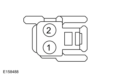 C335-1, Component Side
|

|
 C335-2, Component Side
|
Is the resistance between 0.6 and 2 ohms between
pins 1 and 2; and greater than 10,000 ohms between pin 2 and ground?
| No |
INSTALL a new passenger seat backrest heater mat.
REFER to: Seat Heater Mat Removal (501-10A Front Seats, General Procedures).
GO to K14
|
|
| K11 CHECK THE CIRCUIT BETWEEN THE CUSHION HEATER MAT AND BACKREST HEATER MAT FOR AN OPEN AND SHORT TO GROUND |
-
Measure:
Click to display connectors
|
Positive Lead
|
Measurement / Action
|
Negative Lead
|
|
C334-4
|

|
Ground
|
-
Measure:
Click to display connectors
|
Positive Lead
|
Measurement / Action
|
Negative Lead
|
|
C334-4
|

|
C335-1
|
Is the resistance greater than 10,000 ohms between
the passenger seat cushion heater mat and ground; and less than 3 ohms
between the passenger seat cushion heater mat and the backrest heater
mat?
| No |
REPAIR the circuit. GO to K14
|
|
| K12 CHECK THE HEATED SEAT TEMPERATURE SENSOR FOR AN OPEN OR SHORT TO GROUND |
-
Measure the component side resistance between:
|
Positive Lead
|
Measurement / Action
|
Negative Lead
|
 C334-2, Component Side
|

|
Ground
|
-
Measure the component side resistance between:
|
Positive Lead
|
Measurement / Action
|
Negative Lead
|
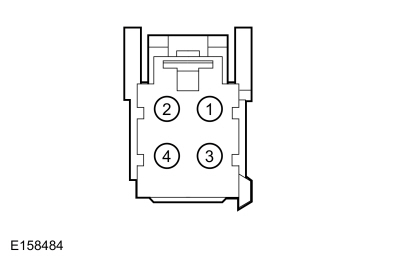 C334-2, Component Side
|

|
 C334-3, Component Side
|
Is the resistance between 300 ohms and 300,000 ohms
between pins 2 and 3; and greater than 10,000 ohms between pin 2 and
ground?
| No |
INSTALL a new passenger seat cushion heater mat.
REFER to: Seat Heater Mat Removal (501-10A Front Seats, General Procedures).
GO to K14
|
|
| K13 CHECK THE FCIM (FRONT CONTROLS INTERFACE MODULE)
OPERATION |
-
Disconnect and inspect all of the FCIM connectors.
-
Repair:
-
corrosion (install new connector or terminals - clean module pins)
-
damaged or bent pins - install new terminals/pins as necessary
-
pushed-out pins - install new pins as necessary
-
Reconnect the FCIM connectors. Make sure they seat and latch correctly.
-
Reconnect all previously disconnected connectors.
-
Operate the system and determine if the concern is still present.
Is the concern still present?
| Yes |
CHECK OASIS for any applicable Technical Service Bulletins (TSBs). If a TSB exists for this concern, DISCONTINUE this test and FOLLOW TSB instructions. If no Technical Service Bulletins (TSBs) address this concern,
 Click here to access Guided Routine (FCIM).
 Internet Explorer version 11 or greater is required to perform this Pinpoint Test. Internet Explorer version 11 or greater is required to perform this Pinpoint Test.
GO to K14
|
| No |
The system is operating correctly at this time. The
concern may have been caused by module connections. ADDRESS the root
cause of any connector or pin issues. GO to K14
|
|
| K14 CHECK FOR SRS (SUPPLEMENTAL RESTRAINT SYSTEM)
DIAGNOSTIC TROUBLE CODES (DTCS) |
-
 WARNING:
Turn the ignition OFF and wait one minute to
deplete the backup power supply. Failure to follow this instruction may
result in serious personal injury or death in the event of an accidental
deployment.
Ignition OFF.
WARNING:
Turn the ignition OFF and wait one minute to
deplete the backup power supply. Failure to follow this instruction may
result in serious personal injury or death in the event of an accidental
deployment.
Ignition OFF.
-
Connect: Passenger Side Airbag In-line C3206.
-
Connect all previously disconnected connectors (if not previously re-connected).
-
Using a diagnostic scan tool, clear the RCM Diagnostic Trouble Codes (DTCs).
-
Cycle the ignition OFF then ON.
-
Using a diagnostic scan tool, perform RCM self-test.
Are any RCM Diagnostic Trouble Codes (DTCs) retrieved during self-test?
| Yes |
REFER to: Airbag Supplemental Restraint System (SRS) (501-20B Supplemental Restraint System, Diagnosis and Testing).
|
| No |
Repair is complete. RETURN the vehicle to the customer.
|
|
DTC: U0140:00
Refer to Wiring Diagrams Cell 14 for schematic and connector information.
Normal Operation and Fault Conditions
The DSM and the BCM communicate using the MS-CAN.
DTC Fault Trigger Conditions
|
DTC
|
Description
|
Fault Trigger Conditions
|
|
U0140:00
|
Lost Communication with Body Control Module: No Sub Type Information
|
Set by the DSM whenever it has lost communication to the BCM for 5 seconds or longer while DSM input voltage is between 10 and 15.5 volts.
|
Possible Causes
-
Module communication
-
DSM
-
BCM
PINPOINT TEST L : DTC: U0140:00
| L1 VERIFY CUSTOMER CONCERN |
-
Verify there is an observable symptom present.
Is an observable symptom present?
| No |
The system is operating normally at this time. The DTC may have been set due to high network traffic or intermittent fault condition.
|
|
| L2 CHECK THE COMMUNICATION NETWORK |
-
Using a diagnostic scan tool, perform the network test.
Does the BCM pass the network test?
| No |
REFER to: Communications Network (418-00 Module Communications Network, Diagnosis and Testing).
|
|
| L3 RECHECK THE DSM (DRIVER FRONT SEAT MODULE)
DIAGNOSTIC TROUBLE CODES (DTCS) |
|
NOTE:
If new modules were installed prior to the DTC being set, the module configuration may be incorrectly set during PMI or the PMI may not have been carried out.
-
Using a diagnostic scan tool, clear the Continuous Memory Diagnostic Trouble Codes (CMDTCs).
-
Using a diagnostic scan tool, repeat the DSM self-test.
Is DTC U0140:00 still present?
| No |
The system is operating correctly at this time. The DTC may have been set due to high network traffic or intermittent fault condition.
|
|
| L4 CHECK FOR DTC U0140:00 IN OTHER MODULES |
|
NOTE:
If new modules were installed prior to the DTC being set, the module configuration may be incorrectly set during PMI or the PMI may not have been carried out.
-
Using a diagnostic scan tool, clear the Continuous Memory Diagnostic Trouble Codes (CMDTCs).
-
Using a diagnostic scan tool, retrieve the
Continuous Memory Diagnostic Trouble Codes (CMDTCs) from all modules.
Is DTC U0140:00 set in other modules?
| Yes |
 Click here to access Guided Routine (BCM).
 Internet Explorer version 11 or greater is required to perform this Pinpoint Test. Internet Explorer version 11 or greater is required to perform this Pinpoint Test.
|
| No |
INSTALL a new DSM.
REFER to: Driver Front Seat Module (DSM) (501-10A Front Seats, Removal and Installation).
|
|
One or Both Climate Controlled Seats are Inoperative
Refer to Wiring Diagrams Cell 119 for schematic and connector information.
Normal Operation and Fault Conditions
REFER to: Front Seats - System Operation and Component Description (501-10A Front Seats, Description and Operation).
Possible Causes
-
Wiring, terminals or connectors
-
FDIM
-
FCIM
-
DSM
Visual Inspection and Diagnostic Pre-checks
-
Verify BJB fuse 77 (30A) is OK.
PINPOINT TEST M : ONE OR BOTH CLIMATE CONTROLLED SEATS ARE INOPERATIVE
| M1 CHECK FOR SCME (FRONT SEAT CLIMATE CONTROL MODULE)
DIAGNOSTIC TROUBLE CODES (DTCS) |
-
Using a diagnostic scan tool, perform the SCME self-test.
Were any Diagnostic Trouble Codes (DTCs) retrieved?
| Yes |
GO to the SCME
DTC Chart.
|
| No |
If the diagnostic scan tool did not communicate to the SCME,
REFER to: Communications Network (418-00 Module Communications Network, Diagnosis and Testing).
Otherwise, GO to M2
|
|
| M2 CHECK OPERATION OF THE SCME (FRONT SEAT CLIMATE CONTROL MODULE)
USING PARAMETER IDENTIFICATIONS (PIDS) |
|
NOTE:
This step verifies the SCME is able to receive and process inbound command messages from the network and demonstrate if the SCME is operational. This indicates the FDIM or FCIM may not be sending the commands correctly.
-
Using a diagnostic scan tool, view the SCME Parameter Identifications (PIDs):
Driver Seat
-
Seat Cushion Temperature - Driver (SEAT_CSH_TMP_D)
-
Seat Back Temperature - Driver (SEAT_BK_TMP_D)
-
Left Seat Back Heating Control (HEAT_BACK_L)
-
Left Seat Cushion Heating Control (HEAT_CUSH_L)
Front Passenger Seat
-
Seat Cushion Temperature - Passenger (SEAT_CSH_TMP_P)
-
Seat Back Temperature - Passenger (SEAT_BK_TMP_P)
-
Right Seat Back Heating Control (HEAT_BACK_R)
-
Right Seat Cushion Heating Control (HEAT_CUSH_R)
-
NOTE:
The SCME active commands are limited to 15 seconds in the ON state.
Operate the affected climate controlled seat using
the active command while monitoring the appropriate Parameter
Identifications (PIDs) for that seat.
-
When the command is in process the blower motor
temperature Parameter Identifications (PIDs) on the affected seat should
momentarily increase. If no temperature increase is noted, verify the
cushion/backrest blower filter is unobstructed and repeat the active
command while physically monitoring the blower for fan movement.
Do the PID states or cushion/backrest blower movement indicate climate controlled seat operation when using the active command?
| No |
INSTALL a new DSM.
REFER to: Driver Front Seat Module (DSM) (501-10A Front Seats, Removal and Installation).
|
|
| M3 USE THE FCIM (FRONT CONTROLS INTERFACE MODULE)
BUTTONS AND MONITOR THE SCME (FRONT SEAT CLIMATE CONTROL MODULE)
PID (PARAMETER IDENTIFICATION)
FOR A RESPONSE |
-
Using a diagnostic scan tool, view the SCME Parameter Identifications (PIDs):
-
Climate Controlled Seat System State - Driver (CLIMATE_SEAT_D)
-
Climate Controlled Seat System State - Passenger (CLIMATE_SEAT_P)
-
NOTE:
Operation of the climate controlled seats
repeatedly on and off or repeatedly switching between heat and cool
modes may cause SCME
Diagnostic Trouble Codes (DTCs) to set, disabling one or both seat
systems and may require Diagnostic Trouble Codes (DTCs) to be cleared
before seat operation may continue. It is recommended to allow time
between modes for seat temperatures to return toward ambient
temperatures before continuing.
Attempt to operate the affected climate controlled seat in all modes using the appropriate buttons on the FCIM while monitoring the SCME
PID CLIMATE_SEAT_D or CLIMATE_SEAT_P.
Do all the PID states match the climate controlled seat settings selected on the FCIM?
| Yes |
To diagnose the inoperative touchscreen button(s),
Refer to the appropriate section in Group 415 for the procedure.
|
| No |
If only the climate seat functionality is inoperative,
 Click here to access Guided Routine (FCIM).
 Internet Explorer version 11 or greater is required to perform this Pinpoint Test. Internet Explorer version 11 or greater is required to perform this Pinpoint Test.
If other features of the FCIM are also inoperative, DIAGNOSE the FCIM concern. Refer to the appropriate section in Group 415 for the procedure.
|
|
DTC B1153:4B
Refer to Wiring Diagrams Cell 119 for schematic and connector information.
Normal Operation and Fault Conditions
REFER to: Front Seats - System Operation and Component Description (501-10A Front Seats, Description and Operation).
DTC Fault Trigger Conditions
|
DTC
|
Description
|
Fault Trigger Conditions
|
|
B1153:4B
|
Driver Seat Cushion: Over Temperature
|
If the driver seat cushion blower motor
temperature exceeds 110° C (230° F) in heat mode or 80° C (176° F) in
cool mode for more than 4 seconds the SCME shuts down the driver seat system and sets this DTC.
|
Possible Causes
-
Wiring, terminals or connectors
-
Restricted cushion blower motor filter
-
Crushed or restricted cushion foam pad
-
Cushion blower motor
-
DSM
PINPOINT TEST N : DTC B1153:4B
 WARNING:
Incorrect repair techniques or actions can cause an
accidental Supplemental Restraint System (SRS) deployment. Never
compromise or depart from these instructions. Failure to precisely
follow all instructions could result in serious personal injury from an
accidental deployment.
WARNING:
Incorrect repair techniques or actions can cause an
accidental Supplemental Restraint System (SRS) deployment. Never
compromise or depart from these instructions. Failure to precisely
follow all instructions could result in serious personal injury from an
accidental deployment.
|
| N1 CHECK THE SCME (FRONT SEAT CLIMATE CONTROL MODULE)
FOR ON-DEMAND DIAGNOSTIC TROUBLE CODES (DTCS) |
-
Start the vehicle and set the driver seat to HIGH heat.
-
Using a diagnostic scan tool, perform the SCME self-test.
Was DTC B1153:4B retrieved on-demand during the self-test?
|
| N2 CHECK THE DRIVER SEAT CUSHION BLOWER MOTOR THERMISTOR CIRCUITS FOR A SHORT TO GROUND |
-
 WARNING:
Turn the ignition OFF and wait one minute to
deplete the backup power supply. Failure to follow this instruction may
result in serious personal injury or death in the event of an accidental
deployment.
Ignition OFF.
WARNING:
Turn the ignition OFF and wait one minute to
deplete the backup power supply. Failure to follow this instruction may
result in serious personal injury or death in the event of an accidental
deployment.
Ignition OFF.
-
Disconnect: Driver Side Airbag In-line C3368.
-
Disconnect: Driver Cushion Blower Motor C3035.
-
Disconnect: Driver Backrest Blower Motor C3034.
-
Measure:
Click to display connectors
|
Positive Lead
|
Measurement / Action
|
Negative Lead
|
|
C341E-6
|

|
Ground
|
|
C341E-1
|

|
Ground
|
Are the resistances greater than 10,000 ohms?
| No |
REPAIR the affected circuit. GO to N22
|
|
| N3 CHECK THE DRIVER SEAT CUSHION BLOWER MOTOR THERMISTOR AND WIRING |
-
Connect: Driver Cushion Blower Motor C3035.
-
Connect: Driver Backrest Blower Motor C3034.
-
Measure:
Click to display connectors
|
Positive Lead
|
Measurement / Action
|
Negative Lead
|
|
C341E-6
|

|
C341E-1
|
-
Compare the measured resistance value with the following table:
|
Ambient Temperature
|
Resistance
|
|
0-10° C (32-50° F)
|
2,782-1,663 ohms
|
|
10-20° C (50-68° F)
|
1,837-1,140 ohms
|
|
20-30° C (68-86° F)
|
1,260-806 ohms
|
|
30-40° C (86-104° F)
|
893-570 ohms
|
|
40-50° C (104-122° F)
|
630-428 ohms
|
Is the resistance within the limits indicated?
|
| N4 CHECK THE DRIVER SEAT CUSHION BLOWER MOTOR THERMISTOR |
-
Disconnect: Driver Cushion Blower Motor C3035.
-
Measure the component side resistance between:
|
Positive Lead
|
Measurement / Action
|
Negative Lead
|
 C3035-5, Component Side
|

|
 C3035-8, Component Side
|
-
Compare the measured resistance value with the following table:
|
Ambient Temperature
|
Resistance
|
|
0-10° C (32-50° F)
|
2,782-1,663 ohms
|
|
10-20° C (50-68° F)
|
1,837-1,140 ohms
|
|
20-30° C (68-86° F)
|
1,260-806 ohms
|
|
30-40° C (86-104° F)
|
893-570 ohms
|
|
40-50° C (104-122° F)
|
630-428 ohms
|
Is the resistance within the limits indicated?
| Yes |
REPAIR circuit VHS26 (VT) or RHS05 (YE/VT) for an open or high resistance. GO to N22
|
| No |
INSTALL a new driver seat cushion blower motor.
REFER to: Front Seat Cushion Blower Motor (501-10A Front Seats, Removal and Installation).
GO to N22
|
|
| N5
CONFIRM THE FAULT WHILE MONITORING THE SCME (FRONT SEAT CLIMATE CONTROL
MODULE)
SEAT BACK TEMPERATURE - DRIVER (SEAT_BK_TMP_D) AND SEAT CUSHION
TEMPERATURE - DRIVER (SEAT_CSH_TMP_D) PARAMETER IDENTIFICATIONS (PIDS) |
-
Set the driver seat to OFF.
-
Using a diagnostic scan tool, clear the SCME Diagnostic Trouble Codes (DTCs).
-
Using a diagnostic scan tool, monitor the SCME SEAT_BK_TMP_D and SEAT_CSH_TMP_D.
-
NOTE:
A crushed seat cushion foam pad may be the cause
of the fault making it necessary to occupy the seat to recreate and
identify the fault.
Attempt to recreate the fault. Start the vehicle and
set the driver seat to HIGH heat for at least 15 minutes while
occupying the seat.
Do the Parameter Identifications (PIDs) increase
incrementally (gradually) and stay within 15° C (27° F) of each other?
| Yes |
The fault is not present at this time. The fault may
have been set due to a past concern, incorrect use of the climate
controlled seat system by repeated switching between heat and cool modes
or due to excessive passenger compartment temperature.
|
| No |
If the SEAT_CSH_TMP_D PID increases incrementally and is greater than 15° C (27° F) difference from the SEAT_BK_TMP_D PID, GO to N6
If the SEAT_CSH_TMP_D PID
increases quickly (temperature "jumps" and does not increase
incrementally) and is greater than 15° C (27° F) difference from the
SEAT_BK_TMP_D PID, GO to N16
|
|
| N6 COMPARE OPERATION OF THE DRIVER AND PASSENGER SEATS |
-
With the engine running, set both front seats to HIGH cool.
-
Note the airflow exhausting from the passenger seat
cushion blower motor and compare it to the airflow exhausting from the
driver seat cushion blower motor.
-
Carry out a wiggle test of the wire harnesses between the DSM
and the driver seat cushion blower motor while monitoring blower
operation. The blower should operate consistently and not change speeds.
Is the airflow exhausting from the passenger seat
cushion blower motor comparable to the airflow exhausting from the
driver seat cushion blower motor with no change in operation when
carrying out the wiggle test?
| No |
If the airflow exhausting from the driver seat
cushion blower motor is not comparable to the airflow exhausting from
the passenger seat cushion blower motor, GO to N8
If the driver seat cushion blower motor blower
operation changed while carrying out the wiggle test, IDENTIFY and
REPAIR the wiring fault.
|
|
| N7 COMPARE OPERATION OF THE DRIVER AND PASSENGER SEATS WHILE OCCUPIED |
-
Note the airflow exhausting from the driver seat
cushion blower motor with the driver seat occupied and compare it to the
airflow exhausting from the passenger seat cushion blower motor with
the passenger seat occupied.
Is the airflow exhausting from the driver seat
cushion blower motor comparable to the airflow exhausting from the
passenger seat cushion blower motor?
| No |
INSTALL a new driver seat cushion foam pad.
|
|
| N8 CHECK THE DRIVER SEAT CUSHION BLOWER FOR AN OBSTRUCTION OR RESTRICTED FILTER |
-
Inspect the driver seat cushion blower motor assembly for an obstruction or for a restricted filter.
Is the blower motor obstructed or the filter restricted?
| Yes |
REMOVE the obstruction or INSTALL a new seat cushion blower motor.
REFER to: Front Seat Cushion Blower Motor (501-10A Front Seats, Removal and Installation).
|
|
| N9 CHECK THE DRIVER SEAT CUSHION BLOWER SPEED CONTROL CIRCUIT FOR AN OPEN |
-
 WARNING:
Turn the ignition OFF and wait one minute to
deplete the backup power supply. Failure to follow this instruction may
result in serious personal injury or death in the event of an accidental
deployment.
Ignition OFF.
WARNING:
Turn the ignition OFF and wait one minute to
deplete the backup power supply. Failure to follow this instruction may
result in serious personal injury or death in the event of an accidental
deployment.
Ignition OFF.
-
Disconnect: Driver Side Airbag In-line C3368.
-
Disconnect: Driver Cushion Blower Motor C3035.
-
Measure:
Click to display connectors
|
Positive Lead
|
Measurement / Action
|
Negative Lead
|
|
C341E-9
|

|
C3035-7
|
Is the resistance less than 3 ohms?
| No |
REPAIR the circuit. GO to N22
|
|
| N10 CHECK THE DRIVER SEAT CUSHION BLOWER CIRCUIT FOR A SHORT TO VOLTAGE |
-
Measure:
Click to display connectors
|
Positive Lead
|
Measurement / Action
|
Negative Lead
|
|
C341D-9
|

|
Ground
|
Is any voltage present?
| Yes |
REPAIR the circuit. GO to N22
|
|
| N11 CHECK THE DRIVER SEAT CUSHION BLOWER CIRCUIT FOR A SHORT TO GROUND |
-
Measure:
Click to display connectors
|
Positive Lead
|
Measurement / Action
|
Negative Lead
|
|
C341D-4
|

|
Ground
|
Is the resistance greater than 10,000 ohms?
| No |
REPAIR the circuit. GO to N22
|
|
| N12 CHECK THE DRIVER SEAT CUSHION BLOWER CIRCUITS FOR AN OPEN |
-
Measure:
Click to display connectors
|
Positive Lead
|
Measurement / Action
|
Negative Lead
|
|
C341D-4
|

|
C3035-3
|
|
C341D-9
|

|
C3035-4
|
Are the resistances less than 3 ohms?
| No |
REPAIR the affected circuit. GO to N22
|
|
| N13 CHECK THE DRIVER SEAT CUSHION BLOWER RESISTANCE |
-
NOTE:
The ohmmeter must be connected with the positive
lead to pin 3 and the negative lead to pin 4 when measuring. Ohmmeter
leads incorrectly connected results in false readings and leads to
incorrect identification of components that are not faulty.
Measure the component side resistance between:
|
Positive Lead
|
Measurement / Action
|
Negative Lead
|
 C3035-3, Component Side
|

|
 C3035-4, Component Side
|
Is the resistance between 4,000 and 10,000 ohms?
| No |
INSTALL a new driver seat cushion blower motor.
REFER to: Front Seat Cushion Blower Motor (501-10A Front Seats, Removal and Installation).
GO to N22
|
|
| N14 CHECK THE DRIVER SEAT CUSHION BLOWER SPEED CONTROL RESISTANCE |
-
NOTE:
The ohmmeter must be connected with the positive
lead to pin 7 and the negative lead to pin 4 when measuring. Ohmmeter
leads incorrectly connected results in false readings and leads to
incorrect identification of components that are not faulty.
Measure the component side resistance between:
|
Positive Lead
|
Measurement / Action
|
Negative Lead
|
 C3035-7, Component Side
|

|
 C3035-4, Component Side
|
Is the resistance between 240K and 400K ohms?
| No |
INSTALL a new driver seat cushion blower motor.
REFER to: Front Seat Cushion Blower Motor (501-10A Front Seats, Removal and Installation).
GO to N22
|
|
| N15 CHECK THE DRIVER SEAT CUSHION BLOWER MOTOR INSTALLATION AND FOR CRUSHED SEAT CUSHION |
-
Remove the driver seat cushion cover.
REFER to: Front Seat Cushion Cover (501-10A Front Seats, Removal and Installation).
-
Inspect the driver seat cushion for the following:
-
Blower motor correctly installed
-
Seat cushion foam pad crushed or restricted
Is the driver seat cushion blower motor correctly
installed and are there no signs of damage to the foam pad?
| Yes |
INSTALL the driver seat cushion cover and seat. GO to N18
|
| No |
Correctly INSTALL the driver seat cushion blower motor or INSTALL a new driver seat cushion foam pad. GO to N22
|
|
| N16 CHECK THE DRIVER SEAT CUSHION BLOWER MOTOR THERMISTOR AND WIRING |
-
 WARNING:
Turn the ignition OFF and wait one minute to
deplete the backup power supply. Failure to follow this instruction may
result in serious personal injury or death in the event of an accidental
deployment.
Ignition OFF.
WARNING:
Turn the ignition OFF and wait one minute to
deplete the backup power supply. Failure to follow this instruction may
result in serious personal injury or death in the event of an accidental
deployment.
Ignition OFF.
-
Disconnect: Driver Side Airbag In-line C3368.
-
Measure:
Click to display connectors
|
Positive Lead
|
Measurement / Action
|
Negative Lead
|
|
C341E-6
|

|
C341E-1
|
-
Compare the measured resistance value with the following table:
|
Ambient Temperature
|
Resistance
|
|
0-10° C (32-50° F)
|
2,782-1,663 ohms
|
|
10-20° C (50-68° F)
|
1,837-1,140 ohms
|
|
20-30° C (68-86° F)
|
1,260-806 ohms
|
|
30-40° C (86-104° F)
|
893-570 ohms
|
|
40-50° C (104-122° F)
|
630-428 ohms
|
Is the resistance within the limits indicated?
|
| N17 CHECK THE DRIVER SEAT CUSHION BLOWER MOTOR THERMISTOR |
-
Disconnect: Driver Cushion Blower Motor C3035.
-
Measure the component side resistance between:
|
Positive Lead
|
Measurement / Action
|
Negative Lead
|
 C3035-5, Component Side
|

|
 C3035-8, Component Side
|
-
Compare the measured resistance value with the following table:
|
Ambient Temperature
|
Resistance
|
|
0-10° C (32-50° F)
|
2,782-1,663 ohms
|
|
10-20° C (50-68° F)
|
1,837-1,140 ohms
|
|
20-30° C (68-86° F)
|
1,260-806 ohms
|
|
30-40° C (86-104° F)
|
893-570 ohms
|
|
40-50° C (104-122° F)
|
630-428 ohms
|
Is the resistance within the limits indicated?
| Yes |
REPAIR circuit VHS26 (VT) or RHS05 (YE/VT) for an open or high resistance. GO to N22
|
| No |
INSTALL a new cushion blower motor.
REFER to: Front Seat Cushion Blower Motor (501-10A Front Seats, Removal and Installation).
GO to N22
|
|
| N18 CHECK THE DRIVER SEAT CUSHION BLOWER MOTOR HEATING/COOLING CIRCUITRY CURRENT DRAW |
-
Connect all DSM, blower motor and body harness-to-seat harness connectors.
-
NOTICE:
It may be necessary to open the seat wire
harness conduit to allow placing the inductive current probe around the
circuit as described in the following step. Care must be taken when
opening up the wire harness so as not to damage any wiring or
connectors. Do not damage any wiring or induce stress on any wiring or
connectors. Close up the wire harness once repairs to the seat are
complete.
NOTE:
Use a commercially available inductive current
probe (such as Electronic Specialties Current Probe/Multimeter 685 or a
Fluke I410 [used with a digital multimeter]) or the low current probe
from the VMM available for use with IDS. If these are unavailable, the inductive current probe feature from a battery tester may be substituted.
Place an inductive current probe around circuit CHS02 (YE/BU) near DSM
C341D-1 and monitor the current draw.
-
Start the engine and set the driver seat to HIGH heat.
Is the current draw less than 11 amps?
| No |
INSTALL a new cushion blower motor.
REFER to: Front Seat Cushion Blower Motor (501-10A Front Seats, Removal and Installation).
GO to N22
|
|
| N19 CHECK RESISTANCE OF THE DRIVER SEAT CUSHION BLOWER MOTOR AND WIRING |
-
Measure:
Click to display connectors
|
Positive Lead
|
Measurement / Action
|
Negative Lead
|
|
C341D-1
|

|
C341D-6
|
Are the resistances between 0.9 and 10 ohms?
|
| N20 CHECK THE RESISTANCE OF THE DRIVER SEAT CUSHION BLOWER MOTOR |
-
Disconnect: Driver Cushion Blower Motor C3035.
-
Measure the component side resistance between:
|
Positive Lead
|
Measurement / Action
|
Negative Lead
|
 C3035-1, Component Side
|

|
 C3035-2, Component Side
|
Is the resistance between 0.9 and 10 ohms?
| Yes |
REPAIR circuit CHS02 (YE/BU) or RHS02 (BU/OG) for an open or high resistance. GO to N22
|
| No |
INSTALL a new cushion blower motor.
REFER to: Front Seat Cushion Blower Motor (501-10A Front Seats, Removal and Installation).
GO to N22
|
|
| N21 CHECK THE SCME (FRONT SEAT CLIMATE CONTROL MODULE)
OPERATION |
-
Disconnect and inspect all of the DSM connectors.
-
Repair:
-
corrosion (install new connector or terminals - clean module pins)
-
damaged or bent pins - install new terminals/pins as necessary
-
pushed-out pins - install new pins as necessary
-
Reconnect the DSM connectors. Make sure they seat and latch correctly.
-
NOTE:
Do not reconnect Driver Side Airbag In-line C3368 at this time.
Reconnect all previously disconnected connectors.
-
Operate the system and determine if the concern is still present.
Is the concern still present?
| Yes |
CHECK OASIS for any applicable Technical Service Bulletins (TSBs). If a TSB exists for this concern, DISCONTINUE this test and FOLLOW TSB instructions. If no Technical Service Bulletins (TSBs) address this concern, INSTALL a new DSM.
REFER to: Driver Front Seat Module (DSM) (501-10A Front Seats, Removal and Installation).
GO to N22
|
| No |
The system is operating correctly at this time. The
concern may have been caused by module connections. ADDRESS the root
cause of any connector or pin issues. GO to N22
|
|
| N22 CHECK FOR SRS (SUPPLEMENTAL RESTRAINT SYSTEM)
DIAGNOSTIC TROUBLE CODES (DTCS) |
-
 WARNING:
Turn the ignition OFF and wait one minute to
deplete the backup power supply. Failure to follow this instruction may
result in serious personal injury or death in the event of an accidental
deployment.
Ignition OFF.
WARNING:
Turn the ignition OFF and wait one minute to
deplete the backup power supply. Failure to follow this instruction may
result in serious personal injury or death in the event of an accidental
deployment.
Ignition OFF.
-
Connect: Driver Side Airbag In-line C3368.
-
Connect all previously disconnected connectors.
-
Using a diagnostic scan tool, clear the RCM Diagnostic Trouble Codes (DTCs).
-
Cycle the ignition OFF then ON.
-
Using a diagnostic scan tool, perform RCM self-test.
Are any RCM Diagnostic Trouble Codes (DTCs) retrieved during self-test?
| Yes |
REFER to: Airbag Supplemental Restraint System (SRS) (501-20B Supplemental Restraint System, Diagnosis and Testing).
|
| No |
Repair is complete. RETURN the vehicle to the customer.
|
|
DTC B1154:4B
Refer to Wiring Diagrams Cell 119 for schematic and connector information.
Normal Operation and Fault Conditions
REFER to: Front Seats - System Operation and Component Description (501-10A Front Seats, Description and Operation).
DTC Fault Trigger Conditions
|
DTC
|
Description
|
Fault Trigger Conditions
|
|
B1154:4B
|
Driver Seat Back: Over Temperature
|
If the driver seat backrest blower motor
temperature exceeds 110° C (230° F) in heat mode or 80° C (176° F) in
cool mode for more than 4 seconds the SCME shuts down the driver seat system and sets this DTC.
|
Possible Causes
-
Wiring, terminals or connectors
-
Restricted backrest blower motor filter
-
Crushed or restricted backrest foam pad
-
Backrest blower motor
-
DSM
PINPOINT TEST O : DTC B1154:4B
 WARNING:
Incorrect repair techniques or actions can cause an
accidental Supplemental Restraint System (SRS) deployment. Never
compromise or depart from these instructions. Failure to precisely
follow all instructions could result in serious personal injury from an
accidental deployment.
WARNING:
Incorrect repair techniques or actions can cause an
accidental Supplemental Restraint System (SRS) deployment. Never
compromise or depart from these instructions. Failure to precisely
follow all instructions could result in serious personal injury from an
accidental deployment.
|
| O1 CHECK THE SCME (FRONT SEAT CLIMATE CONTROL MODULE)
FOR ON-DEMAND DIAGNOSTIC TROUBLE CODES (DTCS) |
-
Start the vehicle and set the driver seat to HIGH heat.
-
Using a diagnostic scan tool, perform the SCME self-test.
Was DTC B1154:4B retrieved on-demand during the self-test?
|
| O2 CHECK THE DRIVER SEAT BACKREST BLOWER MOTOR THERMISTOR CIRCUITS FOR A SHORT TO GROUND |
-
 WARNING:
Turn the ignition OFF and wait one minute to
deplete the backup power supply. Failure to follow this instruction may
result in serious personal injury or death in the event of an accidental
deployment.
Ignition OFF.
WARNING:
Turn the ignition OFF and wait one minute to
deplete the backup power supply. Failure to follow this instruction may
result in serious personal injury or death in the event of an accidental
deployment.
Ignition OFF.
-
Disconnect: Driver Side Airbag In-line C3368.
-
Disconnect: Driver Backrest Blower Motor C3034.
-
Disconnect: Driver Cushion Blower Motor C3035.
-
Measure:
Click to display connectors
|
Positive Lead
|
Measurement / Action
|
Negative Lead
|
|
C341E-5
|

|
Ground
|
|
C341E-1
|

|
Ground
|
Are the resistances greater than 10,000 ohms?
| No |
REPAIR the affected circuit. GO to O22
|
|
| O3 CHECK THE DRIVER SEAT BACKREST BLOWER MOTOR THERMISTOR AND WIRING |
-
Connect: Driver Backrest Blower Motor C3034.
-
Connect: Driver Cushion Blower Motor C3035.
-
Measure:
Click to display connectors
|
Positive Lead
|
Measurement / Action
|
Negative Lead
|
|
C341E-5
|

|
C341E-1
|
-
Compare the measured resistance value with the following table:
|
Ambient Temperature
|
Resistance
|
|
0-10° C (32-50° F)
|
2,782-1,663 ohms
|
|
10-20° C (50-68° F)
|
1,837-1,140 ohms
|
|
20-30° C (68-86° F)
|
1,260-806 ohms
|
|
30-40° C (86-104° F)
|
893-570 ohms
|
|
40-50° C (104-122° F)
|
630-428 ohms
|
Is the resistance within the limits indicated?
|
| O4 CHECK THE DRIVER SEAT BACKREST BLOWER MOTOR THERMISTOR |
-
Disconnect: Driver Backrest Blower Motor C3034.
-
Measure the component side resistance between:
|
Positive Lead
|
Measurement / Action
|
Negative Lead
|
 C3034-5, Component Side
|

|
 C3034-8, Component Side
|
-
Compare the measured resistance value with the following table:
|
Ambient Temperature
|
Resistance
|
|
0-10° C (32-50° F)
|
2,782-1,663 ohms
|
|
10-20° C (50-68° F)
|
1,837-1,140 ohms
|
|
20-30° C (68-86° F)
|
1,260-806 ohms
|
|
30-40° C (86-104° F)
|
893-570 ohms
|
|
40-50° C (104-122° F)
|
630-428 ohms
|
Is the resistance within the limits indicated?
| Yes |
REPAIR circuit CHS14 (GN) or CHS29 (WH/BU)/ RHS05 (YE/VT) for an open or high resistance. GO to O22
|
| No |
INSTALL a new driver seat backrest blower motor.
REFER to: Front Seat Backrest Blower Motor (501-10A Front Seats, Removal and Installation).
GO to O22
|
|
| O5
CONFIRM THE FAULT WHILE MONITORING THE SCME (FRONT SEAT CLIMATE CONTROL
MODULE)
SEAT BACK TEMPERATURE - DRIVER (SEAT_BK_TMP_D) AND SEAT CUSHION
TEMPERATURE - DRIVER (SEAT_CSH_TMP_D) PARAMETER IDENTIFICATIONS (PIDS) |
-
Set the passenger seat to OFF.
-
Using a diagnostic scan tool, clear the SCME Diagnostic Trouble Codes (DTCs).
-
Using a diagnostic scan tool, monitor the SCME SEAT_BK_TMP_D and SEAT_CSH_TMP_D.
-
NOTE:
A crushed seat backrest foam pad may be the
cause of the fault making it necessary to occupy the seat to recreate
and identify the fault.
Attempt to recreate the fault. Start the vehicle and
set the driver seat to HIGH heat for at least 15 minutes while
occupying the seat.
Do the Parameter Identifications (PIDs) increase
incrementally (gradually) and stay within 15° C (27° F) of each other?
| Yes |
The fault is not present at this time. The fault may
have been set due to a past concern, incorrect use of the climate
controlled seat system by repeated switching between heat and cool modes
or due to excessive passenger compartment temperature.
|
| No |
If the SEAT_BK_TMP_D PID increases incrementally and is greater than 15° C (27° F) difference from the SEAT_CSH_TMP_D PID, GO to O6
If the SEAT_BK_TMP_D PID
increases quickly (temperature "jumps" and does not increase
incrementally) and is greater than 15° C (27° F) from the SEAT_CSH_TMP_D
PID, GO to O16
|
|
| O6 COMPARE OPERATION OF THE DRIVER AND PASSENGER SEATS |
-
With the engine running, set both front seats to HIGH cool.
-
Note the airflow exhausting from the driver seat
backrest blower motor and compare it to the airflow exhausting from the
passenger seat backrest blower motor.
-
Carry out a wiggle test of the wire harnesses between the DSM
and the driver seat backrest blower motor while monitoring blower
operation. The blower should operate consistently and not change speeds.
Is the airflow exhausting from the driver seat
backrest blower motor comparable to the airflow exhausting from the
passenger seat backrest blower motor with no change in operation when
carrying out the wiggle test?
| No |
If the airflow exhausting from the driver seat
backrest blower motor is not comparable to the airflow exhausting from
the passenger seat backrest blower motor, GO to O8
If the driver seat backrest blower motor operation
changed while carrying out the wiggle test, IDENTIFY and REPAIR the
wiring fault.
|
|
| O7 COMPARE OPERATION OF THE DRIVER AND PASSENGER SEATS WHILE OCCUPIED |
-
Note the airflow exhausting from the driver seat
backrest blower motor with the driver seat occupied and compare it to
the airflow exhausting from the passenger seat backrest blower motor
with the passenger seat occupied.
Is the airflow exhausting from the driver seat
backrest blower motor comparable to the airflow exhausting from the
passenger seat backrest blower motor?
| No |
INSTALL a new driver seat backrest foam pad.
|
|
| O8 CHECK THE DRIVER SEAT BACKREST BLOWER FOR AN OBSTRUCTION OR RESTRICTED FILTER |
-
Inspect the blower of the driver seat backrest
blower motor assembly for an obstruction or for a restricted filter.
Is the blower obstructed or the filter restricted?
| Yes |
REMOVE the obstruction or INSTALL a new seat backrest blower motor.
REFER to: Front Seat Backrest Blower Motor (501-10A Front Seats, Removal and Installation).
|
|
| O9 CHECK THE DRIVER SEAT BACKREST BLOWER SPEED CONTROL CIRCUIT FOR AN OPEN |
-
 WARNING:
Turn the ignition OFF and wait one minute to
deplete the backup power supply. Failure to follow this instruction may
result in serious personal injury or death in the event of an accidental
deployment.
Ignition OFF.
WARNING:
Turn the ignition OFF and wait one minute to
deplete the backup power supply. Failure to follow this instruction may
result in serious personal injury or death in the event of an accidental
deployment.
Ignition OFF.
-
Disconnect: Driver Side Airbag In-line C3368.
-
Disconnect: Driver Backrest Blower Motor C3034.
-
Measure:
Click to display connectors
|
Positive Lead
|
Measurement / Action
|
Negative Lead
|
|
C341E-10
|

|
C3034-7
|
Is the resistance less than 3 ohms?
| No |
REPAIR the circuit. GO to O22
|
|
| O10 CHECK THE DRIVER SEAT BACKREST BLOWER CIRCUIT FOR A SHORT TO VOLTAGE |
-
Measure:
Click to display connectors
|
Positive Lead
|
Measurement / Action
|
Negative Lead
|
|
C341D-9
|

|
Ground
|
Is any voltage present?
| Yes |
REPAIR the circuit. GO to O22
|
|
| O11 CHECK THE DRIVER SEAT BACKREST BLOWER CIRCUIT FOR A SHORT TO GROUND |
-
Measure:
Click to display connectors
|
Positive Lead
|
Measurement / Action
|
Negative Lead
|
|
C341D-4
|

|
Ground
|
Is the resistance greater than 10,000 ohms?
| No |
REPAIR the circuit. GO to O22
|
|
| O12 CHECK THE DRIVER SEAT BACKREST BLOWER CIRCUITS FOR AN OPEN |
-
Measure:
Click to display connectors
|
Positive Lead
|
Measurement / Action
|
Negative Lead
|
|
C341D-4
|

|
C3034-3
|
|
C341D-9
|

|
C3034-4
|
Are the resistances less than 3 ohms?
| No |
REPAIR the affected circuit. GO to O22
|
|
| O13 CHECK THE DRIVER SEAT BACKREST BLOWER RESISTANCE |
-
NOTE:
The ohmmeter must be connected with the positive
lead to pin 3 and the negative lead to pin 4 when measuring. Ohmmeter
leads incorrectly connected results in false readings and leads to
incorrect identification of components that are not faulty.
Measure the component side resistance between:
|
Positive Lead
|
Measurement / Action
|
Negative Lead
|
 C3034-3, Component Side
|

|
 C3034-4, Component Side
|
Is the resistance between 4,000 and 10,000 ohms?
| No |
INSTALL a new driver seat backrest blower motor.
REFER to: Front Seat Backrest Blower Motor (501-10A Front Seats, Removal and Installation).
GO to O22
|
|
| O14 CHECK THE DRIVER SEAT BACKREST BLOWER SPEED CONTROL RESISTANCE |
-
NOTE:
The ohmmeter must be connected with the positive
lead to pin 7 and the negative lead to pin 4 when measuring. Ohmmeter
leads incorrectly connected results in false readings and leads to
incorrect identification of components that are not faulty.
Measure the component side resistance between:
|
Positive Lead
|
Measurement / Action
|
Negative Lead
|
 C3034-7, Component Side
|

|
 C3034-4, Component Side
|
Is the resistance between 240K and 400K ohms?
| No |
INSTALL a new driver seat backrest blower motor.
REFER to: Front Seat Backrest Blower Motor (501-10A Front Seats, Removal and Installation).
GO to O22
|
|
| O15 CHECK THE DRIVER SEAT BACKREST BLOWER MOTOR INSTALLATION AND FOR CRUSHED SEAT BACKREST |
-
Remove the driver seat backrest cover.
REFER to: Front Seat Backrest Cover (501-10A Front Seats, Removal and Installation).
-
Inspect the driver seat backrest for the following:
-
Blower motor correctly installed
-
Backrest foam pad crushed or restricted
Is the driver seat backrest blower motor correctly
installed and are there no signs of damage to the foam pad?
| Yes |
INSTALL the driver seat backrest cover and seat. GO to O18
|
| No |
Correctly INSTALL the driver seat backrest blower
motor or INSTALL a new driver seat backrest foam pad. GO to O22
|
|
| O16 CHECK THE DRIVER SEAT BACKREST BLOWER MOTOR THERMISTOR AND WIRING |
-
 WARNING:
Turn the ignition OFF and wait one minute to
deplete the backup power supply. Failure to follow this instruction may
result in serious personal injury or death in the event of an accidental
deployment.
Ignition OFF.
WARNING:
Turn the ignition OFF and wait one minute to
deplete the backup power supply. Failure to follow this instruction may
result in serious personal injury or death in the event of an accidental
deployment.
Ignition OFF.
-
Disconnect: Driver Side Airbag In-line C3368.
-
Measure:
Click to display connectors
|
Positive Lead
|
Measurement / Action
|
Negative Lead
|
|
C341E-5
|

|
C341E-1
|
-
Compare the measured resistance value with the following table:
|
Ambient Temperature
|
Resistance
|
|
0-10° C (32-50° F)
|
2,782-1,663 ohms
|
|
10-20° C (50-68° F)
|
1,837-1,140 ohms
|
|
20-30° C (68-86° F)
|
1,260-806 ohms
|
|
30-40° C (86-104° F)
|
893-570 ohms
|
|
40-50° C (104-122° F)
|
630-428 ohms
|
Is the resistance within the limits indicated?
|
| O17 CHECK THE DRIVER SEAT BACKREST BLOWER MOTOR THERMISTOR |
-
Measure the component side resistance between:
|
Positive Lead
|
Measurement / Action
|
Negative Lead
|
 C3034-5, Component Side
|

|
 C3034-8, Component Side
|
-
Compare the measured resistance value with the following table:
|
Ambient Temperature
|
Resistance
|
|
0-10° C (32-50° F)
|
2,782-1,663 ohms
|
|
10-20° C (50-68° F)
|
1,837-1,140 ohms
|
|
20-30° C (68-86° F)
|
1,260-806 ohms
|
|
30-40° C (86-104° F)
|
893-570 ohms
|
|
40-50° C (104-122° F)
|
630-428 ohms
|
Is the resistance within the limits indicated?
| Yes |
REPAIR circuit CHS14 (GN) or CHS29 (WH/BU)/ RHS05 (YE/VT) for an open or high resistance. GO to O22
|
| No |
INSTALL a new driver seat backrest blower motor.
REFER to: Front Seat Backrest Blower Motor (501-10A Front Seats, Removal and Installation).
GO to O22
|
|
| O18 CHECK THE DRIVER SEAT BACKREST BLOWER MOTOR HEATING/COOLING CIRCUITRY CURRENT DRAW |
-
Connect all DSM, blower motor and body harness-to-seat harness connectors.
-
NOTICE:
It may be necessary to open the seat wire
harness conduit to allow placing the inductive current probe around the
circuit as described in the following step. Care must be taken when
opening up the wire harness so as not to damage any wiring or
connectors. Do not damage any wiring or induce stress on any wiring or
connectors. Close up the wire harness once repairs to the seat are
complete.
NOTE:
Use a commercially available inductive current
probe (such as Electronic Specialties Current Probe/Multimeter 685 or a
Fluke I410 [used with a digital multimeter]) or the low current probe
from the VMM available for use with IDS. If these are unavailable, the inductive current probe feature from a battery tester may be substituted.
Place an inductive current probe around circuit CHS01 (GY/VT) near DSM
C341D-5 and monitor the current draw.
-
Start the engine and set the driver seat to HIGH heat.
Is the current draw less than 11 amps?
| No |
INSTALL a new driver seat backrest blower motor.
REFER to: Front Seat Backrest Blower Motor (501-10A Front Seats, Removal and Installation).
GO to O22
|
|
| O19 CHECK RESISTANCE OF THE DRIVER SEAT BACKREST BLOWER MOTOR AND WIRING |
-
Measure:
Click to display connectors
|
Positive Lead
|
Measurement / Action
|
Negative Lead
|
|
C341D-5
|

|
C341D-15
|
Are the resistances between 0.9 and 10 ohms?
|
| O20 CHECK THE RESISTANCE OF THE DRIVER SEAT BACKREST BLOWER MOTOR |
-
Disconnect: Driver Backrest Blower Motor C3034.
-
Measure the component side resistance between:
|
Positive Lead
|
Measurement / Action
|
Negative Lead
|
 C3034-1, Component Side
|

|
 C3034-2, Component Side
|
Is the resistance between 0.9 and 10 ohms?
| Yes |
REPAIR circuit CHS01 (GY/VT) or RHS01 (WH/VT) for an open or high resistance. GO to O22
|
| No |
INSTALL a new driver seat backrest blower motor.
REFER to: Front Seat Backrest Blower Motor (501-10A Front Seats, Removal and Installation).
GO to O22
|
|
| O21 CHECK THE SCME (FRONT SEAT CLIMATE CONTROL MODULE)
OPERATION |
-
Disconnect and inspect all of the DSM connectors.
-
Repair:
-
corrosion (install new connector or terminals - clean module pins)
-
damaged or bent pins - install new terminals/pins as necessary
-
pushed-out pins - install new pins as necessary
-
Reconnect the DSM connectors. Make sure they seat and latch correctly.
-
NOTE:
Do not reconnect Driver Side Airbag In-line C3368 at this time.
Reconnect all previously disconnected connectors.
-
Operate the system and determine if the concern is still present.
Is the concern still present?
| Yes |
CHECK OASIS for any applicable Technical Service Bulletins (TSBs). If a TSB exists for this concern, DISCONTINUE this test and FOLLOW TSB instructions. If no Technical Service Bulletins (TSBs) address this concern, INSTALL a new DSM.
REFER to: Driver Front Seat Module (DSM) (501-10A Front Seats, Removal and Installation).
GO to O22
|
| No |
The system is operating correctly at this time. The
concern may have been caused by module connections. ADDRESS the root
cause of any connector or pin issues. GO to O22
|
|
| O22 CHECK FOR SRS (SUPPLEMENTAL RESTRAINT SYSTEM)
DIAGNOSTIC TROUBLE CODES (DTCS) |
-
 WARNING:
Turn the ignition OFF and wait one minute to
deplete the backup power supply. Failure to follow this instruction may
result in serious personal injury or death in the event of an accidental
deployment.
Ignition OFF.
WARNING:
Turn the ignition OFF and wait one minute to
deplete the backup power supply. Failure to follow this instruction may
result in serious personal injury or death in the event of an accidental
deployment.
Ignition OFF.
-
Connect: Driver Side Airbag In-line C3368.
-
Connect all previously disconnected connectors.
-
Using a diagnostic scan tool, clear the RCM Diagnostic Trouble Codes (DTCs).
-
Cycle the ignition OFF then ON.
-
Using a diagnostic scan tool, perform RCM self-test.
Are any RCM Diagnostic Trouble Codes (DTCs) retrieved during self-test?
| Yes |
REFER to: Airbag Supplemental Restraint System (SRS) (501-20B Supplemental Restraint System, Diagnosis and Testing).
|
| No |
Repair is complete. RETURN the vehicle to the customer.
|
|
DTC B1151:4B
Refer to Wiring Diagrams Cell 119 for schematic and connector information.
Normal Operation and Fault Conditions
REFER to: Front Seats - System Operation and Component Description (501-10A Front Seats, Description and Operation).
DTC Fault Trigger Conditions
|
DTC
|
Description
|
Fault Trigger Conditions
|
|
B1151:4B
|
Passenger Seat Cushion: Over Temperature
|
If the passenger seat cushion blower motor
temperature exceeds 110° C (230° F) in heat mode or 80° C (176° F) in
cool mode for more than 4 seconds the SCME shuts down the passenger seat system and sets this DTC.
|
Possible Causes
-
Wiring, terminals or connectors
-
Restricted cushion blower motor filter
-
Crushed or restricted cushion foam pad
-
Cushion blower motor
-
DSM
PINPOINT TEST P : DTC B1151:4B
 WARNING:
Incorrect repair techniques or actions can cause an
accidental Supplemental Restraint System (SRS) deployment. Never
compromise or depart from these instructions. Failure to precisely
follow all instructions could result in serious personal injury from an
accidental deployment.
WARNING:
Incorrect repair techniques or actions can cause an
accidental Supplemental Restraint System (SRS) deployment. Never
compromise or depart from these instructions. Failure to precisely
follow all instructions could result in serious personal injury from an
accidental deployment.
|
| P1 CHECK THE SCME (FRONT SEAT CLIMATE CONTROL MODULE)
FOR ON-DEMAND DIAGNOSTIC TROUBLE CODES (DTCS) |
-
Start the vehicle and set the passenger seat to HIGH heat.
-
Using a diagnostic scan tool, perform the SCME self-test.
Was DTC B1151:4B retrieved on-demand during the self-test?
|
| P2 CHECK THE PASSENGER SEAT CUSHION BLOWER MOTOR THERMISTOR CIRCUITS FOR A SHORT TO GROUND |
-
 WARNING:
Turn the ignition OFF and wait one minute to
deplete the backup power supply. Failure to follow this instruction may
result in serious personal injury or death in the event of an accidental
deployment.
Ignition OFF.
WARNING:
Turn the ignition OFF and wait one minute to
deplete the backup power supply. Failure to follow this instruction may
result in serious personal injury or death in the event of an accidental
deployment.
Ignition OFF.
-
Disconnect: Driver Side Airbag In-line C3368.
-
Disconnect: Passenger Side Airbag In-line C3206.
-
Disconnect: Passenger Seat Cushion Blower Motor C3040.
-
Disconnect: Passenger Seat Backrest Blower Motor C3039.
-
Measure:
Click to display connectors
|
Positive Lead
|
Measurement / Action
|
Negative Lead
|
|
C341E-4
|

|
Ground
|
|
C341E-2
|

|
Ground
|
Are the resistances greater than 10,000 ohms?
| No |
REPAIR the affected circuit. GO to P22
|
|
| P3 CHECK THE PASSENGER SEAT CUSHION BLOWER MOTOR THERMISTOR AND WIRING |
-
Connect: Passenger Cushion Blower Motor C3040.
-
Connect: Passenger Seat Backrest Blower Motor C3039.
-
Measure:
Click to display connectors
|
Positive Lead
|
Measurement / Action
|
Negative Lead
|
|
C341E-4
|

|
C341E-2
|
-
Compare the measured resistance value with the following table:
|
Ambient Temperature
|
Resistance
|
|
0-10° C (32-50° F)
|
2,782-1,663 ohms
|
|
10-20° C (50-68° F)
|
1,837-1,140 ohms
|
|
20-30° C (68-86° F)
|
1,260-806 ohms
|
|
30-40° C (86-104° F)
|
893-570 ohms
|
|
40-50° C (104-122° F)
|
630-428 ohms
|
Is the resistance within the limits indicated?
|
| P4 CHECK THE PASSENGER SEAT CUSHION BLOWER MOTOR THERMISTOR |
-
Disconnect: Passenger Seat Cushion Blower Motor C3040.
-
Measure the component side resistance between:
|
Positive Lead
|
Measurement / Action
|
Negative Lead
|
 C3040-5, Component Side
|

|
 C3040-8, Component Side
|
-
Compare the measured resistance value with the following table:
|
Ambient Temperature
|
Resistance
|
|
0-10° C (32-50° F)
|
2,782-1,663 ohms
|
|
10-20° C (50-68° F)
|
1,837-1,140 ohms
|
|
20-30° C (68-86° F)
|
1,260-806 ohms
|
|
30-40° C (86-104° F)
|
893-570 ohms
|
|
40-50° C (104-122° F)
|
630-428 ohms
|
Is the resistance within the limits indicated?
| Yes |
REPAIR circuit VHS27 (WH/OG) or RHS10 (BU/OG) for an open or high resistance. GO to P22
|
| No |
INSTALL a new passenger seat cushion blower motor.
REFER to: Front Seat Cushion Blower Motor (501-10A Front Seats, Removal and Installation).
GO to P22
|
|
| P5
CONFIRM THE FAULT WHILE MONITORING THE SCME (FRONT SEAT CLIMATE CONTROL
MODULE)
SEAT BACK TEMPERATURE - PASSENGER (SEAT_BK_TMP_P) AND SEAT
CUSHION TEMPERATURE - PASSENGER (SEAT_CSH_TMP_P) PARAMETER
IDENTIFICATIONS (PIDS) |
-
Set the passenger seat to OFF.
-
Using a diagnostic scan tool, clear the SCME Diagnostic Trouble Codes (DTCs).
-
Using a diagnostic scan tool, monitor the SCME SEAT_BK_TMP_P and SEAT_CSH_TMP_P Parameter Identifications (PIDs).
-
NOTE:
A crushed seat cushion foam pad may be the cause
of the fault making it necessary to occupy the seat to recreate and
identify the fault.
Attempt to recreate the fault. Start the vehicle and
set the passenger seat to HIGH heat for at least 15 minutes while
occupying the seat.
Do the Parameter Identifications (PIDs) increase
incrementally (gradually) and stay within 15° C (27° F) of each other?
| Yes |
The fault is not present at this time. The fault may
have been set due to a past concern, incorrect use of the climate
controlled seat system by repeated switching between heat and cool modes
or due to excessive passenger compartment temperature.
|
| No |
If the SEAT_CSH_TMP_P PID increases incrementally and is greater than 15° C (27° F) difference from the SEAT_BK_TMP_P PID, GO to P6
If the SEAT_CSH_TMP_P PID
increases quickly (temperature "jumps" and does not increase
incrementally) and is greater than 15° C (27° F) difference from the
SEAT_BK_TMP_P PID, GO to P16
|
|
| P6 COMPARE OPERATION OF THE DRIVER AND PASSENGER SEATS |
-
With the engine running, set both front seats to HIGH cool.
-
Note the airflow exhausting from the passenger seat
cushion blower motor and compare it to the airflow exhausting from the
driver seat cushion blower motor.
-
Carry out a wiggle test of the wire harnesses between the DSM
and the passenger seat cushion blower motor while monitoring blower
operation. The blower should operate consistently and not change speeds.
Is the airflow exhausting from the passenger seat
cushion blower motor comparable to the airflow exhausting from the
driver seat cushion blower motor with no change in operation when
carrying out the wiggle test?
| No |
If the airflow exhausting from the passenger seat
cushion blower motor is not comparable to the airflow exhausting from
the driver seat cushion blower motor, GO to P8
If the passenger seat cushion blower motor operation
changed while carrying out the wiggle test, IDENTIFY and REPAIR the
wiring fault.
|
|
| P7 COMPARE OPERATION OF THE DRIVER AND PASSENGER SEATS WHILE OCCUPIED |
-
Note the airflow exhausting from the passenger seat
cushion blower motor with the passenger seat occupied and compare it to
the airflow exhausting from the driver seat cushion blower motor with
the driver seat occupied.
Is the airflow exhausting from the passenger seat
cushion blower motor comparable to the airflow exhausting from the
driver seat cushion blower motor?
| No |
INSTALL a new passenger seat cushion foam pad.
|
|
| P8 CHECK THE PASSENGER SEAT CUSHION BLOWER FOR AN OBSTRUCTION OR RESTRICTED FILTER |
-
Inspect the blower of the passenger seat cushion
blower motor assembly for an obstruction or for a restricted filter.
Is the blower obstructed or the filter restricted?
| Yes |
REMOVE the obstruction or INSTALL a new passenger seat cushion blower motor.
REFER to: Front Seat Cushion Blower Motor (501-10A Front Seats, Removal and Installation).
|
|
| P9 CHECK THE PASSENGER SEAT CUSHION BLOWER SPEED CONTROL CIRCUIT FOR AN OPEN |
-
 WARNING:
Turn the ignition OFF and wait one minute to
deplete the backup power supply. Failure to follow this instruction may
result in serious personal injury or death in the event of an accidental
deployment.
Ignition OFF.
WARNING:
Turn the ignition OFF and wait one minute to
deplete the backup power supply. Failure to follow this instruction may
result in serious personal injury or death in the event of an accidental
deployment.
Ignition OFF.
-
Disconnect: Driver Side Airbag In-line C3368.
-
Disconnect: Passenger Side Airbag In-line C3206.
-
Disconnect: Passenger Seat Cushion Blower Motor C3040.
-
Measure:
Click to display connectors
|
Positive Lead
|
Measurement / Action
|
Negative Lead
|
|
C341E-7
|

|
C3040-7
|
Is the resistance less than 3 ohms?
| No |
REPAIR the circuit. GO to P22
|
|
| P10 CHECK THE PASSENGER SEAT CUSHION BLOWER CIRCUIT FOR A SHORT TO VOLTAGE |
-
Measure:
Click to display connectors
|
Positive Lead
|
Measurement / Action
|
Negative Lead
|
|
C341D-11
|

|
Ground
|
Is any voltage present?
| Yes |
REPAIR the circuit. GO to P22
|
|
| P11 CHECK THE PASSENGER SEAT CUSHION BLOWER CIRCUIT FOR A SHORT TO GROUND |
-
Measure:
Click to display connectors
|
Positive Lead
|
Measurement / Action
|
Negative Lead
|
|
C341D-3
|

|
Ground
|
Is the resistance greater than 10,000 ohms?
| No |
REPAIR the circuit. GO to P22
|
|
| P12 CHECK THE PASSENGER SEAT CUSHION BLOWER CIRCUITS FOR AN OPEN |
-
Measure:
Click to display connectors
|
Positive Lead
|
Measurement / Action
|
Negative Lead
|
|
C341D-3
|

|
C3040-3
|
|
C341D-11
|

|
C3040-4
|
Are the resistances less than 3 ohms?
| No |
REPAIR the affected circuit. GO to P22
|
|
| P13 CHECK THE PASSENGER SEAT CUSHION BLOWER RESISTANCE |
-
NOTE:
The ohmmeter must be connected with the positive
lead to pin 3 and the negative lead to pin 4 when measuring. Ohmmeter
leads incorrectly connected results in false readings and leads to
incorrect identification of components that are not faulty.
Measure the component side resistance between:
|
Positive Lead
|
Measurement / Action
|
Negative Lead
|
 C3040-3, Component Side
|

|
 C3040-4, Component Side
|
Is the resistance between 4,000 and 10,000 ohms?
| No |
INSTALL a new passenger seat cushion blower motor.
REFER to: Front Seat Cushion Blower Motor (501-10A Front Seats, Removal and Installation).
GO to P22
|
|
| P14 CHECK THE PASSENGER SEAT CUSHION BLOWER SPEED CONTROL RESISTANCE |
-
NOTE:
The ohmmeter must be connected with the positive
lead to pin 7 and the negative lead to pin 4 when measuring. Ohmmeter
leads incorrectly connected results in false readings and leads to
incorrect identification of components that are not faulty.
Measure the component side resistance between:
|
Positive Lead
|
Measurement / Action
|
Negative Lead
|
 C3040-7, Component Side
|

|
 C3040-4, Component Side
|
Is the resistance between 240K and 400K ohms?
| No |
INSTALL a new passenger seat cushion blower motor.
REFER to: Front Seat Cushion Blower Motor (501-10A Front Seats, Removal and Installation).
GO to P22
|
|
| P15 CHECK THE PASSENGER SEAT CUSHION BLOWER MOTOR INSTALLATION AND FOR CRUSHED SEAT CUSHION |
-
Remove the passenger seat cushion cover.
REFER to: Front Seat Cushion Cover (501-10A Front Seats, Removal and Installation).
-
Inspect the passenger seat cushion for the following:
-
Passenger seat cushion blower motor correctly installed
-
Passenger seat cushion seat cushion foam pad crushed or restricted
Is the passenger seat cushion blower motor correctly
installed and are there no signs of damage to the foam pad?
| Yes |
INSTALL the passenger seat cushion cover and seat. GO to P18
|
| No |
Correctly INSTALL the passenger seat cushion blower motor or INSTALL a new passenger seat cushion foam pad.
REFER to: Front Seat Cushion Blower Motor (501-10A Front Seats, Removal and Installation).
GO to P22
|
|
| P16 CHECK THE PASSENGER SEAT CUSHION BLOWER MOTOR THERMISTOR AND WIRING |
-
 WARNING:
Turn the ignition OFF and wait one minute to
deplete the backup power supply. Failure to follow this instruction may
result in serious personal injury or death in the event of an accidental
deployment.
Ignition OFF.
WARNING:
Turn the ignition OFF and wait one minute to
deplete the backup power supply. Failure to follow this instruction may
result in serious personal injury or death in the event of an accidental
deployment.
Ignition OFF.
-
Disconnect: Driver Side Airbag In-line C3368.
-
Disconnect: Passenger Side Airbag In-line C3206.
-
Measure:
Click to display connectors
|
Positive Lead
|
Measurement / Action
|
Negative Lead
|
|
C341E-4
|

|
C341E-2
|
-
Compare the measured resistance value with the following table:
|
Ambient Temperature
|
Resistance
|
|
0-10° C (32-50° F)
|
2,782-1,663 ohms
|
|
10-20° C (50-68° F)
|
1,837-1,140 ohms
|
|
20-30° C (68-86° F)
|
1,260-806 ohms
|
|
30-40° C (86-104° F)
|
893-570 ohms
|
|
40-50° C (104-122° F)
|
630-428 ohms
|
Is the resistance within the limits indicated?
|
| P17 CHECK THE PASSENGER SEAT CUSHION BLOWER MOTOR THERMISTOR |
-
Disconnect: Passenger Cushion Blower Motor C3040.
-
Measure the component side resistance between:
|
Positive Lead
|
Measurement / Action
|
Negative Lead
|
 C3040-5, Component Side
|

|
 C3040-8, Component Side
|
-
Compare the measured resistance value with the following table:
|
Ambient Temperature
|
Resistance
|
|
0-10° C (32-50° F)
|
2,782-1,663 ohms
|
|
10-20° C (50-68° F)
|
1,837-1,140 ohms
|
|
20-30° C (68-86° F)
|
1,260-806 ohms
|
|
30-40° C (86-104° F)
|
893-570 ohms
|
|
40-50° C (104-122° F)
|
630-428 ohms
|
Is the resistance within the limits indicated?
| Yes |
REPAIR circuit VHS26 (VT)/ (VHS27 (WH/OG) or RHS05
(YE/VT)/ RHS10 (BU/OG) for an open or high resistance. GO to P22
|
| No |
INSTALL a new cushion blower motor.
REFER to: Front Seat Cushion Blower Motor (501-10A Front Seats, Removal and Installation).
GO to P22
|
|
| P18 CHECK THE PASSENGER SEAT CUSHION BLOWER MOTOR HEATING/COOLING CIRCUITRY CURRENT DRAW |
-
Connect all DSM, blower motor and body harness-to-seat harness connectors.
-
NOTICE:
It may be necessary to open the seat wire
harness conduit to allow placing the inductive current probe around the
circuit as described in the following step. Care must be taken when
opening up the wire harness so as not to damage any wiring or
connectors. Do not damage any wiring or induce stress on any wiring or
connectors. Close up the wire harness once repairs to the seat are
complete.
NOTE:
Use a commercially available inductive current
probe (such as Electronic Specialties Current Probe/Multimeter 685 or a
Fluke I410 [used with a digital multimeter]) or the low current probe
from the VMM available for use with IDS. If these are unavailable, the inductive current probe feature from a battery tester may be substituted.
Place an inductive current probe around circuit CHS07 (GY/BU) near DSM
C341D-2 and monitor the current draw.
-
Start the engine and set the passenger seat to HIGH heat.
Is the current draw less than 11 amps?
| No |
INSTALL a new cushion blower motor.
REFER to: Front Seat Cushion Blower Motor (501-10A Front Seats, Removal and Installation).
GO to P22
|
|
| P19 CHECK RESISTANCE OF THE PASSENGER SEAT CUSHION BLOWER MOTOR AND WIRING |
-
Measure:
Click to display connectors
|
Positive Lead
|
Measurement / Action
|
Negative Lead
|
|
C341D-2
|

|
C341D-10
|
Is the resistance between 0.9 and 10 ohms?
|
| P20 CHECK THE RESISTANCE OF THE PASSENGER SEAT CUSHION BLOWER MOTOR |
-
Disconnect: Passenger Cushion Blower Motor C3040.
-
Measure the component side resistance between:
|
Positive Lead
|
Measurement / Action
|
Negative Lead
|
 C3040-1, Component Side
|

|
 C3040-2, Component Side
|
Is the resistance between 0.9 and 10 ohms?
| Yes |
REPAIR circuit CHS02 (YE/BU)/ CHS07 (GY/BU) or RHS02
(BU/OG)/ RHS07 (BU) for an open or high resistance. GO to P22
|
| No |
INSTALL a new cushion blower motor.
REFER to: Front Seat Cushion Blower Motor (501-10A Front Seats, Removal and Installation).
GO to P22
|
|
| P21 CHECK THE SCME (FRONT SEAT CLIMATE CONTROL MODULE)
OPERATION |
-
Disconnect and inspect all of the DSM connectors.
-
Repair:
-
corrosion (install new connector or terminals - clean module pins)
-
damaged or bent pins - install new terminals/pins as necessary
-
pushed-out pins - install new pins as necessary
-
Reconnect the DSM connectors. Make sure they seat and latch correctly.
-
NOTE:
Do not reconnect Driver Side Airbag In-Line C3368 or Passenger Side Airbag In-line C3206 at this time.
Reconnect all previously disconnected connectors.
-
Operate the system and determine if the concern is still present.
Is the concern still present?
| Yes |
CHECK OASIS for any applicable Technical Service Bulletins (TSBs). If a TSB exists for this concern, DISCONTINUE this test and FOLLOW TSB instructions. If no Technical Service Bulletins (TSBs) address this concern, INSTALL a new DSM.
REFER to: Driver Front Seat Module (DSM) (501-10A Front Seats, Removal and Installation).
GO to P22
|
| No |
The system is operating correctly at this time. The
concern may have been caused by module connections. ADDRESS the root
cause of any connector or pin issues. GO to P22
|
|
| P22 CHECK FOR SRS (SUPPLEMENTAL RESTRAINT SYSTEM)
DIAGNOSTIC TROUBLE CODES (DTCS) |
-
 WARNING:
Turn the ignition OFF and wait one minute to
deplete the backup power supply. Failure to follow this instruction may
result in serious personal injury or death in the event of an accidental
deployment.
Ignition OFF.
WARNING:
Turn the ignition OFF and wait one minute to
deplete the backup power supply. Failure to follow this instruction may
result in serious personal injury or death in the event of an accidental
deployment.
Ignition OFF.
-
Connect: Driver Side Airbag In-line C3368.
-
Connect: Passenger Side Airbag In-line C3206.
-
Connect all previously disconnected connectors.
-
Using a diagnostic scan tool, clear the RCM Diagnostic Trouble Codes (DTCs).
-
Cycle the ignition OFF then ON.
-
Using a diagnostic scan tool, perform RCM self-test.
Are any RCM Diagnostic Trouble Codes (DTCs) retrieved during self-test?
| Yes |
REFER to: Airbag Supplemental Restraint System (SRS) (501-20B Supplemental Restraint System, Diagnosis and Testing).
|
| No |
Repair is complete. RETURN the vehicle to the customer.
|
|
DTC B1152:4B
Refer to Wiring Diagrams Cell 119 for schematic and connector information.
Normal Operation and Fault Conditions
REFER to: Front Seats - System Operation and Component Description (501-10A Front Seats, Description and Operation).
DTC Fault Trigger Conditions
|
DTC
|
Description
|
Fault Trigger Conditions
|
|
B1152:4B
|
Passenger Seat Back: Over Temperature
|
If the passenger seat backrest blower motor
temperature exceeds 110° C (230° F) in heat mode or 80° C (176° F) in
cool mode for more than 4 seconds the SCME shuts down the passenger seat system and sets this DTC.
|
Possible Causes
-
Wiring, terminals or connectors
-
Restricted backrest blower motor filter
-
Crushed or restricted backrest foam pad
-
Backrest blower motor
-
DSM
PINPOINT TEST Q : DTC B1152:4B
 WARNING:
Incorrect repair techniques or actions can cause an
accidental Supplemental Restraint System (SRS) deployment. Never
compromise or depart from these instructions. Failure to precisely
follow all instructions could result in serious personal injury from an
accidental deployment.
WARNING:
Incorrect repair techniques or actions can cause an
accidental Supplemental Restraint System (SRS) deployment. Never
compromise or depart from these instructions. Failure to precisely
follow all instructions could result in serious personal injury from an
accidental deployment.
|
| Q1 CHECK THE SCME (FRONT SEAT CLIMATE CONTROL MODULE)
FOR ON-DEMAND DIAGNOSTIC TROUBLE CODES (DTCS) |
-
Start the vehicle and set the passenger seat to HIGH heat.
-
Using a diagnostic scan tool, perform the SCME self-test.
Was DTC B1152:4B retrieved on-demand during the self-test?
|
| Q2 CHECK THE PASSENGER SEAT BACKREST BLOWER MOTOR THERMISTOR CIRCUITS FOR A SHORT TO GROUND |
-
 WARNING:
Turn the ignition OFF and wait one minute to
deplete the backup power supply. Failure to follow this instruction may
result in serious personal injury or death in the event of an accidental
deployment.
Ignition OFF.
WARNING:
Turn the ignition OFF and wait one minute to
deplete the backup power supply. Failure to follow this instruction may
result in serious personal injury or death in the event of an accidental
deployment.
Ignition OFF.
-
Disconnect: Driver Side Airbag In-line C3368.
-
Disconnect: Passenger Side Airbag In-line C3206.
-
Disconnect: Passenger Backrest Blower Motor C3039.
-
Disconnect: Passenger Cushion Blower Motor C3040.
-
Measure:
Click to display connectors
|
Positive Lead
|
Measurement / Action
|
Negative Lead
|
|
C341E-3
|

|
Ground
|
|
C341E-2
|

|
Ground
|
Are the resistances greater than 10,000 ohms?
| No |
REPAIR the affected circuit. GO to Q22
|
|
| Q3 CHECK THE PASSENGER SEAT BACKREST BLOWER MOTOR THERMISTOR AND WIRING |
-
Connect: Passenger Backrest Blower Motor C3039.
-
Connect: Passenger Cushion Blower Motor C3040.
-
Measure:
Click to display connectors
|
Positive Lead
|
Measurement / Action
|
Negative Lead
|
|
C341E-3
|

|
C341E-2
|
-
Compare the measured resistance value with the following table:
|
Ambient Temperature
|
Resistance
|
|
0-10° C (32-50° F)
|
2,782-1,663 ohms
|
|
10-20° C (50-68° F)
|
1,837-1,140 ohms
|
|
20-30° C (68-86° F)
|
1,260-806 ohms
|
|
30-40° C (86-104° F)
|
893-570 ohms
|
|
40-50° C (104-122° F)
|
630-428 ohms
|
Is the resistance within the limits indicated?
|
| Q4 CHECK THE PASSENGER SEAT BACKREST BLOWER MOTOR THERMISTOR |
-
Disconnect: Passenger Backrest Blower Motor C3039.
-
Measure the component side resistance between:
|
Positive Lead
|
Measurement / Action
|
Negative Lead
|
 C3039-5, Component Side
|

|
 C3039-8, Component Side
|
-
Compare the measured resistance value with the following table:
|
Ambient Temperature
|
Resistance
|
|
0-10° C (32-50° F)
|
2,782-1,663 ohms
|
|
10-20° C (50-68° F)
|
1,837-1,140 ohms
|
|
20-30° C (68-86° F)
|
1,260-806 ohms
|
|
30-40° C (86-104° F)
|
893-570 ohms
|
|
40-50° C (104-122° F)
|
630-428 ohms
|
Is the resistance within the limits indicated?
| Yes |
REPAIR circuit VHS36 (YE/BU) or RHS10 (BU/OG) for an open or high resistance. GO to Q22
|
| No |
INSTALL a new passenger seat backrest blower motor.
REFER to: Front Seat Backrest Blower Motor (501-10A Front Seats, Removal and Installation).
GO to Q22
|
|
| Q5
CONFIRM THE FAULT WHILE MONITORING THE SCME (FRONT SEAT CLIMATE CONTROL
MODULE)
SEAT BACK TEMPERATURE - PASSENGER (SEAT_BK_TMP_P) AND SEAT
CUSHION TEMPERATURE - PASSENGER (SEAT_CSH_TMP_P) PARAMETER
IDENTIFICATIONS (PIDS) |
-
Set the passenger seat to OFF.
-
Using a diagnostic scan tool, clear the SCME Diagnostic Trouble Codes (DTCs).
-
Using a diagnostic scan tool, monitor the SCME SEAT_BK_TMP_P and SEAT_CSH_TMP_P.
-
NOTE:
A crushed seat backrest foam pad may be the
cause of the fault making it necessary to occupy the seat to recreate
and identify the fault.
Attempt to recreate the fault. Start the vehicle and
set the passenger seat to HIGH heat for at least 15 minutes while
occupying the seat.
Do the Parameter Identifications (PIDs) increase
incrementally (gradually) and stay within 15° C (27° F) of each other?
| Yes |
The fault is not present at this time. The fault may
have been set due to a past concern, incorrect use of the climate
controlled seat system by repeated switching between heat and cool modes
or due to excessive passenger compartment temperature.
|
| No |
If the SEAT_BK_TMP_P PID increases incrementally and is greater than 15° C (27° F) difference from the SEAT_CSH_TMP_P PID, GO to Q6
If the SEAT_BK_TMP_P PID
increases quickly (temperature "jumps" and does not increase
incrementally) and is greater than 15° C (27° F) difference from the
SEAT_CSH_TMP_P PID, GO to Q16
|
|
| Q6 COMPARE OPERATION OF THE DRIVER AND PASSENGER SEATS |
-
With the engine running, set both front seats to HIGH cool.
-
Note the airflow exhausting from the passenger seat
backrest blower motor and compare it to the airflow exhausting from the
driver seat backrest blower motor.
-
Carry out a wiggle test of the wire harnesses between the DSM
and the passenger seat backrest blower motor while monitoring blower
operation. The blower should operate consistently and not change speeds.
Is the airflow exhausting from the passenger seat
backrest blower motor comparable to the airflow exhausting from the
driver seat backrest blower motor with no change in operation when
carrying out the wiggle test?
| No |
If the airflow exhausting from the passenger seat
backrest blower motor is not comparable to the airflow exhausting from
the driver seat backrest blower motor, GO to Q8
If the passenger seat backrest blower motor blower
operation changed while carrying out the wiggle test, IDENTIFY and
REPAIR the wiring fault.
|
|
| Q7 COMPARE OPERATION OF THE DRIVER AND PASSENGER SEATS WHILE OCCUPIED |
-
Note the airflow exhausting from the passenger seat
backrest blower motor with the passenger seat occupied and compare it to
the airflow exhausting from the driver seat backrest blower motor with
the driver seat occupied.
Is the airflow exhausting from the passenger seat
backrest blower motor comparable to the airflow exhausting from the
driver seat backrest blower motor?
| No |
INSTALL a new passenger seat backrest foam pad.
|
|
| Q8 CHECK THE PASSENGER SEAT BACKREST BLOWER FOR AN OBSTRUCTION OR RESTRICTED FILTER |
-
Inspect the blower of the passenger seat backrest
blower motor assembly for an obstruction or for a restricted filter.
Is the blower obstructed or the filter restricted?
| Yes |
REMOVE the obstruction or INSTALL a new passenger seat backrest blower.
REFER to: Front Seat Backrest Blower Motor (501-10A Front Seats, Removal and Installation).
|
|
| Q9 CHECK THE PASSENGER SEAT BACKREST BLOWER SPEED CONTROL CIRCUIT FOR AN OPEN |
-
 WARNING:
Turn the ignition OFF and wait one minute to
deplete the backup power supply. Failure to follow this instruction may
result in serious personal injury or death in the event of an accidental
deployment.
Ignition OFF.
WARNING:
Turn the ignition OFF and wait one minute to
deplete the backup power supply. Failure to follow this instruction may
result in serious personal injury or death in the event of an accidental
deployment.
Ignition OFF.
-
Disconnect: Driver Side Airbag In-line C3368.
-
Disconnect: Passenger Side Airbag In-line C3206.
-
Disconnect: Passenger Backrest Blower Motor C3039.
-
Measure:
Click to display connectors
|
Positive Lead
|
Measurement / Action
|
Negative Lead
|
|
C341E-8
|

|
C3039-7
|
Is the resistance less than 3 ohms?
| No |
REPAIR the circuit. GO to Q22
|
|
| Q10 CHECK THE PASSENGER SEAT BACKREST BLOWER CIRCUIT FOR A SHORT TO VOLTAGE |
-
Measure:
Click to display connectors
|
Positive Lead
|
Measurement / Action
|
Negative Lead
|
|
C341D-11
|

|
Ground
|
Is any voltage present?
| Yes |
REPAIR the circuit. GO to Q22
|
|
| Q11 CHECK THE PASSENGER SEAT BACKREST BLOWER CIRCUIT FOR A SHORT TO GROUND |
-
Measure:
Click to display connectors
|
Positive Lead
|
Measurement / Action
|
Negative Lead
|
|
C341D-3
|

|
Ground
|
Is the resistance greater than 10,000 ohms?
| No |
REPAIR the circuit. GO to Q22
|
|
| Q12 CHECK THE PASSENGER SEAT BACKREST BLOWER CIRCUITS FOR AN OPEN |
-
Measure:
Click to display connectors
|
Positive Lead
|
Measurement / Action
|
Negative Lead
|
|
C341D-3
|

|
C3039-3
|
|
C341D-11
|

|
C3039-4
|
Are the resistances less than 3 ohms?
| No |
REPAIR the affected circuit. GO to Q22
|
|
| Q13 CHECK THE PASSENGER SEAT BACKREST BLOWER RESISTANCE |
-
NOTE:
The ohmmeter must be connected with the positive
lead to pin 3 and the negative lead to pin 4 when measuring. Ohmmeter
leads incorrectly connected results in false readings and leads to
incorrect identification of components that are not faulty.
Measure the component side resistance between:
|
Positive Lead
|
Measurement / Action
|
Negative Lead
|
 C3039-3, Component Side
|

|
 C3039-4, Component Side
|
Is the resistance between 4,000 and 10,000 ohms?
| No |
INSTALL a new passenger seat backrest blower motor.
REFER to: Front Seat Backrest Blower Motor (501-10A Front Seats, Removal and Installation).
GO to Q22
|
|
| Q14 CHECK THE PASSENGER SEAT BACKREST BLOWER SPEED CONTROL RESISTANCE |
-
NOTE:
The ohmmeter must be connected with the positive
lead to pin 7 and the negative lead to pin 4 when measuring. Ohmmeter
leads incorrectly connected results in false readings and leads to
incorrect identification of components that are not faulty.
Measure the component side resistance between:
|
Positive Lead
|
Measurement / Action
|
Negative Lead
|
 C3039-7, Component Side
|

|
 C3039-4, Component Side
|
Is the resistance between 240K and 400K ohms?
| No |
INSTALL a new passenger seat backrest blower motor.
REFER to: Front Seat Backrest Blower Motor (501-10A Front Seats, Removal and Installation).
GO to Q22
|
|
| Q15 CHECK THE PASSENGER SEAT BACKREST BLOWER MOTOR INSTALLATION AND FOR CRUSHED SEAT BACKREST |
-
Remove the passenger seat backrest cover.
REFER to: Front Seat Backrest Cover (501-10A Front Seats, Removal and Installation).
-
Inspect the passenger seat backrest for the following:
-
Passenger seat backrest blower motor correctly installed
-
Passenger seat backrest seat backrest foam pad crushed or restricted
Is the passenger seat backrest blower motor
correctly installed and are there no signs of damage to the foam pad?
| Yes |
INSTALL the passenger seat backrest cover and seat. GO to Q18
|
| No |
Correctly INSTALL the passenger seat backrest blower
motor or INSTALL a new passenger seat backrest foam pad. GO to Q22
|
|
| Q16 CHECK THE PASSENGER SEAT BACKREST BLOWER MOTOR THERMISTOR AND WIRING |
-
 WARNING:
Turn the ignition OFF and wait one minute to
deplete the backup power supply. Failure to follow this instruction may
result in serious personal injury or death in the event of an accidental
deployment.
Ignition OFF.
WARNING:
Turn the ignition OFF and wait one minute to
deplete the backup power supply. Failure to follow this instruction may
result in serious personal injury or death in the event of an accidental
deployment.
Ignition OFF.
-
Disconnect: Driver Side Airbag In-line C3368.
-
Disconnect: Passenger Side Airbag In-line C3206.
-
Measure:
Click to display connectors
|
Positive Lead
|
Measurement / Action
|
Negative Lead
|
|
C341E-3
|

|
C341E-2
|
-
Compare the measured resistance value with the following table:
|
Ambient Temperature
|
Resistance
|
|
0-10° C (32-50° F)
|
2,782-1,663 ohms
|
|
10-20° C (50-68° F)
|
1,837-1,140 ohms
|
|
20-30° C (68-86° F)
|
1,260-806 ohms
|
|
30-40° C (86-104° F)
|
893-570 ohms
|
|
40-50° C (104-122° F)
|
630-428 ohms
|
Is the resistance within the limits indicated?
|
| Q17 CHECK THE PASSENGER SEAT BACKREST BLOWER MOTOR THERMISTOR |
-
Disconnect: Passenger Backrest Blower Motor C3039.
-
Measure the component side resistance between:
|
Positive Lead
|
Measurement / Action
|
Negative Lead
|
 C3039-5, Component Side
|

|
 C3039-8, Component Side
|
-
Compare the measured resistance value with the following table:
|
Ambient Temperature
|
Resistance
|
|
0-10° C (32-50° F)
|
2,782-1,663 ohms
|
|
10-20° C (50-68° F)
|
1,837-1,140 ohms
|
|
20-30° C (68-86° F)
|
1,260-806 ohms
|
|
30-40° C (86-104° F)
|
893-570 ohms
|
|
40-50° C (104-122° F)
|
630-428 ohms
|
Is the resistance within the limits indicated?
| Yes |
REPAIR circuit VHS36 (YE/BU) or RHS20 (GN/BU)/ RHS10 (BL/OG) for an open or high resistance. GO to Q22
|
| No |
INSTALL a new backrest blower motor.
REFER to: Front Seat Backrest Blower Motor (501-10A Front Seats, Removal and Installation).
GO to Q22
|
|
| Q18 CHECK THE PASSENGER SEAT BACKREST BLOWER MOTOR HEATING/COOLING CIRCUITRY CURRENT DRAW |
-
Connect all DSM, blower motor and body harness-to-seat harness connectors.
-
NOTICE:
It may be necessary to open the seat wire
harness conduit to allow placing the inductive current probe around the
circuit as described in the following step. Care must be taken when
opening up the wire harness so as not to damage any wiring or
connectors. Do not damage any wiring or induce stress on any wiring or
connectors. Close up the wire harness once repairs to the seat are
complete.
NOTE:
Use a commercially available inductive current
probe (such as Electronic Specialties Current Probe/Multimeter 685 or a
Fluke I410 [used with a digital multimeter]) or the low current probe
from the VMM available for use with IDS. If these are unavailable, the inductive current probe feature from a battery tester may be substituted.
Place an inductive current probe around circuit CHS06 (BU/BN) near DSM
C341D-12 and monitor the current draw.
-
Start the engine and set the passenger seat to HIGH heat.
Is the current draw less than 11 amps?
| No |
INSTALL a new backrest blower motor.
REFER to: Front Seat Backrest Blower Motor (501-10A Front Seats, Removal and Installation).
GO to Q22
|
|
| Q19 CHECK RESISTANCE OF THE PASSENGER SEAT BACKREST BLOWER MOTOR AND WIRING |
-
Measure:
Click to display connectors
|
Positive Lead
|
Measurement / Action
|
Negative Lead
|
|
C341D-12
|

|
C341D-16
|
Are the resistances between 0.9 and 10 ohms?
|
| Q20 CHECK THE RESISTANCE OF THE PASSENGER SEAT BACKREST BLOWER MOTOR |
-
Disconnect: Passenger Backrest Blower Motor C3039.
-
Measure the component side resistance between:
|
Positive Lead
|
Measurement / Action
|
Negative Lead
|
 C3039-1, Component Side
|

|
 C3039-2, Component Side
|
Is the resistance between 0.9 and 10 ohms?
| Yes |
REPAIR circuit CHS06 (BU/BN) or RHS06 (WH) for an open or high resistance. GO to Q22
|
| No |
INSTALL a new backrest blower motor.
REFER to: Front Seat Backrest Blower Motor (501-10A Front Seats, Removal and Installation).
GO to Q22
|
|
| Q21 CHECK THE SCME (FRONT SEAT CLIMATE CONTROL MODULE)
OPERATION |
-
Disconnect and inspect all of the DSM connectors.
-
Repair:
-
corrosion (install new connector or terminals - clean module pins)
-
damaged or bent pins - install new terminals/pins as necessary
-
pushed-out pins - install new pins as necessary
-
Reconnect the DSM connectors. Make sure they seat and latch correctly.
-
NOTE:
Do not reconnect Driver Side Airbag In-Line C3368 or Passenger Side Airbag In-line C3206 at this time.
Reconnect all previously disconnected connectors.
-
Operate the system and determine if the concern is still present.
Is the concern still present?
| Yes |
CHECK OASIS for any applicable Technical Service Bulletins (TSBs). If a TSB exists for this concern, DISCONTINUE this test and FOLLOW TSB instructions. If no Technical Service Bulletins (TSBs) address this concern, INSTALL a new DSM.
REFER to: Driver Front Seat Module (DSM) (501-10A Front Seats, Removal and Installation).
GO to Q22
|
| No |
The system is operating correctly at this time. The
concern may have been caused by module connections. ADDRESS the root
cause of any connector or pin issues. GO to Q22
|
|
| Q22 CHECK FOR SRS (SUPPLEMENTAL RESTRAINT SYSTEM)
DIAGNOSTIC TROUBLE CODES (DTCS) |
-
 WARNING:
Turn the ignition OFF and wait one minute to
deplete the backup power supply. Failure to follow this instruction may
result in serious personal injury or death in the event of an accidental
deployment.
Ignition OFF.
WARNING:
Turn the ignition OFF and wait one minute to
deplete the backup power supply. Failure to follow this instruction may
result in serious personal injury or death in the event of an accidental
deployment.
Ignition OFF.
-
Connect: Driver Side Airbag In-line C3368.
-
Connect: Passenger Side Airbag In-line C3206.
-
Connect all previously disconnected connectors.
-
Using a diagnostic scan tool, clear the RCM Diagnostic Trouble Codes (DTCs).
-
Cycle the ignition OFF then ON.
-
Using a diagnostic scan tool, perform RCM self-test.
Are any RCM Diagnostic Trouble Codes (DTCs) retrieved during self-test?
| Yes |
REFER to: Airbag Supplemental Restraint System (SRS) (501-20B Supplemental Restraint System, Diagnosis and Testing).
|
| No |
Repair is complete. RETURN the vehicle to the customer.
|
|
DTC B1208:01, B1208:98, B14B9:01, B14B9:11, B14B9:12, B14B9:13, B14B9:1A and B14BD:11
Refer to Wiring Diagrams Cell 119 for schematic and connector information.
Normal Operation and Fault Conditions
REFER to: Front Seats - System Operation and Component Description (501-10A Front Seats, Description and Operation).
DTC Fault Trigger Conditions
|
DTC
|
Description
|
Fault Trigger Conditions
|
|
B1208:01
|
Driver Seat Cushion Temperature Sensor: General Electrical Failure
|
If the driver seat cushion blower motor temperature is outside the maximum temperature range, the SCME shuts down the driver seat system and sets this DTC.
|
|
B1208:98
|
Driver Seat Cushion Temperature Sensor: Component or System Over Temperature
|
If the driver seat cushion blower motor temperature is outside the maximum temperature range, the SCME shuts down the driver seat system and sets this DTC.
|
|
B14B9:01
|
Driver Seat Cushion Thermal Electric Device: General Electrical Failure
|
If the outputs to the driver seat cushion
thermal electric device are shorted to ground or current flow is above a
programmed threshold, the SCME shuts down the driver seat system and sets this DTC.
|
|
B14B9:11
|
Driver Seat Cushion Thermal Electric Device: Circuit Short To Ground
|
If the outputs to the driver seat cushion
thermal electric device are shorted to ground or current flow is above a
programmed threshold, the SCME shuts down the driver seat system and sets this DTC.
|
|
B14B9:12
|
Driver Seat Cushion Thermal Electric Device: Circuit Short To Battery
|
If the outputs to the driver seat cushion
thermal electric device are shorted to voltage or current flow is below a
programmed threshold, the SCME shuts down the driver seat system and sets this DTC.
|
|
B14B9:13
|
Driver Seat Cushion Thermal Electric Device: Circuit Open
|
If the outputs to the driver seat cushion
thermal electric device are disconnected, open or current flow is below a
programmed threshold, the SCME shuts down the driver seat system and sets this DTC.
|
|
B14B9:1A
|
Driver Seat Cushion Thermal Electric Device: Circuit Resistance Below Threshold
|
If the current flow of the outputs to the
driver seat cushion thermal electric device is above a programmed
threshold, the SCME shuts down the driver seat system and sets this DTC.
|
|
B14BD:11
|
Driver Seat Cushion Blower: Circuit Short To Ground
|
If the current to the driver seat cushion blower exceeds a programmed threshold, the SCME shuts down the driver seat system and sets this DTC.
|
Possible Causes
-
Wiring, terminals or connectors
-
Cushion blower motor
-
DSM
PINPOINT TEST R : DTC B1208:01, B1208:98, B14B9:01, B14B9:11, B14B9:12, B14B9:13, B14B9:1A AND B14BD:11
 WARNING:
Incorrect repair techniques or actions can cause an
accidental Supplemental Restraint System (SRS) deployment. Never
compromise or depart from these instructions. Failure to precisely
follow all instructions could result in serious personal injury from an
accidental deployment.
WARNING:
Incorrect repair techniques or actions can cause an
accidental Supplemental Restraint System (SRS) deployment. Never
compromise or depart from these instructions. Failure to precisely
follow all instructions could result in serious personal injury from an
accidental deployment.
|
| R1 CHECK THE RESISTANCE OF THE DRIVER SEAT CUSHION BLOWER MOTOR THERMO-ELECTRIC DEVICE (TED) |
-
Disconnect: Driver Cushion Blower Motor C3035.
-
NOTE:
Do not operate the heated/climate seat for 60
minutes before carrying out any diagnostics. Allow the seat to rest for
60 minutes until it has reached ambient temperature.
Measure the component side resistance between:
|
Positive Lead
|
Measurement / Action
|
Negative Lead
|
 C3035-1, Component Side
|

|
 C3035-2, Component Side
|
Is the resistance between 0.9 and 10 ohms?
| No |
INSTALL a new cushion blower motor.
REFER to: Front Seat Cushion Blower Motor (501-10A Front Seats, Removal and Installation).
|
|
| R2 CHECK THE RESISTANCE OF THE DRIVER SEAT CUSHION BLOWER MOTOR |
-
NOTE:
The ohmmeter must be connected with the positive
lead to pin 3 and the negative lead to pin 4 when measuring. Ohmmeter
leads incorrectly connected results in false readings and leads to
incorrect identification of components that are not faulty.
Measure the component side resistance between:
|
Positive Lead
|
Measurement / Action
|
Negative Lead
|
 C3035-3, Component Side
|

|
 C3035-4, Component Side
|
Is the resistance between 4,000 and 10,000 ohms?
| No |
INSTALL a new cushion blower motor.
REFER to: Front Seat Cushion Blower Motor (501-10A Front Seats, Removal and Installation).
|
|
| R3 CHECK THE DRIVER SEAT CUSHION BLOWER MOTOR SPEED CONTROL AND BLOWER OUTPUT CIRCUITS FOR AN INTERNAL SHORT TOGETHER |
-
Measure the component side resistance between:
|
Positive Lead
|
Measurement / Action
|
Negative Lead
|
 C3035-3, Component Side
|

|
 C3035-7, Component Side
|
Is the resistance greater than 2M ohms?
| No |
INSTALL a new cushion blower motor.
REFER to: Front Seat Cushion Blower Motor (501-10A Front Seats, Removal and Installation).
|
|
| R4 CHECK THE DRIVER SEAT CUSHION BLOWER MOTOR THERMISTOR |
-
Measure the component side resistance between:
|
Positive Lead
|
Measurement / Action
|
Negative Lead
|
 C3035-5, Component Side
|

|
 C3035-8, Component Side
|
-
Compare the measured resistance value with the following table:
|
Ambient Temperature
|
Resistance
|
|
0-10° C (32-50° F)
|
2,782-1,663 ohms
|
|
10-20° C (50-68° F)
|
1,837-1,140 ohms
|
|
20-30° C (68-86° F)
|
1,260-806 ohms
|
|
30-40° C (86-104° F)
|
893-570 ohms
|
|
40-50° C (104-122° F)
|
630-428 ohms
|
Is the resistance within the limits indicated?
| No |
INSTALL a new cushion blower motor.
REFER to: Front Seat Cushion Blower Motor (501-10A Front Seats, Removal and Installation).
|
|
| R5 CHECK THE DRIVER SEAT CUSHION BLOWER MOTOR CIRCUITS FOR A SHORT TO VOLTAGE |
-
 WARNING:
Turn the ignition OFF and wait one minute to
deplete the backup power supply. Failure to follow this instruction may
result in serious personal injury or death in the event of an accidental
deployment.
Ignition OFF.
WARNING:
Turn the ignition OFF and wait one minute to
deplete the backup power supply. Failure to follow this instruction may
result in serious personal injury or death in the event of an accidental
deployment.
Ignition OFF.
-
Disconnect: Driver Side Airbag In-line C3368.
-
Disconnect: DSM
C341D and C341E.
-
Connect: Driver Cushion Blower Motor C3035.
-
Measure:
Click to display connectors
|
Positive Lead
|
Measurement / Action
|
Negative Lead
|
|
C341D-4
|

|
Ground
|
|
C341D-1
|

|
Ground
|
|
C341D-6
|

|
Ground
|
|
C341D-9
|

|
Ground
|
-
Measure:
Click to display connectors
|
Positive Lead
|
Measurement / Action
|
Negative Lead
|
|
C341E-6
|

|
Ground
|
|
C341E-1
|

|
Ground
|
|
C341E-9
|

|
Ground
|
Are any voltages present?
| Yes |
REPAIR the affected circuit. GO to R13
|
|
| R6 CHECK THE DRIVER SEAT CUSHION BLOWER MOTOR CIRCUITS FOR A SHORT TO GROUND |
-
Measure:
Click to display connectors
|
Positive Lead
|
Measurement / Action
|
Negative Lead
|
|
C341D-4
|

|
Ground
|
|
C341D-1
|

|
Ground
|
|
C341D-6
|

|
Ground
|
|
C341D-9
|

|
Ground
|
-
Measure:
Click to display connectors
|
Positive Lead
|
Measurement / Action
|
Negative Lead
|
|
C341E-6
|

|
Ground
|
|
C341E-1
|

|
Ground
|
|
C341E-9
|

|
Ground
|
Are the resistances greater than 10,000 ohms?
|
| R7 CHECK THE DRIVER SEAT CUSHION BLOWER MOTOR CIRCUITS FOR A SHORT TO GROUND WITH THE CUSHION BLOWER MOTOR DISCONNECTED |
-
Disconnect: Driver Cushion Blower Motor C3035.
-
Measure:
Click to display connectors
|
Positive Lead
|
Measurement / Action
|
Negative Lead
|
|
C341D-4
|

|
Ground
|
|
C341D-1
|

|
Ground
|
|
C341D-6
|

|
Ground
|
|
C341D-9
|

|
Ground
|
-
Measure:
Click to display connectors
|
Positive Lead
|
Measurement / Action
|
Negative Lead
|
|
C341E-6
|

|
Ground
|
|
C341E-1
|

|
Ground
|
|
C341E-9
|

|
Ground
|
Are the resistances greater than 10,000 ohms?
| Yes |
INSTALL a new cushion blower motor.
REFER to: Front Seat Cushion Blower Motor (501-10A Front Seats, Removal and Installation).
GO to R13
|
|
| R8 CHECK THE DRIVER SEAT CUSHION BLOWER MOTOR CIRCUITS FOR A SHORT TO GROUND WITH THE BACKREST BLOWER MOTOR DISCONNECTED |
-
Disconnect: Driver Backrest Blower Motor C3034.
-
Measure:
Click to display connectors
|
Positive Lead
|
Measurement / Action
|
Negative Lead
|
|
C341D-4
|

|
Ground
|
|
C341D-1
|

|
Ground
|
|
C341D-6
|

|
Ground
|
|
C341D-9
|

|
Ground
|
-
Measure:
Click to display connectors
|
Positive Lead
|
Measurement / Action
|
Negative Lead
|
|
C341E-6
|

|
Ground
|
|
C341E-1
|

|
Ground
|
|
C341E-9
|

|
Ground
|
Are the resistances greater than 10,000 ohms?
| Yes |
REPAIR the affected circuit. GO to R13
|
| No |
INSTALL a new backrest blower motor.
REFER to: Front Seat Backrest Blower Motor (501-10A Front Seats, Removal and Installation).
GO to R13
|
|
| R9 CHECK THE DRIVER SEAT CUSHION BLOWER MOTOR CIRCUITS FOR AN OPEN |
-
Disconnect: Driver Cushion Blower Motor C3035.
-
Measure:
Click to display connectors
|
Positive Lead
|
Measurement / Action
|
Negative Lead
|
|
C341D-4
|

|
C3035-3
|
|
C341D-1
|

|
C3035-1
|
|
C341D-6
|

|
C3035-2
|
|
C341D-9
|

|
C3035-4
|
-
Measure:
Click to display connectors
|
Positive Lead
|
Measurement / Action
|
Negative Lead
|
|
C341E-6
|

|
C3035-5
|
|
C341E-1
|

|
C3035-8
|
|
C341E-9
|

|
C3035-7
|
Are the resistances less than 3 ohms?
| No |
REPAIR the affected circuit. GO to R13
|
|
| R10 CHECK THE DRIVER SEAT CUSHION BLOWER MOTOR CIRCUITS FOR A SHORT TOGETHER |
-
Disconnect: Driver Backrest Blower Motor C3034.
-
Measure:
Click to display connectors
|
Positive Lead
|
Measurement / Action
|
Negative Lead
|
|
C3035-1
|

|
C3035-2
|
|
C3035-3
|

|
C3035-4
|
|
C3035-3
|

|
C3035-7
|
|
C3035-4
|

|
C3035-7
|
|
C3035-5
|

|
C3035-8
|
Are the resistances greater than 10,000 ohms?
| No |
REPAIR the affected circuits. GO to R13
|
|
| R11 DETERMINE CUSHION BLOWER MOTOR OR SCME (FRONT SEAT CLIMATE CONTROL MODULE)
FAILURE |
-
Remove the cushion blower motor from the driver seat.
REFER to: Front Seat Cushion Blower Motor (501-10A Front Seats, Removal and Installation).
-
Remove the cushion blower motor from the passenger seat and install it on the driver seat.
-
Connect: Driver Cushion Blower Motor C3035.
-
Connect: DSM
C341D and C341E.
-
Start the engine and check operation of the driver seat climate controlled seat system.
Does the seat operate with the cushion blower motor from the other seat installed?
| Yes |
INSTALL a new seat cushion blower motor.
REFER to: Front Seat Cushion Blower Motor (501-10A Front Seats, Removal and Installation).
GO to R13
|
|
| R12 CHECK THE SCME (FRONT SEAT CLIMATE CONTROL MODULE)
OPERATION |
-
Disconnect and inspect all of the DSM connectors.
-
Repair:
-
corrosion (install new connector or terminals - clean module pins)
-
damaged or bent pins - install new terminals/pins as necessary
-
pushed-out pins - install new pins as necessary
-
Reconnect the DSM connectors. Make sure they seat and latch correctly.
-
NOTE:
Do not reconnect Driver Side Airbag In-Line C3368 at this time.
Reconnect all previously disconnected connectors.
-
Operate the system and determine if the concern is still present.
Is the concern still present?
| Yes |
CHECK OASIS for any applicable Technical Service Bulletins (TSBs). If a TSB exists for this concern, DISCONTINUE this test and FOLLOW TSB instructions. If no Technical Service Bulletins (TSBs) address this concern, INSTALL a new DSM.
REFER to: Driver Front Seat Module (DSM) (501-10A Front Seats, Removal and Installation).
GO to R13
|
| No |
The system is operating correctly at this time. The
concern may have been caused by module connections. ADDRESS the root
cause of any connector or pin issues. GO to R13
|
|
| R13 CHECK FOR SRS (SUPPLEMENTAL RESTRAINT SYSTEM)
DIAGNOSTIC TROUBLE CODES (DTCS) |
-
 WARNING:
Turn the ignition OFF and wait one minute to
deplete the backup power supply. Failure to follow this instruction may
result in serious personal injury or death in the event of an accidental
deployment.
Ignition OFF.
WARNING:
Turn the ignition OFF and wait one minute to
deplete the backup power supply. Failure to follow this instruction may
result in serious personal injury or death in the event of an accidental
deployment.
Ignition OFF.
-
Connect: Driver Side Airbag In-line C3368.
-
Connect all previously disconnected connectors.
-
Using a diagnostic scan tool, clear the RCM Diagnostic Trouble Codes (DTCs).
-
Cycle the ignition OFF then ON.
-
Using a diagnostic scan tool, perform RCM self-test.
Are any RCM Diagnostic Trouble Codes (DTCs) retrieved during self-test?
| Yes |
REFER to: Airbag Supplemental Restraint System (SRS) (501-20B Supplemental Restraint System, Diagnosis and Testing).
|
| No |
Repair is complete. RETURN the vehicle to the customer.
|
|
DTC B120A:01, B120A:98, B14BB:01, B14BB:11, B14BB:12, B14BB:13, B14BB:1A and B14C0:11
Refer to Wiring Diagrams Cell 119 for schematic and connector information.
Normal Operation and Fault Conditions
REFER to: Front Seats - System Operation and Component Description (501-10A Front Seats, Description and Operation).
DTC Fault Trigger Conditions
|
DTC
|
Description
|
Fault Trigger Conditions
|
|
B120A:01
|
Passenger Seat Cushion Temperature Sensor: General Electrical Failure
|
If the passenger seat cushion blower motor
temperature is outside the maximum temperature range, the SCME shuts down the passenger seat system and sets this DTC.
|
|
B120A:98
|
Passenger Seat Cushion Temperature Sensor: Component or System Over Temperature
|
If the passenger seat cushion blower motor
temperature is outside the maximum temperature range, the SCME shuts down the passenger seat system and sets this DTC.
|
|
B14BB:01
|
Passenger Seat Cushion Thermal Electric Device: General Electrical Failure
|
If the outputs to the passenger seat cushion
thermal electric device are shorted to ground or current flow is above a
programmed threshold, the SCME shuts down the passenger seat system and sets this DTC.
|
|
B14BB:11
|
Passenger Seat Cushion Thermal Electric Device: Circuit Short To Ground
|
If the outputs to the passenger seat cushion
thermal electric device are shorted to ground or current flow is above a
programmed threshold, the SCME shuts down the passenger seat system and sets this DTC.
|
|
B14BB:12
|
Passenger Seat Cushion Thermal Electric Device: Circuit Short To Battery
|
If the outputs to the passenger seat cushion
thermal electric device are shorted to voltage or current flow is below
a programmed threshold, the SCME shuts down the passenger seat system and sets this DTC.
|
|
B14BB:13
|
Passenger Seat Cushion Thermal Electric Device: Circuit Open
|
If the outputs to the passenger seat cushion
thermal electric device are disconnected, open or current flow is below
a programmed threshold, the SCME shuts down the passenger seat system and sets this DTC.
|
|
B14BB:1A
|
Passenger Seat Cushion Thermal Electric Device: Circuit Resistance Below Threshold
|
If the current flow of the outputs to the
passenger seat cushion thermal electric device is above a programmed
threshold, the SCME shuts down the passenger seat system and sets this DTC.
|
|
B14C0:11
|
Passenger Seat Cushion Blower: Circuit Short To Ground
|
If the current to the passenger seat cushion blower exceeds a programmed threshold, the SCME shuts down the passenger seat system and sets this DTC.
|
Possible Causes
-
Wiring, terminals or connectors
-
Cushion blower motor
-
DSM
PINPOINT TEST S : DTC B120A:01, B120A:98, B14BB:01, B14BB:11, B14BB:12, B14BB:13, B14BB:1A AND B14C0:11
 WARNING:
Incorrect repair techniques or actions can cause an
accidental Supplemental Restraint System (SRS) deployment. Never
compromise or depart from these instructions. Failure to precisely
follow all instructions could result in serious personal injury from an
accidental deployment.
WARNING:
Incorrect repair techniques or actions can cause an
accidental Supplemental Restraint System (SRS) deployment. Never
compromise or depart from these instructions. Failure to precisely
follow all instructions could result in serious personal injury from an
accidental deployment.
|
| S1 CHECK THE RESISTANCE OF THE PASSENGER SEAT CUSHION BLOWER MOTOR THERMO-ELECTRIC DEVICE (TED) |
-
Disconnect: Passenger Cushion Blower Motor C3040.
-
NOTE:
Do not operate the heated/climate seat for 60
minutes before carrying out any diagnostics. Allow the seat to rest for
60 minutes until it has reached ambient temperature.
Measure the component side resistance between:
|
Positive Lead
|
Measurement / Action
|
Negative Lead
|
 C3040-1, Component Side
|

|
 C3040-2, Component Side
|
Is the resistance between 0.9 and 10 ohms?
| No |
INSTALL a new cushion blower motor.
REFER to: Front Seat Cushion Blower Motor (501-10A Front Seats, Removal and Installation).
|
|
| S2 CHECK THE RESISTANCE OF THE PASSENGER SEAT CUSHION BLOWER MOTOR |
-
NOTE:
The ohmmeter must be connected with the positive
lead to pin 3 and the negative lead to pin 4 when measuring. Ohmmeter
leads incorrectly connected results in false readings and leads to
incorrect identification of components that are not faulty.
Measure the component side resistance between:
|
Positive Lead
|
Measurement / Action
|
Negative Lead
|
 C3040-3, Component Side
|

|
 C3040-4, Component Side
|
Is the resistance between 4,000 and 10,000 ohms?
| No |
INSTALL a new cushion blower motor.
REFER to: Front Seat Cushion Blower Motor (501-10A Front Seats, Removal and Installation).
|
|
| S3 CHECK THE PASSENGER SEAT CUSHION BLOWER MOTOR SPEED CONTROL AND BLOWER OUTPUT CIRCUITS FOR AN INTERNAL SHORT TOGETHER |
-
Measure the component side resistance between:
|
Positive Lead
|
Measurement / Action
|
Negative Lead
|
 C3040-3, Component Side
|

|
 C3040-7, Component Side
|
Is the resistance greater than 2M ohms?
| No |
INSTALL a new cushion blower motor.
REFER to: Front Seat Cushion Blower Motor (501-10A Front Seats, Removal and Installation).
|
|
| S4 CHECK THE PASSENGER SEAT CUSHION BLOWER MOTOR THERMISTOR |
-
Measure the component side resistance between:
|
Positive Lead
|
Measurement / Action
|
Negative Lead
|
 C3040-5, Component Side
|

|
 C3040-8, Component Side
|
-
Compare the measured resistance value with the following table:
|
Ambient Temperature
|
Resistance
|
|
0-10° C (32-50° F)
|
2,782-1,663 ohms
|
|
10-20° C (50-68° F)
|
1,837-1,140 ohms
|
|
20-30° C (68-86° F)
|
1,260-806 ohms
|
|
30-40° C (86-104° F)
|
893-570 ohms
|
|
40-50° C (104-122° F)
|
630-428 ohms
|
Is the resistance within the limits indicated?
| No |
INSTALL a new cushion blower motor.
REFER to: Front Seat Cushion Blower Motor (501-10A Front Seats, Removal and Installation).
|
|
| S5 CHECK THE PASSENGER SEAT CUSHION BLOWER MOTOR CIRCUITS FOR A SHORT TO VOLTAGE |
-
 WARNING:
Turn the ignition OFF and wait one minute to
deplete the backup power supply. Failure to follow this instruction may
result in serious personal injury or death in the event of an accidental
deployment.
Ignition OFF.
WARNING:
Turn the ignition OFF and wait one minute to
deplete the backup power supply. Failure to follow this instruction may
result in serious personal injury or death in the event of an accidental
deployment.
Ignition OFF.
-
Disconnect: Driver Side Airbag In-line C3368.
-
Disconnect: Passenger Side Airbag In-line C3206.
-
Disconnect: DSM
C341D and C341E.
-
Connect: Passenger Cushion Blower Motor C3040.
-
Measure:
Click to display connectors
|
Positive Lead
|
Measurement / Action
|
Negative Lead
|
|
C341D-3
|

|
Ground
|
|
C341D-2
|

|
Ground
|
|
C341D-10
|

|
Ground
|
|
C341D-11
|

|
Ground
|
-
Measure:
Click to display connectors
|
Positive Lead
|
Measurement / Action
|
Negative Lead
|
|
C341E-4
|

|
Ground
|
|
C341E-2
|

|
Ground
|
|
C341E-7
|

|
Ground
|
Are any voltages present?
| Yes |
REPAIR the affected circuit. GO to S13
|
|
| S6 CHECK THE PASSENGER SEAT CUSHION BLOWER MOTOR CIRCUITS FOR A SHORT TO GROUND |
-
Measure:
Click to display connectors
|
Positive Lead
|
Measurement / Action
|
Negative Lead
|
|
C341D-3
|

|
Ground
|
|
C341D-2
|

|
Ground
|
|
C341D-10
|

|
Ground
|
|
C341D-11
|

|
Ground
|
-
Measure:
Click to display connectors
|
Positive Lead
|
Measurement / Action
|
Negative Lead
|
|
C341E-4
|

|
Ground
|
|
C341E-2
|

|
Ground
|
|
C341E-7
|

|
Ground
|
Are the resistances greater than 10,000 ohms?
|
| S7 CHECK THE PASSENGER SEAT CUSHION BLOWER MOTOR CIRCUITS FOR A SHORT TO GROUND WITH THE CUSHION BLOWER MOTOR DISCONNECTED |
-
Disconnect: Passenger Cushion Blower Motor C3040.
-
Measure:
Click to display connectors
|
Positive Lead
|
Measurement / Action
|
Negative Lead
|
|
C341D-3
|

|
Ground
|
|
C341D-2
|

|
Ground
|
|
C341D-10
|

|
Ground
|
|
C341D-11
|

|
Ground
|
-
Measure:
Click to display connectors
|
Positive Lead
|
Measurement / Action
|
Negative Lead
|
|
C341E-4
|

|
Ground
|
|
C341E-2
|

|
Ground
|
|
C341E-7
|

|
Ground
|
Are the resistances greater than 10,000 ohms?
| Yes |
INSTALL a new cushion blower motor.
REFER to: Front Seat Cushion Blower Motor (501-10A Front Seats, Removal and Installation).
GO to S13
|
|
| S8 CHECK THE PASSENGER SEAT CUSHION BLOWER MOTOR CIRCUITS FOR A SHORT TO GROUND WITH THE BACKREST BLOWER MOTOR DISCONNECTED |
-
Disconnect: Passenger Backrest Blower Motor C3039.
-
Measure:
Click to display connectors
|
Positive Lead
|
Measurement / Action
|
Negative Lead
|
|
C341D-3
|

|
Ground
|
|
C341D-2
|

|
Ground
|
|
C341D-10
|

|
Ground
|
|
C341D-11
|

|
Ground
|
-
Measure:
Click to display connectors
|
Positive Lead
|
Measurement / Action
|
Negative Lead
|
|
C341E-4
|

|
Ground
|
|
C341E-2
|

|
Ground
|
|
C341E-7
|

|
Ground
|
Are the resistances greater than 10,000 ohms?
| Yes |
REPAIR the affected circuit. GO to S13
|
| No |
INSTALL a new backrest blower motor.
REFER to: Front Seat Backrest Blower Motor (501-10A Front Seats, Removal and Installation).
GO to S13
|
|
| S9 CHECK THE PASSENGER SEAT CUSHION BLOWER MOTOR CIRCUITS FOR AN OPEN |
-
Disconnect: Passenger Cushion Blower Motor C3040.
-
Measure:
Click to display connectors
|
Positive Lead
|
Measurement / Action
|
Negative Lead
|
|
C341D-3
|

|
C3040-3
|
|
C341D-2
|

|
C3040-1
|
|
C341D-10
|

|
C3040-2
|
|
C341D-11
|

|
C3040-4
|
-
Measure:
Click to display connectors
|
Positive Lead
|
Measurement / Action
|
Negative Lead
|
|
C341E-4
|

|
C3040-5
|
|
C341E-2
|

|
C3040-8
|
|
C341E-7
|

|
C3040-7
|
Are the resistances less than 3 ohms?
| No |
REPAIR the affected circuit. GO to S13
|
|
| S10 CHECK THE PASSENGER SEAT CUSHION BLOWER MOTOR CIRCUITS FOR A SHORT TOGETHER |
-
Disconnect: Passenger Backrest Blower Motor C3039.
-
Measure:
Click to display connectors
|
Positive Lead
|
Measurement / Action
|
Negative Lead
|
|
C3040-1
|

|
C3040-2
|
|
C3040-3
|

|
C3040-4
|
|
C3040-3
|

|
C3040-7
|
|
C3040-4
|

|
C3040-7
|
|
C3040-5
|

|
C3040-8
|
Are the resistances greater than 10,000 ohms?
| No |
REPAIR the affected circuits. GO to S13
|
|
| S11 DETERMINE CUSHION BLOWER MOTOR OR SCME (FRONT SEAT CLIMATE CONTROL MODULE)
FAILURE |
-
Remove the cushion blower motor from the passenger seat.
REFER to: Front Seat Cushion Blower Motor (501-10A Front Seats, Removal and Installation).
-
Remove the cushion blower motor from the driver seat and install it on the passenger seat.
-
Connect: Passenger Cushion Blower Motor C3040.
-
Connect: DSM
C341D and C341E.
-
Start the engine and check operation of the passenger seat climate controlled seat system.
Does the seat operate with the cushion blower motor from the other seat installed?
| Yes |
INSTALL a new seat cushion blower motor.
REFER to: Front Seat Cushion Blower Motor (501-10A Front Seats, Removal and Installation).
GO to S13
|
|
| S12 CHECK THE SCME (FRONT SEAT CLIMATE CONTROL MODULE)
OPERATION |
-
Disconnect and inspect all of the DSM connectors.
-
Repair:
-
corrosion (install new connector or terminals - clean module pins)
-
damaged or bent pins - install new terminals/pins as necessary
-
pushed-out pins - install new pins as necessary
-
Reconnect the DSM connectors. Make sure they seat and latch correctly.
-
NOTE:
Do not reconnect Driver Side Airbag In-Line C3368 or Passenger Side Airbag In-Line C3206 at this time.
Reconnect all previously disconnected connectors.
-
Operate the system and determine if the concern is still present.
Is the concern still present?
| Yes |
CHECK OASIS for any applicable Technical Service Bulletins (TSBs). If a TSB exists for this concern, DISCONTINUE this test and FOLLOW TSB instructions. If no Technical Service Bulletins (TSBs) address this concern, INSTALL a new DSM.
REFER to: Driver Front Seat Module (DSM) (501-10A Front Seats, Removal and Installation).
GO to S13
|
| No |
The system is operating correctly at this time. The
concern may have been caused by module connections. ADDRESS the root
cause of any connector or pin issues. GO to S13
|
|
| S13 CHECK FOR SRS (SUPPLEMENTAL RESTRAINT SYSTEM)
DIAGNOSTIC TROUBLE CODES (DTCS) |
-
 WARNING:
Turn the ignition OFF and wait one minute to
deplete the backup power supply. Failure to follow this instruction may
result in serious personal injury or death in the event of an accidental
deployment.
Ignition OFF.
WARNING:
Turn the ignition OFF and wait one minute to
deplete the backup power supply. Failure to follow this instruction may
result in serious personal injury or death in the event of an accidental
deployment.
Ignition OFF.
-
Connect: Driver Side Airbag In-line C3368.
-
Connect: Passenger Side Airbag In-line C3206.
-
Connect all previously disconnected connectors.
-
Using a diagnostic scan tool, clear the RCM Diagnostic Trouble Codes (DTCs).
-
Cycle the ignition OFF then ON.
-
Using a diagnostic scan tool, perform RCM self-test.
Are any RCM Diagnostic Trouble Codes (DTCs) retrieved during self-test?
| Yes |
REFER to: Airbag Supplemental Restraint System (SRS) (501-20B Supplemental Restraint System, Diagnosis and Testing).
|
| No |
Repair is complete. RETURN the vehicle to the customer.
|
|
DTC B1209:01, B1209:98, B14BA:01, B14BA:11, B14BA:12, B14BA:13, B14BA:1A and B14BE:11
Refer to Wiring Diagrams Cell 119 for schematic and connector information.
Normal Operation and Fault Conditions
REFER to: Front Seats - System Operation and Component Description (501-10A Front Seats, Description and Operation).
DTC Fault Trigger Conditions
|
DTC
|
Description
|
Fault Trigger Conditions
|
|
B1209:01
|
Driver Seat Back Temperature Sensor: General Electrical Failure
|
If the driver seat back blower motor temperature is outside the maximum temperature range, the SCME shuts down the driver seat system and sets this DTC.
|
|
B1209:98
|
Driver Seat Back Temperature Sensor: Component or System Over Temperature
|
If the driver seat back blower motor temperature is outside the maximum temperature range, the SCME shuts down the driver seat system and sets this DTC.
|
|
B14BA:01
|
Driver Seat Back Thermal Electric Device: General Electrical Failure
|
If the outputs to the driver seat back
thermal electric device are shorted to ground or current flow is above a
programmed threshold, the SCME shuts down the driver seat system and sets this DTC.
|
|
B14BA:11
|
Driver Seat Back Thermal Electric Device: Circuit Short To Ground
|
If the outputs to the driver seat back
thermal electric device are shorted to ground or current flow is above a
programmed threshold, the SCME shuts down the driver seat system and sets this DTC.
|
|
B14BA:12
|
Driver Seat Back Thermal Electric Device: Circuit Short To Battery
|
If the outputs to the driver seat back
thermal electric device are shorted to voltage or current flow is below a
programmed threshold, the SCME shuts down the driver seat system and sets this DTC.
|
|
B14BA:13
|
Driver Seat Back Thermal Electric Device: Circuit Open
|
If the outputs to the driver seat back
thermal electric device are disconnected, open or current flow is below a
programmed threshold, the SCME shuts down the driver seat system and sets this DTC.
|
|
B14BA:1A
|
Driver Seat Back Thermal Electric Device: Circuit Resistance Below Threshold
|
If the current flow of the outputs to the
driver seat back thermal electric device is above a programmed
threshold, the SCME shuts down the driver seat system and sets this DTC.
|
|
B14BE:11
|
Driver Seat Back Blower: Circuit Short To Ground
|
If the current to the driver seat back blower exceeds a programmed threshold, the SCME shuts down the driver seat system and sets this DTC.
|
Possible Causes
-
Wiring, terminals or connectors
-
Backrest blower motor
-
DSM
PINPOINT TEST T : DTC B1209:01, B1209:98, B14BA:01, B14BA:11, B14BA:12, B14BA:13, B14BA:1A AND B14BE:11
 WARNING:
Incorrect repair techniques or actions can cause an
accidental Supplemental Restraint System (SRS) deployment. Never
compromise or depart from these instructions. Failure to precisely
follow all instructions could result in serious personal injury from an
accidental deployment.
WARNING:
Incorrect repair techniques or actions can cause an
accidental Supplemental Restraint System (SRS) deployment. Never
compromise or depart from these instructions. Failure to precisely
follow all instructions could result in serious personal injury from an
accidental deployment.
|
| T1 CHECK THE RESISTANCE OF THE DRIVER SEAT BACKREST BLOWER MOTOR THERMO-ELECTRIC DEVICE (TED) |
-
Disconnect: Driver Backrest Blower Motor C3034.
-
NOTE:
Do not operate the heated/climate seat for 60
minutes before carrying out any diagnostics. Allow the seat to rest for
60 minutes until it has reached ambient temperature.
Measure the component side resistance between:
|
Positive Lead
|
Measurement / Action
|
Negative Lead
|
 C3034-1, Component Side
|

|
 C3034-2, Component Side
|
Is the resistance between 0.9 and 10 ohms?
| No |
INSTALL a new backrest blower motor.
REFER to: Front Seat Backrest Blower Motor (501-10A Front Seats, Removal and Installation).
|
|
| T2 CHECK THE RESISTANCE OF THE DRIVER SEAT BACKREST BLOWER MOTOR |
-
NOTE:
The ohmmeter must be connected with the positive
lead to pin 3 and the negative lead to pin 4 when measuring. Ohmmeter
leads incorrectly connected results in false readings and leads to
incorrect identification of components that are not faulty.
Measure the component side resistance between:
|
Positive Lead
|
Measurement / Action
|
Negative Lead
|
 C3034-3, Component Side
|

|
 C3034-4, Component Side
|
Is the resistance between 4,000 and 10,000 ohms?
| No |
INSTALL a new backrest blower motor.
REFER to: Front Seat Backrest Blower Motor (501-10A Front Seats, Removal and Installation).
|
|
| T3 CHECK THE DRIVER SEAT BACKREST BLOWER MOTOR SPEED CONTROL AND BLOWER OUTPUT CIRCUITS FOR AN INTERNAL SHORT TOGETHER |
-
Measure the component side resistance between:
|
Positive Lead
|
Measurement / Action
|
Negative Lead
|
 C3034-3, Component Side
|

|
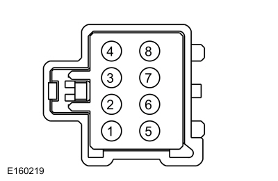 C3034-7, Component Side
|
Is the resistance greater than 2M ohms?
| No |
INSTALL a new backrest blower motor.
REFER to: Front Seat Backrest Blower Motor (501-10A Front Seats, Removal and Installation).
|
|
| T4 CHECK THE DRIVER SEAT BACKREST BLOWER MOTOR THERMISTOR |
-
Measure the component side resistance between:
|
Positive Lead
|
Measurement / Action
|
Negative Lead
|
 C3034-5, Component Side
|

|
 C3034-8, Component Side
|
-
Compare the measured resistance value with the following table:
|
Ambient Temperature
|
Resistance
|
|
0-10° C (32-50° F)
|
2,782-1,663 ohms
|
|
10-20° C (50-68° F)
|
1,837-1,140 ohms
|
|
20-30° C (68-86° F)
|
1,260-806 ohms
|
|
30-40° C (86-104° F)
|
893-570 ohms
|
|
40-50° C (104-122° F)
|
630-428 ohms
|
Is the resistance within the limits indicated?
| No |
INSTALL a new backrest blower motor.
REFER to: Front Seat Backrest Blower Motor (501-10A Front Seats, Removal and Installation).
|
|
| T5 CHECK THE DRIVER SEAT BACKREST BLOWER MOTOR CIRCUITS FOR A SHORT TO VOLTAGE |
-
 WARNING:
Turn the ignition OFF and wait one minute to
deplete the backup power supply. Failure to follow this instruction may
result in serious personal injury or death in the event of an accidental
deployment.
Ignition OFF.
WARNING:
Turn the ignition OFF and wait one minute to
deplete the backup power supply. Failure to follow this instruction may
result in serious personal injury or death in the event of an accidental
deployment.
Ignition OFF.
-
Disconnect: Driver Side Airbag In-line C3368.
-
Disconnect: DSM
C341D and C341E.
-
Connect: Driver Backrest Blower Motor C3034.
-
Measure:
Click to display connectors
|
Positive Lead
|
Measurement / Action
|
Negative Lead
|
|
C341D-4
|

|
Ground
|
|
C341D-5
|

|
Ground
|
|
C341D-15
|

|
Ground
|
|
C341D-9
|

|
Ground
|
-
Measure:
Click to display connectors
|
Positive Lead
|
Measurement / Action
|
Negative Lead
|
|
C341E-5
|

|
Ground
|
|
C341E-1
|

|
Ground
|
|
C341E-10
|

|
Ground
|
Are any voltages present?
| Yes |
REPAIR the affected circuit. GO to T13
|
|
| T6 CHECK THE DRIVER SEAT BACKREST BLOWER MOTOR CIRCUITS FOR A SHORT TO GROUND |
-
Measure:
Click to display connectors
|
Positive Lead
|
Measurement / Action
|
Negative Lead
|
|
C341D-4
|

|
Ground
|
|
C341D-5
|

|
Ground
|
|
C341D-15
|

|
Ground
|
|
C341D-9
|

|
Ground
|
-
Measure:
Click to display connectors
|
Positive Lead
|
Measurement / Action
|
Negative Lead
|
|
C341E-5
|

|
Ground
|
|
C341E-1
|

|
Ground
|
|
C341E-10
|

|
Ground
|
Are the resistances greater than 10,000 ohms?
|
| T7 CHECK THE DRIVER SEAT BACKREST BLOWER MOTOR CIRCUITS FOR A SHORT TO GROUND WITH THE BACKREST BLOWER MOTOR DISCONNECTED |
-
Disconnect: Driver Backrest Blower Motor C3034.
-
Measure:
Click to display connectors
|
Positive Lead
|
Measurement / Action
|
Negative Lead
|
|
C341D-4
|

|
Ground
|
|
C341D-5
|

|
Ground
|
|
C341D-15
|

|
Ground
|
|
C341D-9
|

|
Ground
|
-
Measure:
Click to display connectors
|
Positive Lead
|
Measurement / Action
|
Negative Lead
|
|
C341E-5
|

|
Ground
|
|
C341E-1
|

|
Ground
|
|
C341E-10
|

|
Ground
|
Are the resistances greater than 10,000 ohms?
| Yes |
INSTALL a new backrest blower motor.
REFER to: Front Seat Backrest Blower Motor (501-10A Front Seats, Removal and Installation).
GO to T13
|
|
| T8 CHECK THE DRIVER SEAT BACKREST BLOWER MOTOR CIRCUITS FOR A SHORT TO GROUND WITH THE CUSHION BLOWER MOTOR DISCONNECTED |
-
Disconnect: Driver Cushion Blower Motor C3035.
-
Measure:
Click to display connectors
|
Positive Lead
|
Measurement / Action
|
Negative Lead
|
|
C341D-4
|

|
Ground
|
|
C341D-5
|

|
Ground
|
|
C341D-15
|

|
Ground
|
|
C341D-9
|

|
Ground
|
-
Measure:
Click to display connectors
|
Positive Lead
|
Measurement / Action
|
Negative Lead
|
|
C341E-5
|

|
Ground
|
|
C341E-1
|

|
Ground
|
|
C341E-10
|

|
Ground
|
Are the resistances greater than 10,000 ohms?
| Yes |
REPAIR the affected circuit. GO to T13
|
| No |
INSTALL a new cushion blower motor.
REFER to: Front Seat Cushion Blower Motor (501-10A Front Seats, Removal and Installation).
GO to T13
|
|
| T9 CHECK THE DRIVER SEAT BACKREST BLOWER MOTOR CIRCUITS FOR AN OPEN |
-
Disconnect: Driver Backrest Blower Motor C3034.
-
Measure:
Click to display connectors
|
Positive Lead
|
Measurement / Action
|
Negative Lead
|
|
C341D-4
|

|
C3034-3
|
|
C341D-5
|

|
C3034-1
|
|
C341D-15
|

|
C3034-2
|
|
C341D-9
|

|
C3034-4
|
-
Measure:
Click to display connectors
|
Positive Lead
|
Measurement / Action
|
Negative Lead
|
|
C341E-5
|

|
C3034-5
|
|
C341E-1
|

|
C3034-8
|
|
C341E-10
|

|
C3034-7
|
Are the resistances less than 3 ohms?
| No |
REPAIR the affected circuit. GO to T13
|
|
| T10 CHECK THE DRIVER SEAT BACKREST BLOWER MOTOR CIRCUITS FOR A SHORT TOGETHER |
-
Disconnect: Driver Cushion Blower Motor C3035.
-
Measure:
Click to display connectors
|
Positive Lead
|
Measurement / Action
|
Negative Lead
|
|
C3034-1
|

|
C3034-2
|
|
C3034-3
|

|
C3034-4
|
|
C3034-3
|

|
C3034-7
|
|
C3034-4
|

|
C3034-7
|
|
C3034-5
|

|
C3034-8
|
Are the resistances greater than 10,000 ohms?
| No |
REPAIR the affected circuits. GO to T13
|
|
| T11 DETERMINE BACKREST BLOWER MOTOR OR SCME (FRONT SEAT CLIMATE CONTROL MODULE)
FAILURE |
-
Remove the backrest blower motor from the driver seat.
REFER to: Front Seat Backrest Blower Motor (501-10A Front Seats, Removal and Installation).
-
Remove the backrest blower motor from the passenger seat and install it on the driver seat.
-
Connect: Driver Backrest Blower Motor C3034.
-
Connect: DSM
C341D and C341E.
-
Start the engine and check operation of the driver seat climate controlled seat system.
Does the seat operate with the cushion blower motor from the other seat installed?
| Yes |
INSTALL a new backrest blower motor.
REFER to: Front Seat Backrest Blower Motor (501-10A Front Seats, Removal and Installation).
GO to T13
|
|
| T12 CHECK THE SCME (FRONT SEAT CLIMATE CONTROL MODULE)
OPERATION |
-
Disconnect and inspect all of the DSM connectors.
-
Repair:
-
corrosion (install new connector or terminals - clean module pins)
-
damaged or bent pins - install new terminals/pins as necessary
-
pushed-out pins - install new pins as necessary
-
Reconnect the DSM connectors. Make sure they seat and latch correctly.
-
NOTE:
Do not reconnect Driver Side Airbag In-Line C3368 at this time.
Reconnect all previously disconnected connectors.
-
Operate the system and determine if the concern is still present.
Is the concern still present?
| Yes |
CHECK OASIS for any applicable Technical Service Bulletins (TSBs). If a TSB exists for this concern, DISCONTINUE this test and FOLLOW TSB instructions. If no Technical Service Bulletins (TSBs) address this concern, INSTALL a new DSM.
REFER to: Driver Front Seat Module (DSM) (501-10A Front Seats, Removal and Installation).
GO to T13
|
| No |
The system is operating correctly at this time. The
concern may have been caused by module connections. ADDRESS the root
cause of any connector or pin issues. GO to T13
|
|
| T13 CHECK FOR SRS (SUPPLEMENTAL RESTRAINT SYSTEM)
DIAGNOSTIC TROUBLE CODES (DTCS) |
-
 WARNING:
Turn the ignition OFF and wait one minute to
deplete the backup power supply. Failure to follow this instruction may
result in serious personal injury or death in the event of an accidental
deployment.
Ignition OFF.
WARNING:
Turn the ignition OFF and wait one minute to
deplete the backup power supply. Failure to follow this instruction may
result in serious personal injury or death in the event of an accidental
deployment.
Ignition OFF.
-
Connect: Driver Side Airbag In-line C3368.
-
Connect all previously disconnected connectors.
-
Using a diagnostic scan tool, clear the RCM Diagnostic Trouble Codes (DTCs).
-
Cycle the ignition OFF then ON.
-
Using a diagnostic scan tool, perform RCM self-test.
Are any RCM Diagnostic Trouble Codes (DTCs) retrieved during self-test?
| Yes |
REFER to: Airbag Supplemental Restraint System (SRS) (501-20B Supplemental Restraint System, Diagnosis and Testing).
|
| No |
Repair is complete. RETURN the vehicle to the customer.
|
|
DTC B120B:01, B120B:98, B14BC:01, B14BC:11, B14BC:12, B14BC:13, B14BC:1A and B14C2:11
Refer to Wiring Diagrams Cell 119 for schematic and connector information.
Normal Operation and Fault Conditions
REFER to: Front Seats - System Operation and Component Description (501-10A Front Seats, Description and Operation).
DTC Fault Trigger Conditions
|
DTC
|
Description
|
Fault Trigger Conditions
|
|
B120B:01
|
Passenger Seat Back Temperature Sensor: General Electrical Failure
|
If the passenger seat back blower motor temperature is outside the maximum temperature range, the SCME shuts down the passenger seat system and sets this DTC.
|
|
B120B:98
|
Passenger Seat Back Temperature Sensor: Component or System Over Temperature
|
If the passenger seat back blower motor temperature is outside the maximum temperature range, the SCME shuts down the passenger seat system and sets this DTC.
|
|
B14BC:01
|
Passenger Seat Back Thermal Electric Device: General Electrical Failure
|
If the outputs to the passenger seat back
thermal electric device are shorted to ground or current flow is above a
programmed threshold, the SCME shuts down the passenger seat system and sets this DTC.
|
|
B14BC:11
|
Passenger Seat Back Thermal Electric Device: Circuit Short To Ground
|
If the outputs to the passenger seat back
thermal electric device are shorted to ground or current flow is above a
programmed threshold, the SCME shuts down the passenger seat system and sets this DTC.
|
|
B14BC:12
|
Passenger Seat Back Thermal Electric Device: Circuit Short To Battery
|
If the outputs to the passenger seat back
thermal electric device are shorted to voltage or current flow is below a
programmed threshold, the SCME shuts down the passenger seat system and sets this DTC.
|
|
B14BC:13
|
Passenger Seat Back Thermal Electric Device: Circuit Open
|
If the outputs to the passenger seat back
thermal electric device are disconnected, open or current flow is below a
programmed threshold, the SCME shuts down the passenger seat system and sets this DTC.
|
|
B14BC:1A
|
Passenger Seat Back Thermal Electric Device: Circuit Resistance Below Threshold
|
If the current flow of the outputs to the
passenger seat back thermal electric device is above a programmed
threshold, the SCME shuts down the passenger seat system and sets this DTC.
|
|
B14C2:11
|
Passenger Seat Back Blower: Circuit Short To Ground
|
If the current to the passenger seat back blower exceeds a programmed threshold, the SCME shuts down the passenger seat system and sets this DTC.
|
Possible Causes
-
Wiring, terminals or connectors
-
Backrest blower motor
-
DSM
PINPOINT TEST U : DTC B120B:01, B120B:98, B14BC:01, B14BC:11, B14BC:12, B14BC:13, B14BC:1A AND B14C2:11
 WARNING:
Incorrect repair techniques or actions can cause an
accidental Supplemental Restraint System (SRS) deployment. Never
compromise or depart from these instructions. Failure to precisely
follow all instructions could result in serious personal injury from an
accidental deployment.
WARNING:
Incorrect repair techniques or actions can cause an
accidental Supplemental Restraint System (SRS) deployment. Never
compromise or depart from these instructions. Failure to precisely
follow all instructions could result in serious personal injury from an
accidental deployment.
|
| U1 CHECK THE RESISTANCE OF THE PASSENGER SEAT BACKREST BLOWER MOTOR THERMO-ELECTRIC DEVICE (TED) |
-
Disconnect: Passenger Backrest Blower Motor C3039.
-
NOTE:
Do not operate the heated/climate seat for 60
minutes before carrying out any diagnostics. Allow the seat to rest for
60 minutes until it has reached ambient temperature.
Measure the component side resistance between:
|
Positive Lead
|
Measurement / Action
|
Negative Lead
|
 C3039-1, Component Side
|

|
 C3039-2, Component Side
|
Is the resistance between 0.9 and 10 ohms?
| No |
INSTALL a new backrest blower motor.
REFER to: Front Seat Backrest Blower Motor (501-10A Front Seats, Removal and Installation).
|
|
| U2 CHECK THE RESISTANCE OF THE PASSENGER SEAT BACKREST BLOWER MOTOR |
-
NOTE:
The ohmmeter must be connected with the positive
lead to pin 3 and the negative lead to pin 4 when measuring. Ohmmeter
leads incorrectly connected results in false readings and leads to
incorrect identification of components that are not faulty.
Measure the component side resistance between:
|
Positive Lead
|
Measurement / Action
|
Negative Lead
|
 C3039-3, Component Side
|

|
 C3039-4, Component Side
|
Is the resistance between 4,000 and 10,000 ohms?
| No |
INSTALL a new backrest blower motor.
REFER to: Front Seat Backrest Blower Motor (501-10A Front Seats, Removal and Installation).
|
|
| U3 CHECK THE PASSENGER SEAT BACKREST BLOWER MOTOR SPEED CONTROL AND BLOWER OUTPUT CIRCUITS FOR AN INTERNAL SHORT TOGETHER |
-
Measure the component side resistance between:
|
Positive Lead
|
Measurement / Action
|
Negative Lead
|
 C3039-3, Component Side
|

|
 C3039-7, Component Side
|
Is the resistance greater than 2M ohms?
| No |
INSTALL a new backrest blower motor.
REFER to: Front Seat Backrest Blower Motor (501-10A Front Seats, Removal and Installation).
|
|
| U4 CHECK THE PASSENGER SEAT BACKREST BLOWER MOTOR THERMISTOR |
-
Measure the component side resistance between:
|
Positive Lead
|
Measurement / Action
|
Negative Lead
|
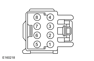 C3039-5, Component Side
|

|
 C3039-8, Component Side
|
-
Compare the measured resistance value with the following table:
|
Ambient Temperature
|
Resistance
|
|
0-10° C (32-50° F)
|
2,782-1,663 ohms
|
|
10-20° C (50-68° F)
|
1,837-1,140 ohms
|
|
20-30° C (68-86° F)
|
1,260-806 ohms
|
|
30-40° C (86-104° F)
|
893-570 ohms
|
|
40-50° C (104-122° F)
|
630-428 ohms
|
Is the resistance within the limits indicated?
| No |
INSTALL a new backrest blower motor.
REFER to: Front Seat Backrest Blower Motor (501-10A Front Seats, Removal and Installation).
|
|
| U5 CHECK THE PASSENGER SEAT BACKREST BLOWER MOTOR CIRCUITS FOR A SHORT TO VOLTAGE |
-
 WARNING:
Turn the ignition OFF and wait one minute to
deplete the backup power supply. Failure to follow this instruction may
result in serious personal injury or death in the event of an accidental
deployment.
Ignition OFF.
WARNING:
Turn the ignition OFF and wait one minute to
deplete the backup power supply. Failure to follow this instruction may
result in serious personal injury or death in the event of an accidental
deployment.
Ignition OFF.
-
Disconnect: Driver Side Airbag In-line C3368.
-
Disconnect: Passenger Side Airbag In-line C3206.
-
Disconnect: DSM
C341D and C341E.
-
Connect: Passenger Backrest Blower Motor C3039.
-
Measure:
Click to display connectors
|
Positive Lead
|
Measurement / Action
|
Negative Lead
|
|
C341D-3
|

|
Ground
|
|
C341D-12
|

|
Ground
|
|
C341D-16
|

|
Ground
|
|
C341D-11
|

|
Ground
|
-
Measure:
Click to display connectors
|
Positive Lead
|
Measurement / Action
|
Negative Lead
|
|
C341E-3
|

|
Ground
|
|
C341E-2
|

|
Ground
|
|
C341E-8
|

|
Ground
|
Are any voltages present?
| Yes |
REPAIR the affected circuit. GO to U13
|
|
| U6 CHECK THE PASSENGER SEAT BACKREST BLOWER MOTOR CIRCUITS FOR A SHORT TO GROUND |
-
Measure:
Click to display connectors
|
Positive Lead
|
Measurement / Action
|
Negative Lead
|
|
C341D-3
|

|
Ground
|
|
C341D-12
|

|
Ground
|
|
C341D-16
|

|
Ground
|
|
C341D-11
|

|
Ground
|
-
Measure:
Click to display connectors
|
Positive Lead
|
Measurement / Action
|
Negative Lead
|
|
C341E-3
|

|
Ground
|
|
C341E-2
|

|
Ground
|
|
C341E-8
|

|
Ground
|
Are the resistances greater than 10,000 ohms?
|
| U7 CHECK THE PASSENGER SEAT BACKREST BLOWER MOTOR CIRCUITS FOR A SHORT TO GROUND WITH THE BACKREST BLOWER MOTOR DISCONNECTED |
-
Disconnect: Passenger Backrest Blower Motor C3039.
-
Measure:
Click to display connectors
|
Positive Lead
|
Measurement / Action
|
Negative Lead
|
|
C341D-3
|

|
Ground
|
|
C341D-12
|

|
Ground
|
|
C341D-16
|

|
Ground
|
|
C341D-11
|

|
Ground
|
-
Measure:
Click to display connectors
|
Positive Lead
|
Measurement / Action
|
Negative Lead
|
|
C341E-3
|

|
Ground
|
|
C341E-2
|

|
Ground
|
|
C341E-8
|

|
Ground
|
Are the resistances greater than 10,000 ohms?
| Yes |
INSTALL a new backrest blower motor.
REFER to: Front Seat Backrest Blower Motor (501-10A Front Seats, Removal and Installation).
GO to U13
|
|
| U8 CHECK THE PASSENGER SEAT BACKREST BLOWER MOTOR CIRCUITS FOR A SHORT TO GROUND WITH THE CUSHION BLOWER MOTOR DISCONNECTED |
-
Disconnect: Passenger Cushion Blower Motor C3040.
-
Measure:
Click to display connectors
|
Positive Lead
|
Measurement / Action
|
Negative Lead
|
|
C341D-3
|

|
Ground
|
|
C341D-12
|

|
Ground
|
|
C341D-16
|

|
Ground
|
|
C341D-11
|

|
Ground
|
-
Measure:
Click to display connectors
|
Positive Lead
|
Measurement / Action
|
Negative Lead
|
|
C341E-3
|

|
Ground
|
|
C341E-2
|

|
Ground
|
|
C341E-8
|

|
Ground
|
Are the resistances greater than 10,000 ohms?
| Yes |
REPAIR the affected circuit. GO to U13
|
| No |
INSTALL a new cushion blower motor.
REFER to: Front Seat Cushion Blower Motor (501-10A Front Seats, Removal and Installation).
GO to U13
|
|
| U9 CHECK THE PASSENGER SEAT BACKREST BLOWER MOTOR CIRCUITS FOR AN OPEN |
-
Disconnect: Passenger Backrest Blower Motor C3039.
-
Measure:
Click to display connectors
|
Positive Lead
|
Measurement / Action
|
Negative Lead
|
|
C341D-3
|

|
C3039-3
|
|
C341D-12
|

|
C3039-1
|
|
C341D-16
|

|
C3039-2
|
|
C341D-11
|

|
C3039-4
|
-
Measure:
Click to display connectors
|
Positive Lead
|
Measurement / Action
|
Negative Lead
|
|
C341E-3
|

|
C3039-5
|
|
C341E-2
|

|
C3039-8
|
|
C341E-8
|

|
C3039-7
|
Are the resistances less than 3 ohms?
| No |
REPAIR the affected circuit. GO to U13
|
|
| U10 CHECK THE PASSENGER SEAT BACKREST BLOWER MOTOR CIRCUITS FOR A SHORT TOGETHER |
-
Disconnect: Passenger Cushion Blower Motor C3040.
-
Measure:
Click to display connectors
|
Positive Lead
|
Measurement / Action
|
Negative Lead
|
|
C3039-1
|

|
C3039-2
|
|
C3039-3
|

|
C3039-4
|
|
C3039-3
|

|
C3039-7
|
|
C3039-4
|

|
C3039-7
|
|
C3039-5
|

|
C3039-8
|
Are the resistances greater than 10,000 ohms?
| No |
REPAIR the affected circuits. GO to U13
|
|
| U11 DETERMINE BACKREST BLOWER MOTOR OR SCME (FRONT SEAT CLIMATE CONTROL MODULE)
FAILURE |
-
Remove the backrest blower motor from the passenger seat.
REFER to: Front Seat Backrest Blower Motor (501-10A Front Seats, Removal and Installation).
-
Remove the backrest blower motor from the driver seat and install it on the passenger seat.
-
Connect: Passenger Backrest Blower Motor C3039.
-
Connect: DSM
C341D and C341E.
-
Start the engine and check operation of the passenger seat climate controlled seat system.
Does the seat operate with the cushion blower motor from the other seat installed?
| Yes |
INSTALL a new backrest blower motor.
REFER to: Front Seat Backrest Blower Motor (501-10A Front Seats, Removal and Installation).
GO to U13
|
|
| U12 CHECK THE SCME (FRONT SEAT CLIMATE CONTROL MODULE)
OPERATION |
-
Disconnect and inspect all of the DSM connectors.
-
Repair:
-
corrosion (install new connector or terminals - clean module pins)
-
damaged or bent pins - install new terminals/pins as necessary
-
pushed-out pins - install new pins as necessary
-
Reconnect the DSM connectors. Make sure they seat and latch correctly.
-
NOTE:
Do not reconnect Driver Side Airbag In-Line C3368 or Passenger Side Airbag In-Line C3206 at this time.
Reconnect all previously disconnected connectors.
-
Operate the system and determine if the concern is still present.
Is the concern still present?
| Yes |
CHECK OASIS for any applicable Technical Service Bulletins (TSBs). If a TSB exists for this concern, DISCONTINUE this test and FOLLOW TSB instructions. If no Technical Service Bulletins (TSBs) address this concern, INSTALL a new DSM.
REFER to: Driver Front Seat Module (DSM) (501-10A Front Seats, Removal and Installation).
GO to U13
|
| No |
The system is operating correctly at this time. The
concern may have been caused by module connections. ADDRESS the root
cause of any connector or pin issues. GO to U13
|
|
| U13 CHECK FOR SRS (SUPPLEMENTAL RESTRAINT SYSTEM)
DIAGNOSTIC TROUBLE CODES (DTCS) |
-
 WARNING:
Turn the ignition OFF and wait one minute to
deplete the backup power supply. Failure to follow this instruction may
result in serious personal injury or death in the event of an accidental
deployment.
Ignition OFF.
WARNING:
Turn the ignition OFF and wait one minute to
deplete the backup power supply. Failure to follow this instruction may
result in serious personal injury or death in the event of an accidental
deployment.
Ignition OFF.
-
Connect: Driver Side Airbag In-line C3368.
-
Connect: Passenger Side Airbag In-line C3206.
-
Connect all previously disconnected connectors.
-
Using a diagnostic scan tool, clear the RCM Diagnostic Trouble Codes (DTCs).
-
Cycle the ignition OFF then ON.
-
Using a diagnostic scan tool, perform RCM self-test.
Are any RCM Diagnostic Trouble Codes (DTCs) retrieved during self-test?
| Yes |
REFER to: Airbag Supplemental Restraint System (SRS) (501-20B Supplemental Restraint System, Diagnosis and Testing).
|
| No |
Repair is complete. RETURN the vehicle to the customer.
|
|
DTC: U0100:00
Refer to Wiring Diagrams Cell 14 for schematic and connector information.
Normal Operation and Fault Conditions
The DSM and the PCM communicate using the HS-CAN1 and MS-CAN.
DTC Fault Trigger Conditions
|
DTC
|
Description
|
Fault Trigger Conditions
|
|
U0100:00
|
Lost Communication with ECM/PCM "A": No Sub Type Information
|
Set by the DSM whenever it has lost communication to the PCM for 5 seconds or longer while DSM input voltage is between 10 and 15.5 volts.
|
Possible Causes
-
Module communication
-
DSM
-
PCM
PINPOINT TEST V : DTC: U0100:00
| V1 VERIFY CUSTOMER CONCERN |
-
Verify there is an observable symptom present.
Is an observable symptom present?
| No |
The system is operating normally at this time. The DTC may have been set due to high network traffic or intermittent fault condition.
|
|
| V2 CHECK THE COMMUNICATION NETWORK |
-
Using a diagnostic scan tool, perform the network test.
Does the PCM pass the network test?
| No |
REFER to: Communications Network (418-00 Module Communications Network, Diagnosis and Testing).
|
|
| V3 RECHECK THE DSM (DRIVER FRONT SEAT MODULE)
DIAGNOSTIC TROUBLE CODES (DTCS) |
|
NOTE:
If new modules were installed prior to the DTC being set, the module configuration may be incorrectly set during PMI or the PMI may not have been carried out.
-
Using a diagnostic scan tool, clear the Continuous Memory Diagnostic Trouble Codes (CMDTCs).
-
Using a diagnostic scan tool, repeat the DSM self-test.
Is DTC U0100:00 still present?
| No |
The system is operating correctly at this time. The DTC may have been set due to high network traffic or intermittent fault condition.
|
|
| V4 CHECK FOR DTC U0100:00 IN OTHER MODULES |
|
NOTE:
If new modules were installed prior to the DTC being set, the module configuration may be incorrectly set during PMI or the PMI may not have been carried out.
-
Using a diagnostic scan tool, clear the Continuous Memory Diagnostic Trouble Codes (CMDTCs).
-
Using a diagnostic scan tool, retrieve the
Continuous Memory Diagnostic Trouble Codes (CMDTCs) from all modules.
Is DTC U0100:00 set in other modules?
| Yes |
 Click here to access Guided Routine (PCM).
 Internet Explorer version 11 or greater is required to perform this Pinpoint Test. Internet Explorer version 11 or greater is required to perform this Pinpoint Test.
|
| No |
INSTALL a new DSM.
REFER to: Driver Front Seat Module (DSM) (501-10A Front Seats, Removal and Installation).
|
|
DTC: U0140:00
Refer to Wiring Diagrams Cell 14 for schematic and connector information.
Normal Operation and Fault Conditions
The SCME and the BCM communicate using the MS-CAN.
DTC Fault Trigger Conditions
|
DTC
|
Description
|
Fault Trigger Conditions
|
|
U0140:00
|
Lost Communication with Body Control Module: No Sub Type Information
|
Set by the SCME whenever it has lost communication to the BCM for 5 seconds or longer while SCME input voltage is between 10 and 15.5 volts.
|
Possible Causes
-
Module communication
-
SCME
-
BCM
PINPOINT TEST W : DTC: U0140:00
| W1 VERIFY CUSTOMER CONCERN |
-
Verify there is an observable symptom present.
Is an observable symptom present?
| No |
The system is operating normally at this time. The DTC may have been set due to high network traffic or intermittent fault condition.
|
|
| W2 CHECK THE COMMUNICATION NETWORK |
-
Using a diagnostic scan tool, perform the network test.
Does the BCM pass the network test?
| No |
REFER to: Communications Network (418-00 Module Communications Network, Diagnosis and Testing).
|
|
| W3 RECHECK THE SCME (FRONT SEAT CLIMATE CONTROL MODULE)
DIAGNOSTIC TROUBLE CODES (DTCS) |
|
NOTE:
If new modules were installed prior to the DTC being set, the module configuration may be incorrectly set during PMI or the PMI may not have been carried out.
-
Using a diagnostic scan tool, clear the Continuous Memory Diagnostic Trouble Codes (CMDTCs).
-
Using a diagnostic scan tool, repeat the SCME self-test.
Is DTC U0140:00 still present?
| No |
The system is operating correctly at this time. The DTC may have been set due to high network traffic or intermittent fault condition.
|
|
| W4 CHECK FOR DTC U0140:00 IN OTHER MODULES |
|
NOTE:
If new modules were installed prior to the DTC being set, the module configuration may be incorrectly set during PMI or the PMI may not have been carried out.
-
Using a diagnostic scan tool, clear the Continuous Memory Diagnostic Trouble Codes (CMDTCs).
-
Using a diagnostic scan tool, retrieve the
Continuous Memory Diagnostic Trouble Codes (CMDTCs) from all modules.
Is DTC U0140:00 set in other modules?
| Yes |
 Click here to access Guided Routine (BCM).
 Internet Explorer version 11 or greater is required to perform this Pinpoint Test. Internet Explorer version 11 or greater is required to perform this Pinpoint Test.
|
| No |
INSTALL a new DSM.
REFER to: Driver Front Seat Module (DSM) (501-10A Front Seats, Removal and Installation).
|
|
DTC: U0257:00
Refer to Wiring Diagrams Cell 14 for schematic and connector information.
Normal Operation and Fault Conditions
The SCME and the FCIM communicate using the HS-CAN3 and MS-CAN.
DTC Fault Trigger Conditions
|
DTC
|
Description
|
Fault Trigger Conditions
|
|
U0257:00
|
Lost Communication with Front Controls / Display Interface Module: No Sub Type Information
|
Set by the SCME whenever it has lost communication to the FCIM while SCME input voltage is between 10 and 15.5 volts.
|
Possible Causes
-
Module communication
-
SCME
-
FCIM
PINPOINT TEST X : DTC: U0257:00
| X1 VERIFY CUSTOMER CONCERN |
-
Verify there is an observable symptom present.
Is an observable symptom present?
| No |
The system is operating normally at this time. The DTC may have been set due to high network traffic or intermittent fault condition.
|
|
| X2 CHECK THE COMMUNICATION NETWORK |
-
Using a diagnostic scan tool, perform the network test.
Does the FCIM pass the network test?
| No |
REFER to: Communications Network (418-00 Module Communications Network, Diagnosis and Testing).
|
|
| X3 RECHECK THE SCME (FRONT SEAT CLIMATE CONTROL MODULE)
DIAGNOSTIC TROUBLE CODES (DTCS) |
|
NOTE:
If new modules were installed prior to the DTC being set, the module configuration may be incorrectly set during PMI or the PMI may not have been carried out.
-
Using a diagnostic scan tool, clear the Continuous Memory Diagnostic Trouble Codes (CMDTCs).
-
Using a diagnostic scan tool, repeat the SCME self-test.
Is DTC U0257:00 still present?
| No |
The system is operating correctly at this time. The DTC may have been set due to high network traffic or intermittent fault condition.
|
|
| X4 CHECK FOR DTC U0257:00 IN OTHER MODULES |
|
NOTE:
If new modules were installed prior to the DTC being set, the module configuration may be incorrectly set during PMI or the PMI may not have been carried out.
-
Using a diagnostic scan tool, clear the Continuous Memory Diagnostic Trouble Codes (CMDTCs).
-
Using a diagnostic scan tool, retrieve the
Continuous Memory Diagnostic Trouble Codes (CMDTCs) from all modules.
Is DTC U0140:00 set in other modules?
| Yes |
 Click here to access Guided Routine (FCIM).
 Internet Explorer version 11 or greater is required to perform this Pinpoint Test. Internet Explorer version 11 or greater is required to perform this Pinpoint Test.
|
| No |
INSTALL a new DSM.
REFER to: Driver Front Seat Module (DSM) (501-10A Front Seats, Removal and Installation).
|
|
DTC: U0212:00
Refer to Wiring Diagrams Cell 14 for schematic and connector information.
Normal Operation and Fault Conditions
The DSM and the SCCM communicate using the CAN.
DTC Fault Trigger Conditions
|
DTC
|
Description
|
Fault Trigger Conditions
|
|
U0212:00
|
Lost Communication with Steering Column Control Module: No Sub Type Information
|
Set by the DSM whenever it has lost communication to the BCM for 5 seconds or longer while DSM input voltage is between 10 and 15.5 volts.
|
Possible Causes
-
Module communication
-
DSM
-
SCCM
PINPOINT TEST Y : DTC: U0212:00
| Y1 VERIFY CUSTOMER CONCERN |
-
Verify there is an observable symptom present.
Is an observable symptom present?
| No |
The system is operating normally at this time. The DTC may have been set due to high network traffic or intermittent fault condition.
|
|
| Y2 CHECK THE COMMUNICATION NETWORK |
-
Using a diagnostic scan tool, perform the network test.
Does the SCCM pass the network test?
| No |
REFER to: Communications Network (418-00 Module Communications Network, Diagnosis and Testing).
|
|
| Y3 RECHECK THE DSM (DRIVER FRONT SEAT MODULE)
DIAGNOSTIC TROUBLE CODES (DTCS) |
|
NOTE:
If new modules were installed prior to the DTC being set, the module configuration may be incorrectly set during PMI or the PMI may not have been carried out.
-
Using a diagnostic scan tool, clear the Continuous Memory Diagnostic Trouble Codes (CMDTCs).
-
Using a diagnostic scan tool, repeat the DSM self-test.
Is DTC U0212:00 still present?
| No |
The system is operating correctly at this time. The DTC may have been set due to high network traffic or intermittent fault condition.
|
|
| Y4 CHECK FOR DTC U0212:00 IN OTHER MODULES |
|
NOTE:
If new modules were installed prior to the DTC being set, the module configuration may be incorrectly set during PMI or the PMI may not have been carried out.
-
Using a diagnostic scan tool, clear the Continuous Memory Diagnostic Trouble Codes (CMDTCs).
-
Using a diagnostic scan tool, retrieve the
Continuous Memory Diagnostic Trouble Codes (CMDTCs) from all modules.
Is DTC U0212:00 set in other modules?
| Yes |
INSTALL a new SCCM.
REFER to: Steering Column Control Module (SCCM) (211-05 Steering Wheel and Column Electrical Components, Removal and Installation).
|
| No |
INSTALL a new DSM.
REFER to: Driver Front Seat Module (DSM) (501-10A Front Seats, Removal and Installation).
|
|
Component Test(s)
Blower Motor Cooling Performance
NOTE:
This test is intended to check the cooling mode
performance of an operational climate controlled seat backrest or
cushion blower motor and verify it is cooling inlet air at the blower
motor (ambient cabin air) between 6-8° C (10-14° F).
NOTE:
Make sure the vehicle is out of direct sunlight and is
in an area with a stable air temperature when testing the climate
controlled seat system.
NOTE:
For correct temperature measurements, the seat being tested should be occupied.
-
Using a diagnostic scan tool, monitor the following SCME Parameter Identifications (PIDs):
-
Seat Cushion Temperature - Driver (SEAT_CSH_TMP_D)
-
Seat Back Temperature - Driver (SEAT_BK_TMP_D)
-
Seat Cushion Temperature - Passenger (SEAT_CSH_TMP_P)
-
Seat Back Temperature - Passenger (SEAT_BK_TMP_P)
-
Climate Controlled Seat System State - Driver (CLIMATE_SEAT_D)
-
Climate Controlled Seat System State - Passenger (CLIMATE_SEAT_P)
-
Any initial PID
value of greater than 205° C (401° F) or less than 2° C (36° F)
indicates a system hardware failure. Do not proceed with this test. GO
to Symptom Chart or SCME
DTC Chart for diagnostic direction.
-
Gain access to the seat cushion and backrest blower
motors and use a suitable thermocouple temperature measuring device to
monitor the air inlet temperature.
-
Place the temperature probe near each blower motor air filter.
-
NOTE:
The engine must be running to operate the climate controlled seat system and carry out this test.
Operate system in high cool mode and measure the
temperature at the cushion blower motor filter using the thermocouple
device.
-
Secure the temperature probe at the cushion blower motor and record the air inlet temperature.
-
Use a diagnostic scan tool to measure the cushion blower motor PID temperature and record the value.
-
Monitor the STATE Parameter Identifications (PIDs) to verify the system is operating. If during testing, a PID
value indicates a fault has occurred (putting the system into recovery
mode) the seat has failed the test. Do not continue. Return to the
diagnostic routine.
-
Subtract the cushion blower motor PID temperature from the cushion air inlet temperature and record the temperature difference value.
-
Continue to operate the system in high cool mode and use
the thermocouple device to measure the temperature at the backrest
blower motor filter.
-
Secure the temperature probe at the backrest blower
motor and close the backrest trim cover before measuring and recording
the air inlet temperature.
-
Use a diagnostic scan tool to measure the backrest blower motor PID temperature and record the value.
-
Monitor the STATE Parameter Identifications (PIDs) to verify the system is operating. If during testing, a PID
value indicates a fault has occurred (putting the system into recovery
mode) the seat has failed the test. Do not continue. Return to the
diagnostic routine.
-
Subtract the backrest blower motor PID temperature from the backrest air inlet temperature and record the value.
-
Compare the cushion and backrest calculated temperature
values. The temperature difference should be between 6-8° C (10-14° F).
-
If the calculated temperature values are not within
these specifications, check the climate controlled seat components for
air duct or filter restrictions, blockages, duct or electrical
disconnections and for incorrect assembly. Repair as needed. If OK,
carry out the SCME self-test and if any Diagnostic Trouble Codes (DTCs) are retrieved, go to SCME
DTC Chart for diagnostic direction. Return to the diagnostic routine.
Repair
NOTE:
Click here to view a video version of the seat heater mat removal and installation. View
NOTE:
Always install a new heater mat...
Other information:
General Specifications - Rear Parking Aid
Item
Specification
Test object position 1 (P1) and position 5 (P5), distance from rear bumper
30 cm (12 in)
Test object position 2 (P2) and position 4 (P4), distance from rear bumper
91 cm (36 in)
Test object position 3 (P3), distance from rear bumper
152 cm (60 in)
..
Special Tool(s) /
General Equipment
Air Conditioning Service Unit
Air Conditioning Adaptor Kit
Inspection
Recover the refrigerant. Refer to Air Conditioning (A/C)
System Recovery, Evacuation and Charging procedure in Group 412.
Disconnect the condenser from the A/C system. Refer to the appropriate section in Group 412 for the procedure.
Use the corre..

 Seat Heater Mat Installation. General Procedures