Ford Fusion: Front Seats / Front Seat Power Lumbar Assembly. Removal and Installation
Removal
-
Remove the front seat.
Refer to: Front Seat (501-10A Front Seats, Removal and Installation).
-
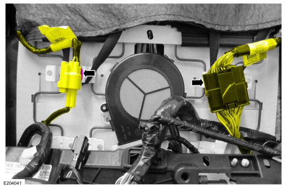
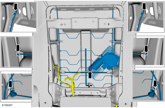
Detach the electrical connector retainers and position the wire harnesses aside.
-
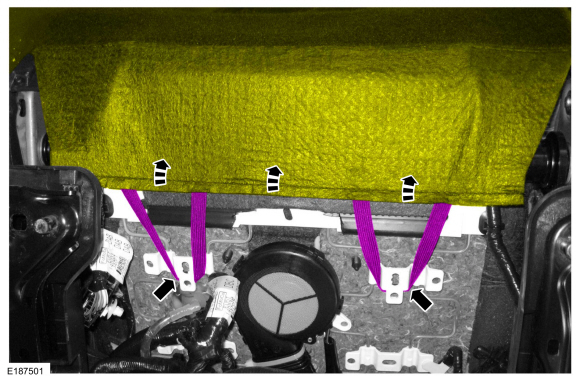
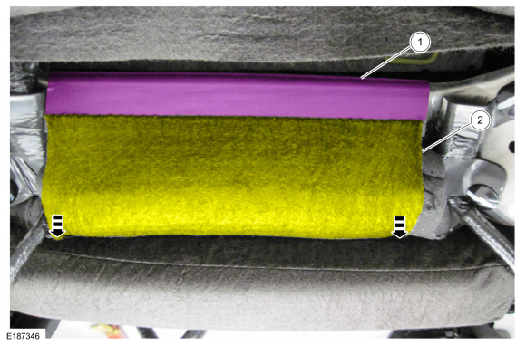
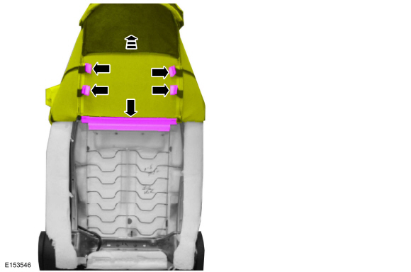
Detach the backrest cover straps and position the backrest cover upward.
-
-
Remove the pin-type retainers.
-
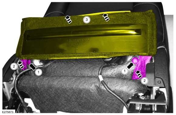
Detach the hook-and-loop strips.
-
Lift the backrest cover flap.
-
Position the front seat backrest cover.
-
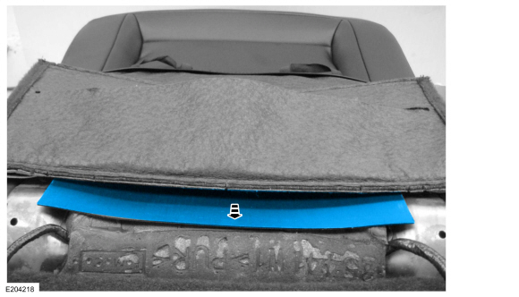
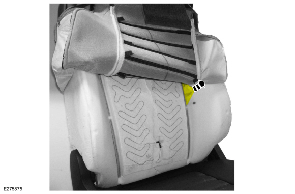
Release the J-clip.
-
Position the backrest cover from between the seat cushion and backrest cushion.
-
Remove the backrest cover insert.
-
NOTICE:
Use care when separating the backrest trim cover
from the hook-and-loop strips or the hook-and-loop strips may be torn
from the backrest foam.
Partially invert the backrest cover enough to access the hog rings.
-
Release the hook-and-loop strips.
-
Invert the backrest cover.
-
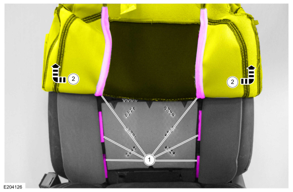
Remove the pin-type retainers from the deployment chute wrap and begin feeding it through the backrest foam.
-
Pull the deployment chute wrap out of the backrest foam.
-
Lift the backrest cover and release the J-clips from the lumbar wires and backrest frame.
-
If equipped.
Remove the backrest blower motor.
Refer to: Front Seat Backrest Blower Motor (501-10A Front Seats, Removal and Installation).
-
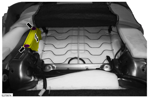
Disconnect the electrical connector, release the J-hooks and remove the power lumbar assembly.
Installation
-
To install, reverse the removal procedure.
Removal
Remove the front seat.
Refer to: Front Seat (501-10A Front Seats, Removal and Installation).
If equipped.
Release the lumbar knob retaining clip and remove the lumbar knob...
Removal
NOTE:
Note the wire harness routing for installation purposes.
Remove the front seat backrest.
Refer to: Front Seat Backrest (501-10A Front Seats, Removal and Installation)...
Other information:
Removal
NOTE:
Removal steps in this procedure may contain installation details.
WARNING:
Turn the ignition OFF and wait one minute to deplete
the backup power supply. Ignition must remain OFF until repair is
complete. Failure to follow this instruction may result in serious
personal injury or death in the event of an accidental deployment...
The system helps reduce fuel consumption
by automatically shutting off and restarting
the engine while your vehicle is stopped.
The engine will restart automatically when
you release the brake pedal. In some
situations, your vehicle may restart
automatically, for example:
To maintain interior comfort
To recharge the battery
Note: Power assist steering is turned off
when the engine is of..
 Front Seat Lumbar Assembly. Removal and Installation
 Front Seat Track. Removal and Installation