Ford Fusion: Handles, Locks, Latches and Entry Systems / Exterior Rear Door Handle Reinforcement. Removal and Installation
Removal
NOTE: Removal steps in this procedure may contain installation details.
-
Remove the rear door latch.
Refer to: Rear Door Latch (501-14 Handles, Locks, Latches and Entry Systems, Removal and Installation).
-
NOTE: This step is only necessary when installing a new component.
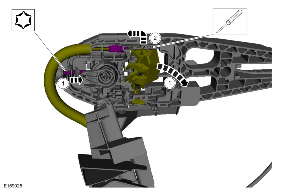
Remove the cable eyelet from the lever.
-
While turning the release screw the handle rotates the lever releasing the tension on the cable.
-
Remove the cable eyelet from the lever.
-
While turning the release screw the handle rotates the lever releasing the tension on the cable.
 |
-
NOTE: This step is only necessary when installing a new component.
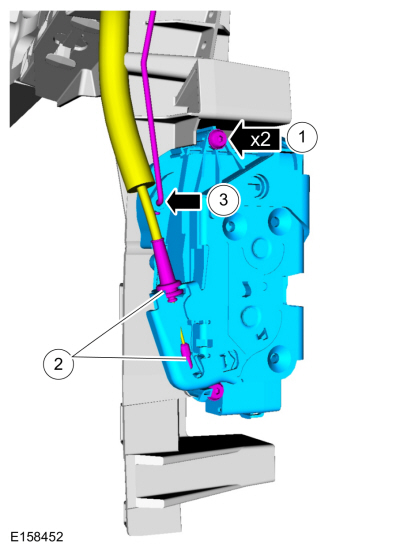
Remove the rear door latch.
-
Remove the screws.
-
Detach and position aside the cable from the rear door latch.
-
Remove the interior rear door handle cable from the rear door latch.
-
Remove the screws.
 |
-
NOTE: This step is only necessary when installing a new component.
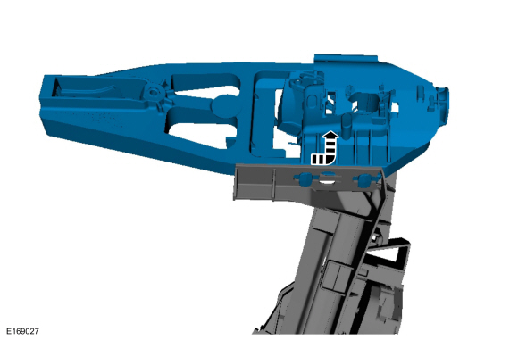
Remove the exterior front door handle reinforcement.
 |
Installation
-
NOTE: This step is only necessary when installing a new component.
Install the exterior front door handle reinforcement.
 |
-
NOTE: This step is only necessary when installing a new component.
Install the rear door latch.
-
Install the screws.
-
Attach and position the cable on the rear door latch.
-
Install the interior rear door handle cable on the rear door latch.
-
Install the screws.
 |
-
NOTE: This step is only necessary when installing a new component.
NOTE: This step must be done correctly or the exterior door handle will not engage the lever on installation.
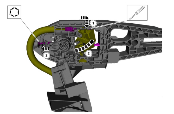
Install the cable eyelet to the lever.
-
Install the cable eyelet to the lever.
-
While keeping tension on the cable and holding the
handle lever in the engaged position, turn the release screw until the
handle lever is positioned against the stop.
-
Install the cable eyelet to the lever.
 |
 Exterior Front Door Handle Reinforcement. Removal and Installation
Removal
NOTE:
LH side shown, RH side similar.
NOTE:
Removal steps in this procedure may contain installation details.
Remove the front door latch...
 Keyless Entry Keypad. Removal and Installation
Removal
NOTE:
The keyless entry keypad is serviced with the front door upper moulding.
Refer to: Front Door Upper Moulding (501-08 Exterior Trim and Ornamentation, Removal and Installation)...
Other information:
Ford Fusion 2013–2020 Owners Manual: Washer Fluid Check. Fuel Filter
Washer Fluid Check WARNING: If you operate your vehicle in temperatures below 40°F (5°C), use washer fluid with antifreeze protection. Failure to use washer fluid with antifreeze protection in cold weather could result in impaired windshield vision and increase the risk of injury or accident...
Ford Fusion 2013–2020 Service Manual: Trough Assembly. Removal and Installation
Removal NOTE: Removal steps in this procedure may contain installation details. Remove the roof opening panel frame. Refer to: Roof Opening Panel Frame (501-17 Roof Opening Panel, Removal and Installation). Remove the roof opening panel shield...
Categories
- Manuals Home
- 2nd Generation Ford Fusion Owners Manual
- 2nd Generation Ford Fusion Service Manual
- Oil Cooler. Removal and Installation
- Memory Function
- Starter Motor. Removal and Installation
- New on site
- Most important about car
Using Seatbelts During Pregnancy
WARNING: Always ride and drive with your seatback upright and properly fasten your seatbelt. Fit the lap portion of the seatbelt snugly and low across the hips. Position the shoulder portion of the seatbelt across your chest. Pregnant women must follow this practice. See the following figure.
