Ford Fusion: Exterior Lighting / Exterior Lighting - System Operation and Component Description. Description and Operation
System Operation
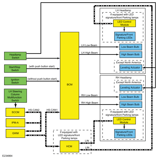
Headlamps - Halogen Headlamps
System Diagram
.jpg)
| Item | Description |
|---|---|
| 1 | HS-CAN2 |
| 2 | BCM |
| 3 | LH low beam |
| 4 | LH high beam |
| 5 | SCCM |
| 6 | Headlamp switch |
| 7 | LH steering column multifunction switch |
| 8 | IPMA |
| 9 | GWM |
| 10 | HS-CAN1 |
| 11 | Start/Stop switch |
| 12 | HCM |
| 13 | LIN |
| 14 | LED control module |
| 15 | RH headlamp |
| 16 | Low beam bulb |
| 17 | If equipped with LED signature/front parking lamps |
| 18 | If equipped with LED signature/front parking lamps |
| 19 | High beam bulb |
| 20 | RH low beam |
| 21 | RH high beam |
| 22 | Low beam bulb |
| 23 | High beam bulb |
| 24 | Leveling actuator |
| 25 | Leveling actuator |
| 26 | Except North America |
| 27 | Except North America |
| 28 | Ignition switch |
| 29 | LIN |
| 30 | Signature/front parking Light Emitting Diodes (LEDs) |
| 31 | LH headlamp |
| 32 | LED control module |
| 33 | If equipped with LED signature/front parking lamps |
| 34 | Signature/front parking Light Emitting Diodes (LEDs) |
| 35 | (without push button start) |
| 36 | (with push button start) |
Network Message Chart
BCM Network Input Messages
| Broadcast Message | Originating Module | Message Purpose |
|---|---|---|
| Headlamp flash to pass status | GWM | Indicates to the BCM a request for the high beams or flash-to-pass. |
GWM Network Input Messages
| Broadcast Message | Originating Module | Message Purpose |
|---|---|---|
| Headlamp flash to pass status | SCCM | Indicates to the GWM a request for the high beams or flash-to-pass. |
SCCM Network Input Messages
| Broadcast Message | Originating Module | Message Purpose |
|---|---|---|
| Auto high beam request | IPMA | Indicates to the SCCM a request for the high beams based on the IPMA camera input. |
Low Beams
The BCM monitors the headlamp switch position by sending voltage signals on multiple circuits to the headlamp switch. There is one circuit for each headlamp switch position. At any given time, one of the signal circuits is switched to ground to indicate the headlamp switch position.
The BCM turns the parking lamps and headlamps on when the ignition is in RUN and the BCM detects a fault from the headlamp switch or wiring. This is normal behavior of the BCM when a fault has been detected with the inputs from the headlamp switch.
The BCM also provides an overload protection of the low beam output circuits. When an excessive current draw is detected, the BCM disables the affected low beam circuit driver.
High Beams
The SCCM monitors the LH steering column multifunction switch for a high beam request. When the LH steering column multifunction switch is in the HIGH BEAMS position, the SCCM sends a message over the HS-CAN2 to the GWM, then the GWM sends the message to the BCM over the HS-CAN1.
When the low beams are on and the BCM receives a request for high beams, the headlamps remain powered on and the high beams are activated. This adds light and changes the headlamp beam pattern to illuminate a greater distance.
The BCM also provides an overload protection of the high beam output circuits. When an excessive current draw is detected, the BCM disables the affected high beam circuit driver.
Flash-To-Pass
The SCCM monitors the LH steering column multifunction switch for a flash-to-pass request. When the LH steering column multifunction switch is in the FLASH-TO-PASS position, the SCCM sends a message over the HS-CAN2 to the GWM then the GWM sends the message to the BCM over the HS-CAN1.
When the ignition is in RUN and the flash-to-pass is requested, the high beams are activated as long as the LH multifunction switch is held in the FLASH-TO-PASS position.
Automatic High Beams
The automatic high beam system uses an interior rear view mirror mounted camera to monitor surrounding traffic conditions and high beam usage. The camera is hardwired to the IPMA and serviced as an assembly. The IPMA communicates light information over the HS-CAN2 to the GWM then the GWM sends the information to the BCM over the HS-CAN1.
The automatic high beam feature is active only when the headlamp switch is in the AUTOLAMPS position.
During nighttime driving, the automatic high beam system automatically turns the high beams on if it is dark enough and no other traffic is present. When the system detects an approaching vehicle's headlamps or a preceding vehicle's rear lamps, the system turns off the high beams. When the approaching vehicle's headlamps or the preceding vehicle's rear lamps are no longer detected, the high beams automatically turn back on.
The IPMA turns the high beam headlamps on when the following conditions are met:
- The feature has been enabled using the message center
- The headlamp switch is in the AUTOLAMPS position and the autolamps feature has turned the exterior lamps on
- The vehicle speed is greater than 51 km/h (32 mph)
- The IPMA determines the ambient lighting conditions are dark enough
- The IPMA does not detect any light source that can be interpreted as an illuminated vehicle lamp
The IPMA turns the high beams off if any of the following occur:
- The IPMA detects any light source that can be interpreted as an illuminated vehicle lamp
- The IPMA determines the ambient lighting conditions are not dark enough
- The vehicle speed falls below 44 km/h (27 mph)
- The autolamps are turned off
- The IPMA determines the view is blocked
Headlamp Exit Delay
When the ignition is OFF and the multifunction switch is placed in the flash-to-pass position and released, the parking lamps and low beams are illuminated. They remain illuminated until:
- 3 minutes have elapsed with a door open.
- 30 seconds have elapsed after all doors are closed.
- the multifunction switch is placed in the flash-to-pass position again.
- the ignition switches to RUN.
Within the 30 second delay after all the doors are closed, opening any door results in the 3 minute timer restarting.
Signature Lighting - Equipped With LED Signature/Front Parking Lamps
When the ignition is in ON, the BCM supplies voltage to the LED control module attached to each headlamp assembly. This module is used to control the signature/park lamps.
The signature/park lamps illuminate when the following is true:
- the headlamp switch is in the AUTOLAMPS position
- the ambient light sensor receives enough light that the headlamps are not commanded on
- the DRL are configured on
When the BCM receives a request to turn the parking lamps on, it sends a message over the LIN circuit to the LED control attached to each headlamp assembly to reduce the intensity of the signature/park lamp Light Emitting Diodes (LEDs).
When the parking lamps are off, the signature/park lamp Light Emitting Diodes (LEDs) illuminate at full intensity.
When the BCM sends a RH or LH turn message through the LIN circuit to the LED control modules, the corresponding signature/park lamp is turned off while the turn signal is active. When the turn signal is no longer active, the daytime signature/park lamp once again illuminates.
Manual Headlamp Leveling - Except North America
By pressing the headlamp button and releasing it into the popped out position, the switch can be rotated into one of 4 headlamp level positions. This allows headlamp beam height to be adjusted according to vehicle load. Once the beam is adjusted, the button can be pressed again to lock in the headlamp beam height.
Headlamps - LED
System Diagram
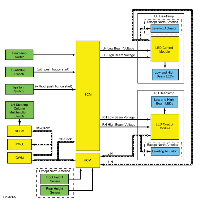
.jpg)
| Item | Description |
|---|---|
| 1 | HS-CAN2 |
| 2 | BCM |
| 3 | LH low beam voltage |
| 4 | LH high beam voltage |
| 5 | RH low beam voltage |
| 6 | RH high beam voltage |
| 7 | SCCM |
| 8 | Headlamp switch |
| 9 | LH steering column multifunction switch |
| 10 | IPMA |
| 11 | GWM |
| 12 | HS-CAN1 |
| 13 | Start/Stop switch |
| 14 | HCM |
| 15 | LIN |
| 16 | LIN |
| 17 | LH headlamp |
| 18 | LED control module |
| 19 | LED control module |
| 20 | Leveling actuator |
| 21 | Leveling actuator |
| 22 | Except North America |
| 23 | Except North America |
| 24 | Ignition switch |
| 25 | Low and high beam Light Emitting Diodes (LEDs) |
| 26 | RH headlamp |
| 27 | Low and high beam Light Emitting Diodes (LEDs) |
| 28 | (without push button start) |
| 29 | (with push button start) |
| 30 | Front height sensor |
| 31 | Rear height sensor |
| 32 | Except North America |
Network Message Chart
BCM Network Input Messages
| Broadcast Message | Originating Module | Message Purpose |
|---|---|---|
| Headlamp flash to pass status | GWM | Indicates to the BCM a request for the high beams or flash-to-pass. |
GWM Network Input Messages
| Broadcast Message | Originating Module | Message Purpose |
|---|---|---|
| Headlamp flash to pass status | SCCM | Indicates to the GWM a request for the high beams or flash-to-pass. |
| Auto high beam request | IPMA | Indicates to the GWM a request for the high beams based on the IPMA camera input. |
HCM Network Input Messages
| Broadcast Message | Originating Module | Message Purpose |
|---|---|---|
| Headlamp low status | BCM | Indicates to the HCM a request for the low beams. |
| High beam status | BCM | Indicates to the HCM a request for the high beams or flash-to-pass. |
Low Beams
The BCM monitors the headlamp switch position by sending voltage signals on multiple circuits to the headlamp switch. There is one circuit for each headlamp switch position. At any given time, one of the signal circuits is switched to ground to indicate the headlamp switch position.
The BCM turns the parking lamps and headlamps on when the ignition is in ON and the BCM detects a fault from the headlamp switch or wiring. This is normal behavior of the BCM when a fault has been detected with the inputs from the headlamp switch.
When the ignition is in ON, the BCM supplies voltage to the LED control module attached to each headlamp assembly through the low beam headlamp circuit. This LED control module is used to control the low beam Light Emitting Diodes (LEDs).
When the BCM receives a request to turn the headlamps on, it sends a low beam message over the HS-CAN1 to the HCM. The HCM sends the low beam message over the LIN circuit to the LED control module attached to each headlamp assembly to illuminate the low beam Light Emitting Diodes (LEDs).
During low beam operation, the low beam Light Emitting Diodes (LEDs) illuminate through the headlamp assembly projector lens.
The BCM also provides Field Effect Transistor (FET) protection of the low beam output circuits. When an excessive current draw is detected, the BCM disables the affected circuit driver.
High Beams
The SCCM monitors the LH steering column multifunction switch for a high beam request. When the LH steering column multifunction switch is in the HIGH BEAMS position, the SCCM sends a message over the HS-CAN2 to the GWM, then the GWM sends the message to the BCM over the HS-CAN1.
When the BCM receives a message requesting the high beams, it sends a high beam message over the HS-CAN1 to the HCM. The HCM sends the high beam message over the LIN circuit to the LED control module attached to each headlamp assembly to illuminate the high beam LED in addition to the low beam Light Emitting Diodes (LEDs). This changes the headlamp beam brightness to illuminate a greater distance.
When the ignition is in ON, the BCM supplies voltage to the LED control module attached to each headlamp assembly through the high beam headlamp circuit. This LED control module is used to control the high beam LED.
The BCM also provides Field Effect Transistor (FET) protection of the exterior lamps switched voltage and high beam output circuits. When an excessive current draw is detected, the BCM disables the affected circuit driver.
Automatic High Beams
The automatic high beam system uses an interior rear view mirror mounted camera to monitor surrounding traffic conditions and high beam usage. The camera is hardwired to the IPMA and serviced as an assembly. The IPMA communicates light information over the HS-CAN2 to the GWM then the GWM sends the information to the BCM over the HS-CAN1.
The automatic high beam feature is active only when the headlamp switch is in the AUTOLAMPS position.
During nighttime driving, the automatic high beam system automatically turns the high beams on if it is dark enough and no other traffic is present. When the system detects an approaching vehicle's headlamps or a preceding vehicle's rear lamps, the system turns off the high beams. When the approaching vehicle's headlamps or the preceding vehicle's rear lamps are no longer detected, the high beams automatically turn back on.
The IPMA turns the high beam headlamps on when the following conditions are met:
- The feature has been enabled using the message center
- The headlamp switch is in the AUTOLAMPS position and the autolamps feature has turned the exterior lamps on
- The vehicle speed is greater than 51 km/h (32 mph)
- The IPMA determines the ambient lighting conditions are dark enough
- The IPMA does not detect any light source that can be interpreted as an illuminated vehicle lamp
The IPMA turns the high beams off if any of the following occur:
- The IPMA detects any light source that can be interpreted as an illuminated vehicle lamp
- The IPMA determines the ambient lighting conditions are not dark enough
- The vehicle speed falls below 44 km/h (27 mph)
- The autolamps are turned off
- The IPMA determines the view is blocked
Flash-To-Pass
The SCCM monitors the LH steering column multifunction switch for a flash-to-pass request. When the LH steering column multifunction switch is in the FLASH-TO-PASS position, the SCCM sends a message over the HS-CAN2 to the GWM then the GWM sends the message to the BCM over the HS-CAN1.
When the ignition is in RUN and the flash-to-pass is requested, the high beams are activated as long as the LH steering column multifunction switch is held in the FLASH-TO-PASS position.
Headlamp Exit Delay
When the ignition is OFF and the multifunction switch is placed in the flash-to-pass position and released, the parking lamps and low beams are illuminated. They remain illuminated until:
- 3 minutes have elapsed with a door open.
- 30 seconds have elapsed after all doors are closed.
- the multifunction switch is placed in the flash-to-pass position again.
- the ignition switches to RUN.
Within the 30 second delay after all the doors are closed, opening any door results in the 3 minute timer restarting.
Signature Lighting
When the ignition is in ON, the BCM supplies voltage to the LED control module attached to each headlamp assembly. This module is used to control the signature/park lamps.
The signature/park lamps illuminate when the following is true:
- the headlamp switch is in the AUTOLAMPS position
- the ambient light sensor receives enough light that the headlamps are not commanded on
- the DRL are configured on
When the BCM receives a message requesting the parking lamps on, it sends a message over the LIN circuit to the LED control module attached to each headlamp assembly to reduce the intensity of the signature/park lamp Light Emitting Diodes (LEDs).
When the parking lamps are off, the signature/park lamp Light Emitting Diodes (LEDs) illuminate at full intensity.
When the BCM sends a RH or LH turn message through the LIN circuit to the LED control modules, the corresponding signature/park lamp is turned off while the turn signal is active. When the turn signal is no longer active, the daytime signature/park lamp once again illuminates.
Automatic Headlamp Leveling - Except North America
The headlamp beam height will be automatically adjusted according to vehicle load, speed, acceleration and braking data received from the ABS module, PCM and the vehicle height sensors.
The front lighting uses the HCM to command the up/down aiming of the headlamps through the LIN to the headlamp assemblies. The headlamp assemblies contain a module that receive the messages through the LIN from the HCM.
Depending on the inputs received (steering wheel angle and vehicle speed for example), the HCM can command the height at which the headlamps are aimed (up or down) to improve nighttime visibility. Automatic headlamp leveling is activated when the headlamp switch is in the HEADLAMPS or AUTOLAMPS position.
DRL
System Diagram
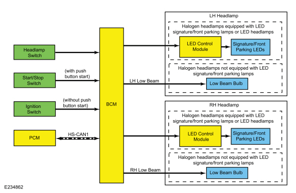
.jpg)
| Item | Description |
|---|---|
| 1 | RH low beam |
| 2 | low beam |
| 3 | BCM |
| 4 | Headlamp switch |
| 5 | HS-CAN1 |
| 6 | Start/Stop switch |
| 7 | PCM |
| 8 | Ignition switch |
| 9 | Signature/front parking Light Emitting Diodes (LEDs) |
| 10 | LED control module |
| 11 | LH headlamp |
| 12 | Halogen headlamps equipped with LED signature/front parking lamps or LED headlamps |
| 13 | Low beam bulb |
| 14 | Halogen headlamps not equipped with LED signature/front parking lamps |
| 15 | Signature/front parking Light Emitting Diodes (LEDs) |
| 16 | LED control module |
| 17 | RH headlamp |
| 18 | Halogen headlamps equipped with LED signature/front parking lamps or LED headlamps |
| 19 | Low beam bulb |
| 20 | Halogen headlamps not equipped with LED signature/front parking lamps |
| 21 | (without push button start) |
| 22 | (with push button start) |
Network Message Chart
BCM Network Input Messages
| Broadcast Message | Originating Module | Message Purpose |
|---|---|---|
| Gear lever position | PCM | Indicates the gear selector lever position to the BCM. When the selector lever is in any position other than park, the BCM activates the DRL. |
DRL
For halogen headlamps not equipped with LED signature/front parking lamps, the DRL system utilizes the existing circuitry and components from the headlamp low beam system.
For halogen headlamps equipped with LED signature/front parking lamps and LED headlamps, the DRL system operates the signature/park lamp Light Emitting Diodes (LEDs) at full intensity. The BCM supplies voltage to the LED control module. When the BCM supplies voltage through the DRL circuit to the LED control module, the LED control module illuminates the signature/park lamp Light Emitting Diodes (LEDs) at full intensity.
The BCM monitors the ignition status, the headlamp switch and autolamp status.
There are two types of DRL, conventional (where it is required) and configurable.
When equipped with conventional DRL, the DRL are active in any headlamp switch position except the HEADLAMPS position.
The conventional DRL are activated when the following conditions are met:
- the ignition is ON
- the headlamps switch is in OFF, PARKLAMPS or AUTOLAMPS position and the headlamps have not been turned on by the autolamp system.
- the transmission is not in PARK
When equipped with configurable DRL, the DRL may be enabled through the IPC message center. When enabled, the DRL are active only in the AUTOLAMPS headlamp position. When autolamps request the headlamps on, the DRL are de-activated.
The configurable DRL are activated when the following conditions are met:
- the ignition is ON.
- the headlamps switch is in AUTOLAMPS position and the headlamps have not been turned on by the autolamp system.
- the transmission is not in PARK.
When the transmission is in not in PARK, the PCM sends a message over the HS-CAN1 to the BCM indicating the transmission is not in PARK.
Autolamps
System Diagram
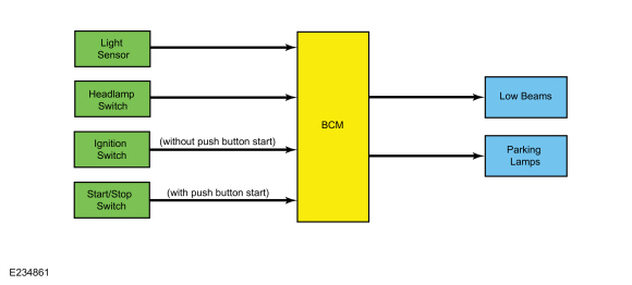
.jpg)
| Item | Description |
|---|---|
| 1 | BCM |
| 2 | Parking lamps |
| 3 | Ignition switch |
| 4 | Start/Stop switch |
| 5 | Headlamp switch |
| 6 | Light sensor |
| 7 | Low beams |
| 8 | (without push button start) |
| 9 | (with push button start) |
Autolamps
The BCM sends ground and a reference voltage to the light sensor with a voltage signal. The voltage drop on the reference voltage circuit varies with the ambient light conditions.
The BCM monitors the headlamp switch circuits to indicate the headlamp switch position.
When the BCM receives a headlamp switch status indicating a request for the autolamps, the BCM monitors the light sensor for the ambient light condition. If the BCM determines the ambient light level is dark, the BCM supplies voltage to the exterior lamps.
Headlamps On With Wipers On Function
When the headlamp switch is in the autolamps ON position, the exterior lamps turn on when the front wipers are on low or high speed. This feature does not activate the exterior lamps during a mist wipe, while the wipers are on to clear washer fluid during a wash condition or the wipers are in automatic mode.
The exterior lamps turn off when the ignition changes to OFF or ACC mode, the headlamp switch is placed in the off position, or the front wipers are turned OFF. The exception to this is when the exterior lights are on because of darkness determined by the autolamp system.
Stoplamps
System Diagram
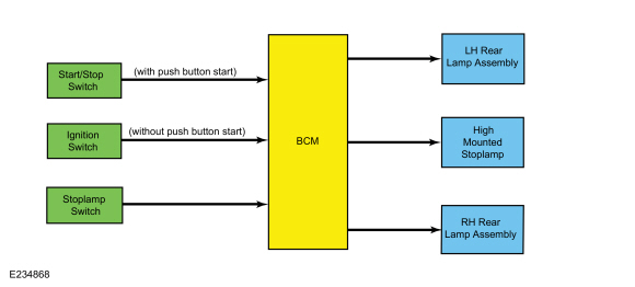
.jpg)
| Item | Description |
|---|---|
| 1 | BCM |
| 2 | LH rear lamp assembly |
| 3 | RH rear lamp assembly |
| 4 | Stoplamp switch |
| 5 | High mounted stoplamp |
| 6 | Start/Stop switch |
| 7 | Ignition switch |
| 8 | (without push button start) |
| 9 | (with push button start) |
Stoplamps
The BCM monitors the input from the stoplamp switch. When the brake pedal is applied, voltage is routed to the BCM. The BCM then supplies voltage to the stoplamps.
The BCM also provides an overload protection of the stoplamp output circuits. When an excessive current draw is detected, the BCM disables the affected stoplamp circuit driver.
Turn Signal and Hazard Lamps
System Diagram
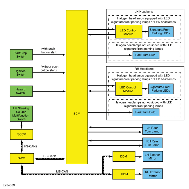
.jpg)
| Item | Description |
|---|---|
| 1 | HS-CAN2 |
| 2 | SCCM |
| 3 | GWM |
| 4 | HS-CAN1 |
| 5 | Start/Stop switch |
| 6 | Hazard switch |
| 7 | BCM |
| 8 | LH exterior mirror |
| 9 | RH exterior mirror |
| 10 | DDM |
| 11 | PDM |
| 12 | LH steering column multifunction switch |
| 13 | MS-CAN |
| 14 | RH rear turn lamp |
| 15 | LH rear turn lamp |
| 16 | Ignition switch |
| 17 | Signature/front parking Light Emitting Diodes (LEDs) |
| 18 | LED control module |
| 19 | LH Headlamp |
| 20 | Halogen headlamps equipped with LED signature/front parking lamps or LED headlamps |
| 21 | Park/turn bulb |
| 22 | Halogen headlamps not equipped with LED signature/front parking lamps |
| 23 | Signature/front parking Light Emitting Diodes (LEDs) |
| 24 | LED control module |
| 25 | RH Headlamp |
| 26 | Halogen headlamps equipped with LED signature/front parking lamps or LED headlamps |
| 27 | Park/turn bulb |
| 28 | Halogen headlamps not equipped with LED signature/front parking lamps |
| 29 | (without push button start) |
| 30 | (with push button start) |
Network Message Chart
BCM Network Input Messages
| Broadcast Message | Originating Module | Message Purpose |
|---|---|---|
| Turn signal switch status | GWM | Indicates the turn signal stalk position on the multifunction switch (left/right lane change or turn signal on or off). The BCM activates the left/right turn signals based on this input. |
GWM Network Input Messages
| Broadcast Message | Originating Module | Message Purpose |
|---|---|---|
| Turn signal switch status | SCCM | Indicates the turn signal stalk position on the multifunction switch (left/right lane change or turn signal on or off). |
DDM and PDM Network Input Messages
| Broadcast Message | Originating Module | Message Purpose |
|---|---|---|
| Left turn lamp request | BCM | A command to the DDM or PDM to activate/deactivate the exterior mirror turn indicator. |
| Right turn lamp request | BCM | A command to the DDM or PDM to activate/deactivate the exterior mirror turn indicator. |
Turn Signals - Halogen Headlamps
The SCCM monitors the LH steering column multifunction switch position. When the LH steering column multifunction switch is in the LH TURN or RH TURN position, the SCCM sends a message over the HS-CAN2 to the GWM then the GWM sends the message to the BCM over the HS-CAN1 indicating a request for the LH or RH turn signal.
When the BCM receives a request for a turn signal, the BCM supplies on/off voltage to the appropriate turn lamps. The BCM sends a turn indicator command message over the Medium-Speed Controller Area Network (MS-CAN) to the door modules for the exterior mirror turn lamps.
The timed on/off cycle for turn lamps is determined by the BCM and is set to flash approximately 70 times per minute if both the front and rear turn signal lamps operate correctly.
The rear turn lamps are Light Emitting Diodes (LEDs) in the rear lamp assemblies and have an outage circuit that tells the BCM when the Light Emitting Diodes (LEDs) are inoperative. During normal operation, when voltage is applied to the rear turn Light Emitting Diodes (LEDs), the feedback circuit sends the same voltage back to the BCM through the outage circuit. If the Light Emitting Diodes (LEDs) are inoperative the BCM will not receive this voltage feedback through the outage circuit.
If a front or rear turn signal lamp is inoperative, the BCM fast flashes the remaining turn lamp(s) approximately 150 times per minute to indicate a bulb outage to the driver.
The LH steering column multifunction has 2 detents for the left turn position and 2 detents for the right turn position. When placed in the first detent and released, the corresponding turn signals flash 3 times and turn off. When the LH steering column multifunction switch is moved to the second detent, the turn signal flashes until the steering wheel is turned in the opposite direction.
The BCM also provides Field Effect Transistor (FET) protection of the turn lamp output circuits. When an excessive current draw is detected, the BCM disables the affected turn lamp circuit driver.
Turn Signals - LED Headlamps
The SCCM monitors the LH steering column multifunction switch position. When the LH steering column multifunction switch is in the LH TURN or RH TURN position, the SCCM sends a message over the HS-CAN2 to the GWM then the GWM sends the message to the BCM over the HS-CAN1 indicating a request for the LH or RH turn signal.
The BCM sends a turn indicator command message over the HS-CAN1 to the GWM then the MS-CAN to the door modules for the exterior mirror turn lamps (if equipped).
The timed on/off cycle for turn lamps is determined by the BCM and is set to flash approximately 70 times per minute if both the front and rear turn signal lamps operate correctly.
The BCM supplies voltage to the LED control module. When the BCM receives a request for a turn signal, the BCM supplies on/off voltage through the front turn signal circuit to the LED control module, the LED control module illuminates the turn lamp Light Emitting Diodes (LEDs). The turn lamps are Light Emitting Diodes (LEDs) and have an outage circuit that tells the BCM when the Light Emitting Diodes (LEDs) are inoperative. During normal operation, when voltage is applied to the turn Light Emitting Diodes (LEDs), the feedback circuit sends the same voltage back to the BCM through the outage circuit. If the Light Emitting Diodes (LEDs) are inoperative the BCM will not receive this voltage feedback through the outage circuit.
For the rear turn lamps, when the BCM receives a request for a turn signal, the BCM supplies on/off voltage to the appropriate rear turn lamp Light Emitting Diodes (LEDs). The turn lamps are Light Emitting Diodes (LEDs) and have an outage circuit that tells the BCM when the Light Emitting Diodes (LEDs) are inoperative. During normal operation, when voltage is applied to the turn Light Emitting Diodes (LEDs), the feedback circuit sends the same voltage back to the BCM through the outage circuit. If the Light Emitting Diodes (LEDs) are inoperative the BCM will not receive this voltage feedback through the outage circuit.
If a front or rear turn signal lamp is inoperative, the BCM fast flashes the remaining turn lamp(s) approximately 150 times per minute to indicate a LED outage to the driver.
The LH steering column multifunction switch has 2 detents for the left turn position and 2 detents for the right turn position. When placed in the first detent and released, the corresponding turn signals flash 3 times and turn off. When the LH steering column multifunction switch is moved to the second detent, the turn signal flashes until the steering wheel is turned in the opposite direction.
The BCM also provides Field Effect Transistor (FET) protection of the turn lamp output circuits. When an excessive current draw is detected, the BCM disables the affected turn lamp circuit driver.
Hazard Lamps
The BCM sends a voltage signal to the hazard flasher lamp switch to monitor for a hazard lamp function request. When the hazard flasher lamp switch is pressed, the voltage signal is routed to ground, indicating a request to activate or deactivate the hazard lamp function.
When the BCM receives a request for the hazard lamps, the BCM supplies on/off voltage to all the turn lamps.
The timed on/off cycle for the hazard lamps is approximately 70 times per minute, regardless of bulb outage.
Parking, Rear, and License Plate Lamps
System Diagram
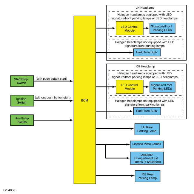
.jpg)
| Item | Description |
|---|---|
| 1 | BCM |
| 2 | Headlamp switch |
| 3 | RH Rear Parking Lamp |
| 4 | LH Rear Parking Lamp |
| 5 | License plate lamps |
| 6 | Start/Stop switch |
| 7 | Signature/front parking Light Emitting Diodes (LEDs) |
| 8 | LED control module |
| 9 | LH headlamp |
| 10 | Ignition switch |
| 11 | Halogen headlamps equipped with LEDsignature/front parking lamps or LED headlamps |
| 12 | Park/turn bulb |
| 13 | Halogen headlamps not equipped with LED signature/front parking lamps |
| 14 | Signature/front parking Light Emitting Diodes (LEDs) |
| 15 | LED control module |
| 16 | RH headlamp |
| 17 | Halogen headlamps equipped with LEDsignature/front parking lamps or LED headlamps |
| 18 | Park/turn bulb |
| 19 | Halogen headlamps not equipped with LED signature/front parking lamps |
| 20 | Luggage compartment lid lamps (if equipped) |
| 21 | (without push button start) |
| 22 | (with push button start) |
Parking Lamps
The BCM monitors the headlamp switch position by sending voltage signals on multiple circuits to the headlamp switch. There is one circuit for each headlamp switch position. At any given time, one of the signal circuits is switched to ground to indicate the headlamp switch position.
If the BCM detects a fault from the headlamp switch or loses communication with the headlamp switch, the BCM turns the parking and headlamps on. This is normal behavior of the BCM when a fault has been detected with the inputs from the headlamp switch.
For front parking lamps on vehicles with halogen headlamps not equipped with LED signature/front parking lamps, when the BCM receives an input requesting the parking lamps on, it provides voltage to the front parking lamps.
For front parking lamps on vehicles with halogen headlamps equipped with LED signature/front parking lamps and LED headlamps, the BCM supplies voltage to the LED control module. When the BCM receives a request for parking lamps, the BCM supplies voltage through the parking lamps circuit to the LED control module, the LED control module illuminates the LED signature/front parking lamps at a reduced intensity.
For rear parking lamps, when the BCM receives an input requesting the parking lamps on, it provides voltage to the front parking lamps.
The BCM also provides Field Effect Transistor (FET) protection of the parking lamps output circuits. When an excessive current draw is detected, the BCM disables the affected parking lamps circuit driver.
Fog Lamps
System Diagram
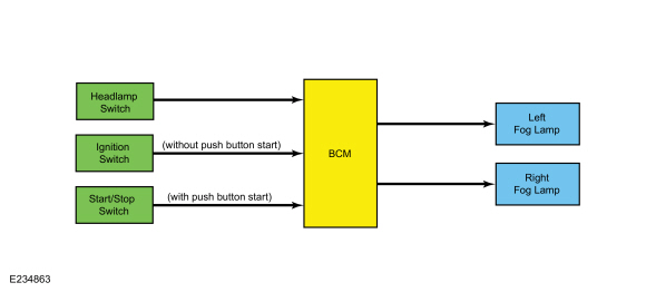
.jpg)
| Item | Description |
|---|---|
| 1 | BCM |
| 2 | RH fog lamp |
| 3 | Ignition switch |
| 4 | Start/Stop switch |
| 5 | Headlamp switch |
| 6 | LH fog lamp |
| 7 | (without push button start) |
| 8 | (with push button start) |
Fog Lamps
The BCM monitors the headlamp switch position by sending voltage signals on multiple circuits to the headlamp switch. There is one circuit for each headlamp switch position. At any given time, one of the signal circuits is switched to ground to indicate the headlamp switch position.
When the BCM receives input from the headlamp switch indicating a request for the fog lamps, the BCM provides voltage to the fog lamps.
The BCM also provides an overload protection of the fog lamp output circuits. When an excessive current draw is detected, the BCM disables the affected fog lamp circuit driver.
Reversing Lamps
System Diagram
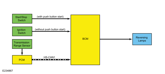
.jpg)
| Item | Description |
|---|---|
| 1 | HS-CAN1 |
| 2 | Transmission range sensor |
| 3 | PCM |
| 4 | BCM |
| 5 | Reversing lamps |
| 6 | Start/Stop switch |
| 7 | Ignition switch |
| 8 | (without push button start) |
| 9 | (with push button start) |
Network Message Chart
BCM Network Input Messages
| Broadcast Message | Originating Module | Message Purpose |
|---|---|---|
| Gear lever position | PCM | Indicates the transmission is in reverse gear to the BCM. When the transmission is in REVERSE and the ignition in RUN, the BCM provides voltage to the reversing lamps. |
Reversing Lamps
When the transmission is in REVERSE, the PCM sends a message over the HS-CAN1 to the BCM indicating the transmission is in REVERSE. The BCM provides voltage to the reversing lamp when it receives the message that the transmission is in REVERSE and the ignition is in RUN.
The BCM also provides Field Effect Transistor (FET) protection of the reversing lamp output circuit. When an excessive current draw is detected, the BCM disables the affected reversing lamps circuit driver.
Field Effect Transistor (FET) Protection
A Field Effect Transistor (FET) is a type of transistor that, when used with module software, monitors and controls current flow on module outputs. The Field Effect Transistor (FET) protection strategy prevents module damage in the event of excessive current flow.
The BCM utilizes a Field Effect Transistor (FET) protective circuit strategy for many of its outputs (for example, a headlamp output circuit). Output loads (current level) are monitored for excessive current (typically short circuits) and are shut down (turns off the voltage or ground provided by the module) when a fault event is detected. A short circuit DTC is stored at the fault event and a cumulative counter is started.
When the demand for the output is no longer present, the module resets the Field Effect Transistor (FET) circuit protection to allow the circuit to function. The next time the driver requests a circuit to activate that has been shut down by a previous short (Field Effect Transistor (FET) protection) and the circuit is still shorted, the Field Effect Transistor (FET) protection shuts off the circuit again and the cumulative counter advances.
When the excessive circuit load occurs often enough, the module shuts down the output until a repair procedure is carried out. Each Field Effect Transistor (FET) protected circuit has 3 predefined levels of short circuit tolerance based on the harmful effect of each circuit fault on the Field Effect Transistor (FET) and the ability of the Field Effect Transistor (FET) to withstand it. A module lifetime level of fault events is established based upon the durability of the Field Effect Transistor (FET). If the total tolerance level is determined to be 600 fault events, the 3 predefined levels would be 200, 400 and 600 fault events.
When each tolerance level is reached, DTC U1000:00 sets along with the short circuit DTC that was stored on the first failure. These Diagnostic Trouble Codes (DTCs) cannot be cleared until the vehicle is repaired.
After the repair, it is necessary to clear the Diagnostic Trouble Codes (DTCs). Use the clear DTC operation on the scan tool, cycle the ignition, and run the BCM on-demand self-test.
The module never resets the fault event counter to zero and continues to advance the fault event counter as short circuit fault events occur. If the number of short circuit fault events reach the third level, DTC U3000:49 sets along with the associated short circuit DTC. DTC U3000:49 cannot be cleared and the module must be replaced after the initial fault is repaired.
Component Description
Headlamp Assembly
Exterior lamps are vented to accommodate normal changes in pressure. Condensation can be a natural by-product of this design. When moist air enters the lamp assembly through the vents, condensation can occur if the temperature is cold. When normal condensation occurs, a thin mist forms on the interior of the lens. The thin mist eventually clears and exits through the vents during normal operation. The amount of time it takes to clear the lens of acceptable mist varies with ambient humidity and lamp types. Normal condensation clears from any lamp in 48 hours under dry conditions.
Do not replace a lamp assembly with acceptable levels of condensation such as the presence of thin mist (no streaks, drip marks or droplets are present) or a fine mist covers less than 50% of the lens.
Examples of unacceptable moisture (usually caused by a lamp housing leak) are water puddling inside the lamp or large water droplets, drip marks or streaks present on the interior of the lens.
Headlamp Switch
The BCM monitors the headlamp switch position by sending voltage signals on multiple circuits to the headlamp switch. There is one circuit for each headlamp switch position. At any given time, one of the signal circuits is switched to ground to indicate the headlamp switch position.
Light Sensor
The BCM sends a voltage signal to the light sensor. The light sensor provides resistance between the voltage signal and ground. The resistance varies depending on the amount of ambient light detected by the light sensor. The brighter the ambient light, the lower the resistance. By varying the resistance, the BCM can determine the amount of ambient light.
Stoplamp Switch
The stoplamp switch is a normally open switch and is provided voltage at all times. When the brake pedal is applied, the switch closes and routes voltage to the BCM.
 Exterior Lighting - Overview. Description and Operation
Headlamps
The headlamp system consists of:
Headlamp assemblies
Headlamp switch
Adaptive front lighting module (halogen headlamps equipped with LED signature/front parking lamps and LED headlamps)
LH steering column multifunction switch
BCM
HCM
SCCM
IPMA
For
halogen headlamps, the headlamp system is a quad-beam pattern system...
 Autolamps. Diagnosis and Testing
DTC Chart: BCM
Diagnostics in this manual assume a certain skill level and knowledge of Ford-specific diagnostic practices. REFER to: Diagnostic Methods (100-00 General Information, Description and Operation)...
Other information:
Ford Fusion 2013–2020 Service Manual: Catalyst Monitor Sensor. Removal and Installation
Special Tool(s) / General Equipment 303-476 (T94P-9472-A) Socket, Exhaust Gas Oxygen SensorTKIT-1994-LM/MTKIT-1994-FTKIT-1994-FLM/FM Materials Name Specification Motorcraft® High Temperature Nickel Anti-Seize LubricantXL-2 - Motorcraft® Penetrating and Lock LubricantXL-1 - Removal Disconnect the catalyst monitor sensor electrical co..
Ford Fusion 2013–2020 Owners Manual: Using MyKey With Remote Start Systems. MyKey – Troubleshooting
Using MyKey With Remote Start Systems MyKey is not compatible with non Ford-approved, aftermarket remote start systems. If you choose to install a remote start system, see an authorized dealer for a Ford-approved remote start system. MyKey – Troubleshooting ..
Categories
- Manuals Home
- 2nd Generation Ford Fusion Owners Manual
- 2nd Generation Ford Fusion Service Manual
- Automatic Transmission - 6-Speed Automatic Transmission – 6F35
- Transmission - 1.5L EcoBoost (118kW/160PS) – I4. Removal and Installation
- Cylinder Head. Removal and Installation
- New on site
- Most important about car
Using Seatbelts During Pregnancy
WARNING: Always ride and drive with your seatback upright and properly fasten your seatbelt. Fit the lap portion of the seatbelt snugly and low across the hips. Position the shoulder portion of the seatbelt across your chest. Pregnant women must follow this practice. See the following figure.
