Ford Fusion: Exterior Lighting / Autolamps. Diagnosis and Testing
DTC Chart: BCM
Diagnostics in this manual assume a certain skill level and knowledge of Ford-specific diagnostic practices.
REFER to: Diagnostic Methods (100-00 General Information, Description and Operation).
BCM DTC Chart
| DTC | Description | Action |
|---|---|---|
| B1A85:11 | Ambient Light Sensor: Circuit Short To Ground | GO to Pinpoint Test B |
| B1A85:13 | Ambient Light Sensor: Circuit Open | GO to Pinpoint Test B |
Symptom Chart(s)
Diagnostics in this manual assume a certain skill level and knowledge of Ford-specific diagnostic practices.
REFER to: Diagnostic Methods (100-00 General Information, Description and Operation).
Symptom Chart: Autolamps
Symptom Chart
| Condition | Possible Sources | Actions |
|---|---|---|
| A module does not respond to the scan tool |
|
REFER to: Communications Network (418-00 Module Communications Network, Diagnosis and Testing). |
| The autolamps are inoperative | Refer to the Pinpoint Test | GO to Pinpoint Test A |
| The autolamps are on continuously | Refer to the Pinpoint Test | GO to Pinpoint Test B |
Pinpoint Tests
The Autolamps Are Inoperative
Refer to Wiring Diagrams Cell 85 for schematic and connector information.
Normal Operation and Fault Conditions
REFER to: Exterior Lighting - Overview (417-01 Exterior Lighting, Description and Operation).
REFER to: Exterior Lighting - System Operation and Component Description (417-01 Exterior Lighting, Description and Operation).
Possible Sources
- Light sensor
- BCM
PINPOINT TEST A : THE AUTOLAMPS ARE INOPERATIVE
| A1 CHECK THE MANUAL HEADLAMP OPERATION | ||||||||||||||||
Do the headlamps operate correctly?
|
||||||||||||||||
| A2 CHECK FOR VOLTAGE TO THE LIGHT SENSOR | ||||||||||||||||
Is the voltage approximately 5 volts?
|
||||||||||||||||
| A3 CHECK FOR CORRECT BCM (BODY CONTROL MODULE) OPERATION | ||||||||||||||||
Is the concern still present?
|
The Autolamps Are On Continuously
Refer to Wiring Diagrams Cell 85 for schematic and connector information.
Normal Operation and Fault Conditions
REFER to: Exterior Lighting - Overview (417-01 Exterior Lighting, Description and Operation).
REFER to: Exterior Lighting - System Operation and Component Description (417-01 Exterior Lighting, Description and Operation).
DTC Fault Trigger Conditions
| DTC | Description | Fault Trigger Conditions |
|---|---|---|
| B1A85:11 | Ambient Light Sensor: Circuit Short To Ground | A continuous memory and on-demand DTC that sets when the BCM detects a short to ground from the light sensor input circuit. |
| B1A85:13 | Ambient Light Sensor: Circuit Open | An on-demand DTC that sets when the BCM detects an open or short to voltage from the light sensor input circuit. |
Possible Sources
- Wiring, terminals or connectors
- Light sensor
- BCM
Visual Inspection and Diagnostic Pre-checks
- Inspect the headlamp switch for damage.
- Inspect the light sensor for damage.
PINPOINT TEST B : THE AUTOLAMPS ARE ON CONTINUOUSLY
| B1 CHECK FOR BCM (BODY CONTROL MODULE) DIAGNOSTIC TROUBLE CODE (DTCS) | ||||||||||||||||||||||
Is DTC B1A85:11 or B1A85:13 present?
|
||||||||||||||||||||||
| B2 CHECK FOR VOLTAGE TO THE LIGHT SENSOR (NO DTC (DIAGNOSTIC TROUBLE CODE) ) | ||||||||||||||||||||||
Is the voltage approximately 5 volts?
|
||||||||||||||||||||||
| B3 CHECK FOR VOLTAGE TO THE LIGHT SENSOR (DTC (DIAGNOSTIC TROUBLE CODE) B1A85:11) | ||||||||||||||||||||||
Is the voltage approximately 5 volts?
|
||||||||||||||||||||||
| B4 CHECK THE LIGHT SENSOR INPUT CIRCUIT FOR A SHORT TO GROUND | ||||||||||||||||||||||
Is the resistance greater than 10,000 ohms?
|
||||||||||||||||||||||
| B5 CHECK FOR VOLTAGE TO THE LIGHT SENSOR (DTC (DIAGNOSTIC TROUBLE CODE) B1A85:13) | ||||||||||||||||||||||
Is the voltage approximately 5 volts?
|
||||||||||||||||||||||
| B6 CHECK THE LIGHT SENSOR GROUND | ||||||||||||||||||||||
Is the voltage approximately 5 volts?
|
||||||||||||||||||||||
| B7 CHECK THE LIGHT SENSOR GROUND CIRCUIT FOR AN OPEN | ||||||||||||||||||||||
Is the resistance less than 3 ohms?
|
||||||||||||||||||||||
| B8 CHECK THE LIGHT SENSOR INPUT CIRCUIT FOR A SHORT TO VOLTAGE | ||||||||||||||||||||||
Is any voltage present?
|
||||||||||||||||||||||
| B9 CHECK THE LIGHT SENSOR INPUT CIRCUIT FOR AN OPEN | ||||||||||||||||||||||
Is the resistance less than 3 ohms?
|
||||||||||||||||||||||
| B10 CHECK FOR CORRECT BCM (BODY CONTROL MODULE) OPERATION | ||||||||||||||||||||||
Is the concern still present?
|
 Fog Lamps. Diagnosis and Testing
DTC Chart: BCM
Diagnostics in this manual assume a certain skill level and knowledge of Ford-specific diagnostic practices. REFER to: Diagnostic Methods (100-00 General Information, Description and Operation)...
Other information:
Ford Fusion 2013–2020 Service Manual: Cylinder Head. Disassembly and Assembly of Subassemblies
Special Tool(s) / General Equipment 303-1249Valve Spring CompressorTKIT-2006UF-FLMTKIT-2006UF-ROW 303-300 (T87C-6565-A) Set, Valve Spring CompressorTKIT-1988-FESTIVAT88C-1000-STTKIT-1988-TRACERTKIT-2009TC-F 303-350 (T89P-6565-A) Compressor, Valve SpringTKIT-1990-LMHTKIT-1989-FTKIT-1989-FMTKIT-1989-FLM 303-472 (T94P-6565-AH) Adapter, Valve Spring CompressorTKIT-199..
Ford Fusion 2013–2020 Service Manual: Lane Keeping System - System Operation and Component Description. Description and Operation
System Operation Lane Keeping Alert and Lane Keeping Aid Item Description 1 IPMA 2 LH steering column multifunction switch 3 Lane keeping system switch 4 GWM 5 RCM 6 SCCM 7 PCM 8 IPC 9 BCM 10 PSCM 11 CCM 12 with adaptive cruise control 13 ABS m..
Categories
- Manuals Home
- 2nd Generation Ford Fusion Owners Manual
- 2nd Generation Ford Fusion Service Manual
- Garage Door Opener
- Powertrain
- Electrical
- New on site
- Most important about car
Fuel Quality
Choosing the Right Fuel

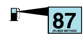
Your vehicle is designed to operate on regular unleaded gasoline with a minimum pump (R+M)/2 octane rating of 87.


 Click here to access Guided Routine (BCM).
 Internet Explorer version 11 or greater is required to perform this Pinpoint Test.


 Click here to access Guided Routine (BCM).
 Internet Explorer version 11 or greater is required to perform this Pinpoint Test.