Ford Fusion: Evaporative Emissions - 1.5L EcoBoost (118kW/160PS) – I4 / Evaporative Emissions - System Operation and Component Description. Description and Operation
Ford Fusion 2013–2020 Service Manual / Powertrain / Engine / Evaporative Emissions - 1.5L EcoBoost (118kW/160PS) – I4 / Evaporative Emissions - System Operation and Component Description. Description and Operation
System Operation
Refer to the PC/ED manual section 1 Description and Operation.
System Diagram
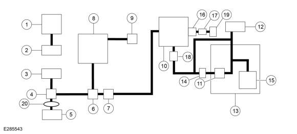
| Item | Description |
|---|---|
| 1 | Valve cover |
| 2 | Turbocharger inlet pipe |
| 3 | Air cleaner (ACL) outlet pipe |
| 4 | Vapor ejector |
| 5 | Turbocharger to CAC (Charge Air Cooler) tube |
| 6 | Dual check valve |
| 7 | EVAP (Evaporative Emission) canister purge valve |
| 8 | Intake manifold |
| 9 | PCV (Positive Crankcase Ventilation) valve |
| 10 | EVAP canister |
| 11 | Fuel vapor vent valve (internal to tank) |
| 12 | Fuel tank filler pipe |
| 13 | Fuel tank |
| 14 | Fuel tank pressure (FTP) sensor and tube |
| 15 | Fuel level sensor (internal to tank) |
| 16 | EVAP canister inlet filter |
| 17 | EVAP canister vent solenoid |
| 18 | EVAP blocking valve |
| 19 | Spider trap |
| 20 | Single check valve |
 Evaporative Emissions - Overview. Description and Operation
Overview
The EVAP
system prevents hydrocarbon emissions from entering the atmosphere by
storing fuel vapors and routing the vapors to the engine to be consumed
during normal engine operation...
 Evaporative Emissions. Diagnosis and Testing
Engine Diagnostic Information
Diagnostics
in this manual assume a certain skill level and knowledge of
Ford-specific diagnostic practices. For information about these,REFER to: Diagnostic Methods (100-00 General Information, Description and Operation)...
Other information:
Ford Fusion 2013–2020 Service Manual: Selector Lever Cable Bushing. Removal and Installation
Removal Turn the ignition switch to the OFF position and apply the parking brake. Remove the air cleaner assembly. Refer to: Air Cleaner (303-12D Intake Air Distribution and Filtering - 2.7L EcoBoost (238kW/324PS), Removal and Installation)...
Ford Fusion 2013–2020 Service Manual: Evaporative Emission Canister Purge Valve. Removal and Installation
Removal NOTE: Removal steps in this procedure may contain installation details. Remove the engine appearance cover. Remove the air cleaner outlet pipe. Refer to: Air Cleaner Outlet Pipe (303-12A Intake Air Distribution and Filtering - 1...
Categories
- Manuals Home
- 2nd Generation Ford Fusion Owners Manual
- 2nd Generation Ford Fusion Service Manual
- Cylinder Head. Removal and Installation
- Body Control Module (BCM). Removal and Installation
- Load Carrying
- New on site
- Most important about car
Adjusting the Steering Wheel
WARNING: Do not adjust the steering wheel when your vehicle is moving.
Note: Make sure that you are sitting in the correct position.
Copyright © 2026 www.fofusion2.com