Ford Fusion: Supplemental Restraint System / Driver Knee Airbag. Removal and Installation
Removal
NOTE: Removal steps in this procedure may contain installation details.
-
If a SRS fault is present, continue to Step 2. Otherwise, turn the ignition off, wait at least one minute and continue to Step 3. WARNING:
Turn the ignition OFF and wait one minute to deplete
the backup power supply. Ignition must remain OFF until repair is
complete. Failure to follow this instruction may result in serious
personal injury or death in the event of an accidental deployment.
-
Depower the SRS.
Refer to: Supplemental Restraint System (SRS) Depowering and Repowering (501-20B Supplemental Restraint System, General Procedures).
-
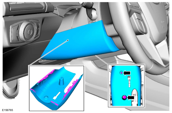
Remove the screws, release the outer clips on each side and remove the lower steering column shroud.
 |
-
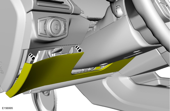
Detatch the instrument panel lower trim panel.
 |
-
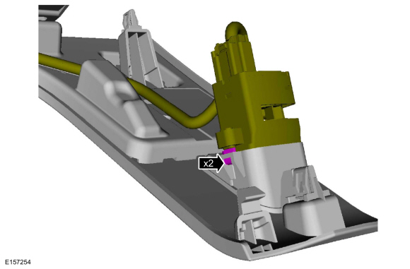
Detatch the tabs and disconnect the in-vehicle temperature and humidity sensor.
 |
-
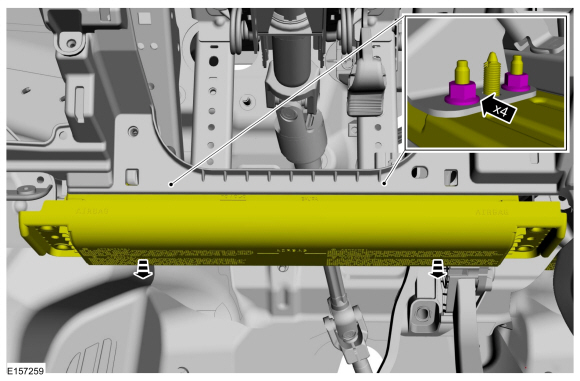
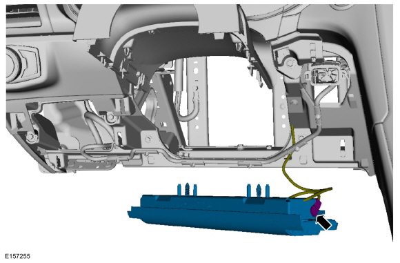
Remove the nuts and drop the driver knee airbag down.
Torque: 97 lb.in (11 Nm)
 |
-
Disconnect the electrical connector and remove the driver knee airbag.
 |
Installation
-
To install, reverse the removal procedure.
-
If the SRS was depowered, repower the SRS.
Refer to: Supplemental Restraint System (SRS) Depowering and Repowering (501-20B Supplemental Restraint System, General Procedures).
 Driver Airbag. Removal and Installation
Removal
WARNING:
Turn the ignition OFF and wait one minute to deplete
the backup power supply. Ignition must remain OFF until repair is
complete...
 Front Door Side Impact Sensor. Removal and Installation
Removal
NOTE:
Removal steps in this procedure may contain installation details.
WARNING:
Turn the ignition OFF and wait one minute to deplete
the backup power supply...
Other information:
Ford Fusion 2013–2020 Service Manual: Airbag Supplemental Restraint System (SRS). Diagnosis and Testing
DTC Chart: Restraint Control Module (RCM) Diagnostics in this manual assume a certain skill level and knowledge of Ford-specific diagnostic practices. REFER to: Diagnostic Methods (100-00 General Information, Description and Operation). RCM DTC Chart DTC Description Action B0001:11 Driver Frontal Stage 1 Deployment ..
Ford Fusion 2013–2020 Service Manual: Evaporative Emissions - System Operation and Component Description. Description and Operation
System Operation Refer to the PC/ED manual section 1 Description and Operation. System Diagram Item Description 1 Valve cover 2 Turbocharger inlet pipe 3 Air cleaner (ACL) outlet pipe 4 Vapor ejector 5 Turbocharger to CAC (Charge Air Cooler) tube 6 Dual check valve 7 EVAP (Evaporative Emission) canister pur..
Categories
- Manuals Home
- 2nd Generation Ford Fusion Owners Manual
- 2nd Generation Ford Fusion Service Manual
- Transmission - 1.5L EcoBoost (118kW/160PS) – I4. Removal and Installation
- Engine
- Pre-Collision Assist (IF EQUIPPED)
- New on site
- Most important about car
Understanding Your Tire Pressure Monitoring System
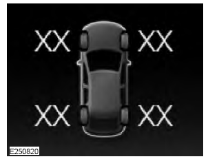
The tire pressure monitoring system measures pressure in your road tires and sends the tire pressure readings to your vehicle. You can view the tire pressure readings through the information display. The low tire pressure warning light will turn on if the tire pressure is significantly low. Once the light is illuminated, your tires are under-inflated and need to be inflated to the manufacturer’s recommended tire pressure. Even if the light turns on and a short time later turns off, your tire pressure still needs to be checked.
