Ford Fusion: Supplemental Restraint System / Driver Airbag. Removal and Installation
Ford Fusion 2013–2020 Service Manual / Body and Paint / Body and Paint / Supplemental Restraint System / Driver Airbag. Removal and Installation
Removal
-
If a SRS fault is present, continue to Step 2. Otherwise, turn the ignition off, wait at least one minute and continue to Step 3. WARNING:
Turn the ignition OFF and wait one minute to deplete
the backup power supply. Ignition must remain OFF until repair is
complete. Failure to follow this instruction may result in serious
personal injury or death in the event of an accidental deployment.
WARNING:
Turn the ignition OFF and wait one minute to deplete
the backup power supply. Ignition must remain OFF until repair is
complete. Failure to follow this instruction may result in serious
personal injury or death in the event of an accidental deployment.
-
Depower the SRS.
Refer to: Supplemental Restraint System (SRS) Depowering and Repowering (501-20B Supplemental Restraint System, General Procedures).
-
-
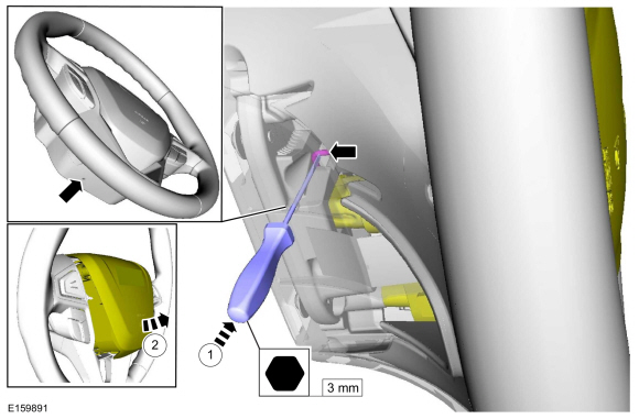
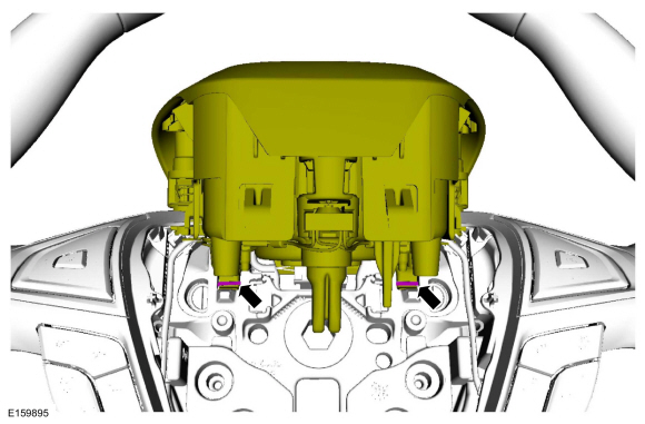
At the bottom of the steering wheel, locate the
hole, insert a 3 mm (0.125 inch) Allen key and push in on the steering
wheel spring clip to release the driver airbag retainer.
-
Pull the driver airbag out and separate it from the steering wheel.
-
At the bottom of the steering wheel, locate the
hole, insert a 3 mm (0.125 inch) Allen key and push in on the steering
wheel spring clip to release the driver airbag retainer.
Click here to view a video version of this procedure.

 |
-
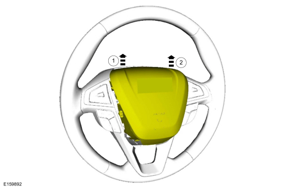
- Pull up firmly on the LH side of the driver airbag and disengage it from the spring clip.
- Pull up firmly on the RH side of the driver airbag and disengage it from the spring clip.
 |
-
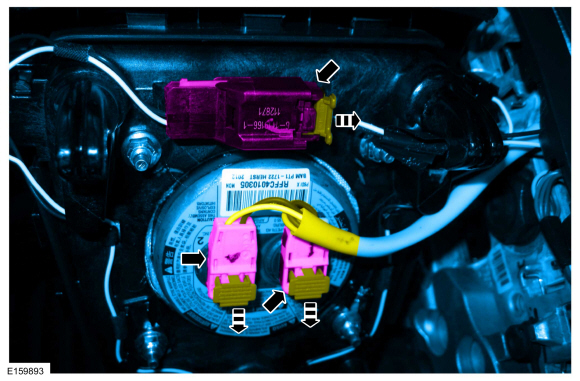
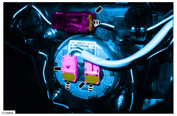
Disconnect the electrical connectors.
 |
Installation
-
Connect the electrical connectors.
 |
-
Engage the 2 driver airbag retaining hooks to the steering wheel spring clips.
 |
-
-
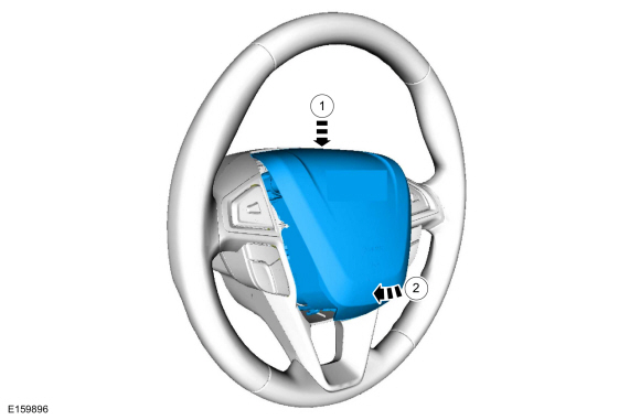
Push down on the driver airbag.
-
Pivot the driver airbag down and engage the lower retaining hook to the spring clip.
-
Push down on the driver airbag.
 |
-
If the SRS was depowered, repower the SRS.
Refer to: Supplemental Restraint System (SRS) Depowering and Repowering (501-20B Supplemental Restraint System, General Procedures).
 Clockspring. Removal and Installation
Removal
NOTE:
Removal steps in this procedure may contain installation details.
WARNING:
Turn the ignition OFF and wait one minute to deplete
the backup power supply...
 Driver Knee Airbag. Removal and Installation
Removal
NOTE:
Removal steps in this procedure may contain installation details.
WARNING:
Turn the ignition OFF and wait one minute to deplete
the backup power supply...
Other information:
Ford Fusion 2013–2020 Owners Manual: Changing a Road Wheel Procedure
WARNING: When one of the front wheels is off the ground, the transmission alone will not prevent the vehicle from moving or slipping off the jack, even if the transmission is in park (P). WARNING: To help prevent your vehicle from moving when changing a wheel, shift the transmission into park (P), set the parking brake and use an appropriate block or wheel chock to secure the wheel diago..
Ford Fusion 2013–2020 Service Manual: Active Grille Shutter. Removal and Installation
Removal NOTE: Removal steps in this procedure may contain installation details. Remove the front bumper cover. Refer to: Front Bumper Cover (501-19 Bumpers, Disassembly and Assembly). On both sides. Remove the pin-type retainers. Remove the bolts. Torque: 53 lb.in (6 Nm) Remove the bolts. ..
Categories
- Manuals Home
- 2nd Generation Ford Fusion Owners Manual
- 2nd Generation Ford Fusion Service Manual
- Automatic Transmission Fluid Check - 1.5L EcoBoost™/2.0L EcoBoost™/2.5L. Automatic Transmission Fluid Check - 2.7L EcoBoost™
- Starter Motor. Removal and Installation
- Intake Manifold. Removal and Installation
- New on site
- Most important about car
Direction Indicators. Interior Lamps
Direction Indicators

Push the lever up or down to use the direction indicators.
Copyright © 2026 www.fofusion2.com