Ford Fusion: Supplemental Restraint System / Clockspring. Removal and Installation
Removal
NOTE: Removal steps in this procedure may contain installation details.
-
If a SRS fault is present, continue to Step 2. Otherwise, turn the ignition OFF, wait at least one minute and continue to Step 3. WARNING:
Turn the ignition OFF and wait one minute to deplete
the backup power supply. Ignition must remain OFF until repair is
complete. Failure to follow this instruction may result in serious
personal injury or death in the event of an accidental deployment.
WARNING:
Turn the ignition OFF and wait one minute to deplete
the backup power supply. Ignition must remain OFF until repair is
complete. Failure to follow this instruction may result in serious
personal injury or death in the event of an accidental deployment.
-
Depower the SRS.
Refer to: Supplemental Restraint System (SRS) Depowering and Repowering (501-20B Supplemental Restraint System, General Procedures).
-
NOTE: To install, remove the anti-rotation key from a new clockspring after installing the steering wheel.
Remove the steering wheel.
Refer to: Steering Wheel (211-04 Steering Column, Removal and Installation).
 |
-
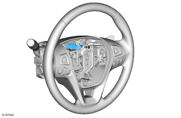
Remove the steering column shrouds.
Refer to: Steering Column Shrouds (501-05 Interior Trim and Ornamentation, Removal and Installation).
-
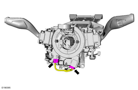
Disconnect the clockspring electrical connectors.
 |
-
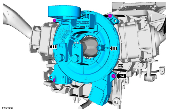
Remove the screws and the clockspring.
 |
Installation
-
NOTICE: If installing a new clockspring, do not remove the clockspring anti-rotation key until the steering wheel is installed. If the anti-rotation key has been removed before installing the steering wheel, the clockspring must be centered. Failure to follow this instruction may result in component damage and/or system failure.
To install, reverse the removal procedure.
-
NOTE: This step is only necessary if adjustment or centralizing is required.
Adjust the clockspring.
Refer to: Clockspring Adjustment (501-20B Supplemental Restraint System, General Procedures).
-
If the SRS was depowered, repower the SRS.
Refer to: Supplemental Restraint System (SRS) Depowering and Repowering (501-20B Supplemental Restraint System, General Procedures).
 C-Pillar Side Impact Sensor. Removal and Installation
Removal
NOTE:
Removal steps in this procedure may contain installation details.
WARNING:
Turn the ignition OFF and wait one minute to deplete
the backup power supply...
 Driver Airbag. Removal and Installation
Removal
WARNING:
Turn the ignition OFF and wait one minute to deplete
the backup power supply. Ignition must remain OFF until repair is
complete...
Other information:
Ford Fusion 2013–2020 Service Manual: Direct Current/Direct Current (DC/DC) Converter Control Module. Diagnosis and Testing
Diagnostics in this manual assume a certain skill level and knowledge of Ford-specific diagnostic practices. REFER to: Diagnostic Methods (100-00 General Information, Description and Operation). DTC Chart: Direct Current/Direct Current (DC/DC) Converter Control Module DTC Description Action B1310:11 Run/Start Control: Circuit Short To..
Ford Fusion 2013–2020 Service Manual: Charge Air Cooler Coolant Temperature (CACCT) Sensor. Removal and Installation
Materials Name Specification Motorcraft® Orange Prediluted Antifreeze/CoolantVC-3DIL-B WSS-M97B44-D2 Removal NOTE: Removal steps in this procedure may contain installation details. Refer to: Jacking and Lifting - Overview (100-02 Jacking and Lifting, Description and Operation). NOTE: When releasing the cooling system pressure, cover the coolant..
Categories
- Manuals Home
- 2nd Generation Ford Fusion Owners Manual
- 2nd Generation Ford Fusion Service Manual
- Electronic Parking Brake (EPB) Service Mode Activation and Deactivation. General Procedures
- Engine
- Transmission - 1.5L EcoBoost (118kW/160PS) – I4. Removal and Installation
- New on site
- Most important about car
Manual Climate Control

Note: Depending on your vehicle option package, the controls may look different from what you see here.