Ford Fusion: Engine - 1.5L EcoBoost (118kW/160PS) – I4 / Valve Cover. Removal and Installation
Special Tool(s) /
General Equipment
| Hose Clamp Remover/Installer |
Materials
| Name |
Specification |
Flange Sealant
CU7Z-19B508-A |
WSS-M2G348-A11
|
Motorcraft® Metal Surface Prep Wipes
ZC-31-B |
-
|
Engine Oil - SAE 5W-20 - Synthetic Blend Motor Oil
XO-5W20-Q1SP |
WSS-M2C945-B1
|
Removal
-
Release the fuel system pressure.
Refer to: Fuel System Pressure Release (310-00A Fuel System - General Information - 1.5L EcoBoost (118kW/160PS) – I4, General Procedures).
-
Remove the engine appearance cover.
-
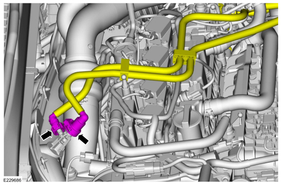
Disconnect the EVAP canister purge valve tubes from the TC inlet pipe.
-
-
Remove the oil level indicator.
-
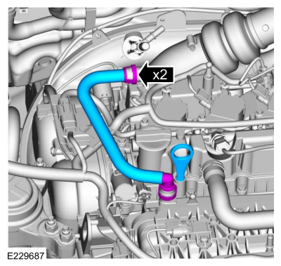
Disconnect the couplings and remove the hose.
-
-
Detach the wiring harness retainer from the hose.
-
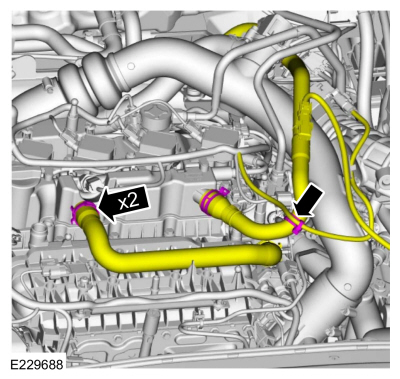
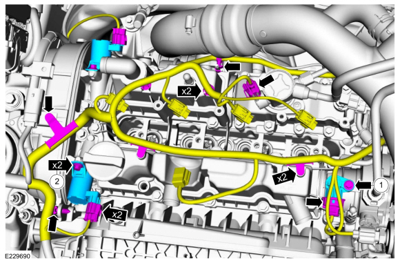
Release the clamps and position the hoses aside.
Use the General Equipment: Hose Clamp Remover/Installer
-
Remove the fuel rail.
Refer to: Fuel Rail (303-04A Fuel Charging and Controls - 1.5L EcoBoost (118kW/160PS) – I4, Removal and Installation).
-
NOTE:
Note the position of the VCT oil control solenoids before removal.
-
Detach the wiring harness retainers and disconnect the wiring harness electrical connectors.
-
Remove the bolts and the VCT oil control solenoids.
-
Remove the bolt and the intake CMP sensor.
-
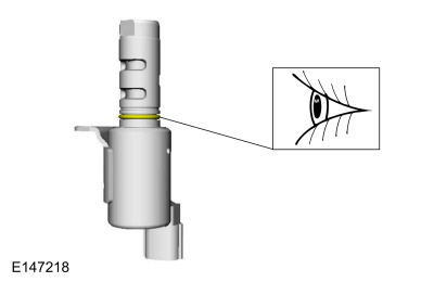
NOTE:
The O-ring seals are to be reused unless damaged.
Inspect the VCT oil control solenoid O-ring seal.
-
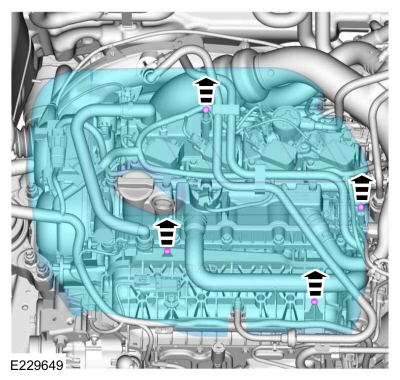
NOTE:
Do not set the valve cover sealing surface face down
on a bench as the check valve and splitter leg is susceptible to
breakage.
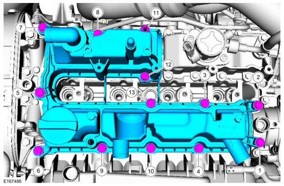
Remove the bolts in sequence shown and the valve cover.
-
Remove and discard the valve cover gasket.
Installation
-
NOTICE:
Do not use metal scrapers, wire brushes, power
abrasive discs or other abrasive means to clean the sealing surfaces.
These tools cause scratches and gouges which make leak paths.
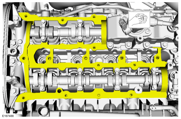
Make sure that the mating faces are clean and free of foreign material.
Material: Motorcraft® Metal Surface Prep Wipes
/ ZC-31-B
-
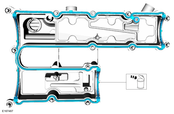
Install the new valve cover gasket.
-
NOTE:
The components must be installed within 5 minutes of applying the sealant.
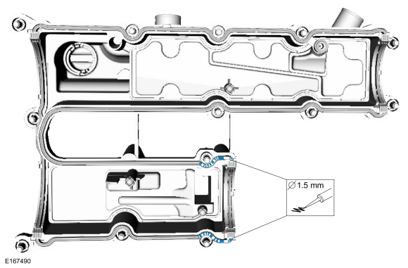
Apply a 1.5 mm (0.059 in) beads of gasket maker as shown.
Material: Flange Sealant
/ CU7Z-19B508-A
(WSS-M2G348-A11)
-
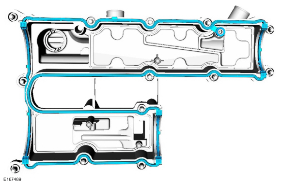
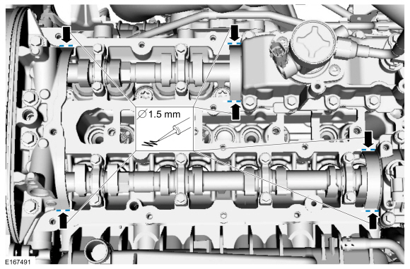
Apply a 1.5 mm (0.059 in) beads of gasket maker as shown.
Material: Flange Sealant
/ CU7Z-19B508-A
(WSS-M2G348-A11)
-
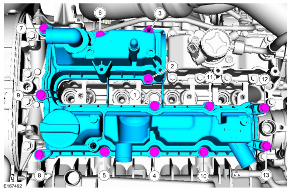
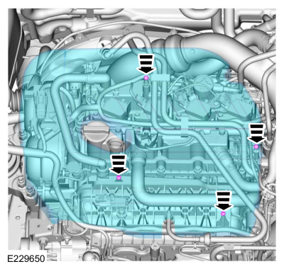
Install the valve cover and the bolts in sequence shown in 3 stages.
Torque:
Stage 1:
44 lb.in (5 Nm)
Stage 2:
80 lb.in (9 Nm)
Stage 3:
89 lb.in (10 Nm)
-
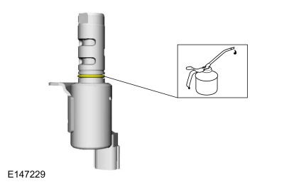
NOTE:
The O-ring seals are to be reused unless damaged.
Lubricate the VCT oil control solenoid O-ring seal.
Material: Engine Oil - SAE 5W-20 - Synthetic Blend Motor Oil
/ XO-5W20-Q1SP
(WSS-M2C945-B1)
-
NOTE:
Note the position of the VCT oil control solenoids before removal.
-
Install the intake CMP sensor and the bolt.
Torque:
80 lb.in (9 Nm)
-
Install the VCT oil control solenoids and the bolts.
Torque:
71 lb.in (8 Nm)
-
Attach the wiring harness retainers and connect the wiring harness electrical connectors.
-
Install the fuel rail.
Refer to: Fuel Rail (303-04A Fuel Charging and Controls - 1.5L EcoBoost (118kW/160PS) – I4, Removal and Installation).
-
-
Position the hoses and release the clamps.
Use the General Equipment: Hose Clamp Remover/Installer
-
Attach the wiring harness retainer to the hose.
-
-
Install the hose and connect the couplings.
-
Install the oil level indicator.
-
Connect the EVAP canister purge valve tubes to the TC inlet pipe.
-
Install the engine appearance cover.
Special Tool(s) /
General Equipment
303-1097Locking Tool, Variable Camshaft Timing Oil Control UnitTKIT-2010B-FLMTKIT-2010B-ROW
303-1552Alignment Tool, CamshaftTKIT-2012A-FLTKIT-2012A-ROW
Hot Air Gun
Hose Clamp Remover/Installer
Materials
Name
Specification
Flange SealantCU7Z-19B508-A
WSS-M2G348-A11
Motorcraft® Metal Surface Prep WipesZC-31-B
-&..
Other information:
Special Tool(s) /
General Equipment
Scraper for Straight Edges
Hot Air Gun
8 mm Drill Bit
MIG/MAG Welding Equipment
Spot Weld Drill Bit
Locking Pliers
Materials
Name
Specification
Seam SealerTA-2-B, 3M™ 08308, LORD Fusor® 803DTM
-
Removal
NOTICE:
Battery electric vehicle (BEV), hybrid electric vehicle
(HEV) and plug-in hybrid electr..
This device complies with Part 15 of the
FCC Rules and with Industry Canada
license-exempt RSS standard(s).
Operation is subject to the following two
conditions: (1) This device may not cause
harmful interference, and (2) This device
must accept any interference received,
including interference that may cause
undesired operation.
WARNING: Changes or
modifications not expressively approved..


 Variable Camshaft Timing (VCT) Unit. Removal and Installation