Ford Fusion: Lane Keeping System / Lane Keeping System - System Operation and Component Description. Description and Operation
System Operation
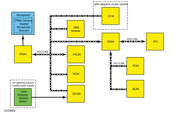
Lane Keeping Alert and Lane Keeping Aid
.jpg)
| Item | Description |
|---|---|
| 1 | IPMA |
| 2 | LH steering column multifunction switch |
| 3 | Lane keeping system switch |
| 4 | GWM |
| 5 | RCM |
| 6 | SCCM |
| 7 | PCM |
| 8 | IPC |
| 9 | BCM |
| 10 | PSCM |
| 11 | CCM |
| 12 | with adaptive cruise control |
| 13 | ABS module |
| 14 | Windshield |
| 15 | IPMA camera heated windshield element |
Lane Keeping System Operation
The lane keeping system is turned on and off using the lane keeping system switch on the LH steering column multifunction switch. The last known on/off setting for the lane keeping system is recalled every time the ignition is turned on. When a MyKey® is in use, the system defaults the lane keeping alert mode to on but the driver can activate/deactivate the system, change the mode and select all lane keeping alert intensity settings. When the system is on, it is active only when the vehicle speed is above 64 km/h (40 mph) and at least one lane marking can be detected by the camera. The system can be turned off at any time by pressing the lane keeping system switch.
The system can be temporarily suppressed at any time by the following:
- Rapid braking or acceleration
- Evasive steering maneuver
- Using the turn signal indicator
Lane Keeping Alert
The lane keeping alert generates vibration through the steering wheel when an unintended lane departure is detected by the IPMA. When commanded by the IPMA, the PSCM rapidly oscillates the power steering left to right, simulating the vehicle driving on a rumble strip. The intensity of the steering wheel vibration can be adjusted using the Driver Assist options in the message center. The system also provides a visual alert in the message center when a lane departure is detected.
Lane Keeping Aid
The lane keeping aid provides steering torque to help the driver keep the vehicle in the lane when an unintended lane departure is detected. The IPMA sends the road curvature and calculated steering angle messages to the PSCM. The PSCM uses these messages to calculate and generate the intervention torque.
Hands-Off Warning
When the lane keeping aid is active, the PSCM continuously monitors the torque sensor in the EPAS system to determine if a hand is on the steering wheel and sends the data to the IPMA. If the IPMA detects that the driver's hands are off the wheel for more than a few seconds, the hands-off warning is generated.
The hands-off warning is generated in 2 levels. The first level is a message center warning only and is triggered after 3 seconds of hands-off driving is detected. The second level warning consists of a message center warning and an audio chime and is generated after 6 seconds of hands-off driving.
NOTE: Due to certain road conditions and the driver's individual grip/touch on the steering wheel, the system may generate a hands-off warning when hand(s) are still on the steering wheel.
IPMA Camera Heated Windshield Element
The IPMA camera heated windshield element keeps the windshield in front of the IPMA clear of condensation, frost and ice. The IPMA uses input from the IPMA camera and the ambient air temperature to turn the IPMA camera heated windshield element on and off as needed. Voltage and ground is supplied to the heated windshield element by the IPMA. After start-up, the IPMA camera heated windshield element may be commanded on if the ambient temperature is below 5°C (41°F).
System Display
When the lane keeping system is turned on, an overhead graphic of a vehicle and lane markings is displayed in the LH IPC display. If the lane keeping aid mode is selected when the system is on, arrow markings pointing toward the lane lines are also displayed. When the system is off, the lane marking graphics are not displayed. The overhead vehicle graphic may still be displayed if adaptive cruise control is enabled. While the system is on, the color of the lane markings change to indicate the system status.
Gray: Indicates the system is temporarily unable to provide a lane keeping aid or alert activation on the indicated side(s). This may be caused by:
- The vehicle speed is under the activation limit
- High sunload on the IPMA camera lens
- Too close to lane markings
- Lane markings are too narrow or wide
- Road has no or poor lane markings in the camera field-of-view
- Following a vehicle in front too closely
- IPMA camera blocked
- Windshield dirty or damaged
- Standing water on the road
- Environmental conditions (significant sun angles, shadows, snow, heavy rain or fog)
- Turn signal is active
- Vehicle is in a dynamic maneuver
- Tight curves on the road
Green: Indicates the system is available or ready to provide a lane keeping aid or alert activation on the indicated side(s).
Yellow: Indicates the system is providing or has just provided a lane keeping aid activation.
Red: Indicates the system is providing or has just provided a lane keeping alert activation.
Message Center Settings
The system has 2 optional setting menus available through the Driver Assist menu in the message center. The last-known selection for each setting is stored by the IPMA and does not need to be set again after the key is cycled.
The Mode setting allows the driver to select which of the system features is enabled and turned on when the button is pressed. The 3 options in this menu are:
- Lane Keeping Alert only - provides a steering wheel vibration when an unintended lane departure is detected.
- Lane Keeping Aid only - provides steering input toward the center of the lane when an unintended lane departure is detected.
- Lane Keeping Alert and Lane Keeping Aid - provides both a warning and steering input towards the center of the lane.
The Intensity setting allows the driver to select the intensity of the steering wheel vibration used in lane keeping alert mode. This setting does not impact the lane keeping aid mode. The 3 options in this menu are:
- Low
- Normal
- High
Camera Alignment
Camera alignment is required for the lane keeping alert and lane keeping aid to function correctly. The procedure is initiated using the diagnostic scan tool and requires about 10 minutes of driving above 64 km/h (40 mph) on a flat, straight road with highly visible lane markings to complete. If the alignment is unsuccessful, check the interior mirror for proper installation. The IPMA camera alignment procedure should be performed when any of the following occur:
- Windshield replacement
- Change in tire size
- Suspension repair, alignment or modifications
- Front air bag deployment
- Interior mirror replacement
NOTE: The alignment completion is indicated on the diagnostic scan tool. If the alignment is unsuccessful, check the interior mirror for proper installation.
NOTE: The FRONT CAMERA MALFUNCTION - SERVICE REQUIRED message in the IPC disappears when the system is aligned.
Component Description
IPMA
The IPMA is integral to the interior rear view mirror. The IPMA contains a forward-looking camera that is used to detect the position of the vehicle within the lane.
On vehicles equipped with adaptive cruise control and the collision warning system, the IPMA shares information with the CCM on dedicated CAN circuits to assist the driver in avoiding a collision. For additional information on the pre-collision assist system,
Refer to: Collision Warning and Collision Avoidance System - System Operation and Component Description (419-03B Collision Warning and Collision Avoidance System, Description and Operation).
On vehicles equipped with automatic high beams, the IPMA
camera is used to monitor surrounding traffic conditions and high beam
usage. For additional information on the automatic high beams feature,
Refer to: Exterior Lighting - System Operation and Component Description (417-01 Exterior Lighting, Description and Operation).
The IPMA requires PMI and camera alignment when replaced.
Refer to: Module Configuration - System Operation and Component Description (418-01 Module Configuration, Description and Operation).
IPMA Camera Heated Windshield Element
The IPMA camera heated windshield element is a resistive-type heater grid that is integrated into the windshield and located directly in front of the IPMA camera. The IPMA camera heated windshield element cannot be replaced separately from the windshield.
Before replacing the windshield or the IPMA for an IPMA camera heated windshield element concern, verify the integrity of the wiring, connectors and terminals.
Lane Keeping System Switch
The lane keeping system switch is a momentary contact switch located on the LH steering column multifunction switch. The lane keeping system switch inputs directly to the SCCM, which provides a switch state message to the IPMA.
 Lane Keeping System - Overview. Description and Operation
Overview
The
Lane Keeping System (LKS) has 2 functions, lane keeping aid and lane
keeping alert. The Lane Keeping System (LKS) utilizes the camera located
in the IPMA to detect
and track the road lane markings...
 Lane Keeping System. Diagnosis and Testing
DTC Chart(s)
Diagnostics in this manual assume a certain skill level and knowledge of Ford-specific diagnostic practices. REFER to: Diagnostic Methods (100-00 General Information, Description and Operation)...
Other information:
Ford Fusion 2013–2020 Owners Manual: Changing the 12V Battery
WARNING: Batteries normally produce explosive gases which can cause personal injury. Therefore, do not allow flames, sparks or lighted substances to come near the battery. When working near the battery, always shield your face and protect your eyes...
Ford Fusion 2013–2020 Service Manual: Horn. Diagnosis and Testing
DTC Chart Diagnostics in this manual assume a certain skill level and knowledge of Ford-specific diagnostic practices. REFER to: Diagnostic Methods (100-00 General Information, Description and Operation). BCM DTC Chart DTC Description Actions B1323:11 Horn Switch: Circuit Short To Ground GO to Pinpoint..
Categories
- Manuals Home
- 2nd Generation Ford Fusion Owners Manual
- 2nd Generation Ford Fusion Service Manual
- Main Control Valve Body. Removal and Installation
- Load Carrying
- Transmission - 1.5L EcoBoost (118kW/160PS) – I4. Removal and Installation
- New on site
- Most important about car
Parallel Parking
The system detects available parallel parking spaces and steers your vehicle into the space. You control the accelerator, gearshift and brakes. The system visually and audibly guides you into a parallel parking space.
 Press the button once to search
for a parking space.
Press the button once to search
for a parking space.